
Abstract
In the current scenario, micro-manufacturing through the electro-discharge machining (EDM) process is a prominent technique for achieving desired complex micro/nano-features of any product. The precision and accuracy of producing features are the prerequisites of micro-machining. The current work aims to check the feasibility of the novel Maglev EDM for fabricating micro-holes on a thin nickel sheet (thickness = 500 μm). The study presents the viability of the newly developed system by comparing it with the conventional EDM process. A pure direct current power supply is assembled with a magnetic levitation-based gap monitoring mechanism to overcome the setbacks of conventional EDM. The novel setup utilizes the combined effect of the permanent electromagnet to diminish arcing and short-circuiting. The control parameters for the operation were 12 V open-circuit voltage and 2 A peak current while maintaining a duty factor of 95.564 percent. The measured discharge voltage and discharge current were 6.64 V and 900 mA, respectively. Tungsten rod (ø 650 μm) and deionized water were used as a tool and a dielectric medium, respectively, for the experiment. Further, the machined micro-hole and micro-tool analysis have been carried out using high-resolution microscopy, scanning electron microscopy and energy dispersive spectroscopy reports. The newly developed Maglev EDM’s feasibility to produce micro-holes on conductive materials has been confirmed in the present work with an average material removal rate of 40 μg/min.
Introduction
Miniaturization of regularly used products and fabrication of compact portable devices have led to the increase in the development of micro-machining techniques in the present times. Micro-machining of modern-day advanced materials has led to several non-conventional machining processes. 1 Most conventional processes require a harder tool, direct contact and application of cutting force; such setbacks have been eradicated through the advanced machining processes. These processes easily achieve the fabrication of features and products with complex shapes and better accuracy. Electro-discharge machining (EDM) is an advanced machining process in which electro-conductive materials can be machined. Using this process, extremely hard and delicate materials can be easily machined with higher accuracy than conventional techniques. It is an electro-thermal process in which sparks are generated between the electrodes, which lead to the generation of extremely high-temperature plasma, while the electrodes are immersed in a dielectric fluid. 2 The electrodes act as the workpiece and tool, while the dielectric acts as an insulator until a particular voltage is applied, leading to its breakdown and discharge current flow due to conductive plasma. 3 The whole process takes place when the electrodes are kept at a specific distance (spark gap) from each other within the dielectric medium. The gap between the electrodes is maintained through a servo-controlled mechanism. The material removal occurs from both the electrodes through melting and vaporization. Due to its non-contact nature, the process exerts no mechanical stress and vibrations during machining.
During the EDM operation, the generation of sparks and the transaction of heat energy occur within a narrow gap (microns to submicron domain) between the interacting faces of the electrodes. The gap-controlling mechanism is essential for carrying out the machining operation. In general, a servo-controlled gap monitoring system is used to maintain the suitable machining gap in the EDM setup. The servo control system works reasonably well in avoiding arcing and short-circuiting phenomena during machining. Normally, the servo mechanism is designed using a lead screw and gear-based systems, which imposes mass inertia, backlash and wind-up losses. 4 These issues create a delay in the system’s response frequency, leading to the short-circuiting and arcing condition. These phenomena cause low process efficiency, stability and accuracy of machined products. Additionally, the transmission and response time delay of the servo controller also leads to the decrease in machining efficiency. Several developments have been made to improve the efficiency of the EDM process. Kumar et al. 5 discussed many possibilities to improve the EDM process in different domains. They also compared the process on the macro- and micro-domains. Micro-EDM is different than macro-EDM in terms of the size of the electrode, shorter pulses and higher resolution of finishing. The pulse generator in micro-EDM produces pulses in terms of micro- to nanoseconds. Very less amount of material is eroded due to the low amount of energy produced with each pulse, thus helping in fabricating micro-features.
Several types of research have been focused on further investigating the micro-EDM to improve the machining rate and increase machining efficiency. Several other types of research specify modifications such as air-assisted EDM, magnetic force-assisted EDM and vibration-assisted EDM. Many attempts have been made to gain a better material removal rate (MRR) using the EDM process, focusing on various key factors. The optimized results achieved by considering different process parameters show improvement in MRR on machining various materials. The achieved MRR also varies depending on the dielectric material used. The modifications made to the dielectric medium affect the MRR due to changes in the crater orientation caused by debris accumulation, layers of carbide, oxide, hydride formed, heat-affected area and many more. 6 Table 1 presents the applied modifications and hybridizations to the EDM technology to achieve specific improvements during the machining operation.
Advancement in EDM technology and its characteristics.

The development of micro-features using the EDM process has been the topic of research for the last 40 years. Masuzawa 18 presented an overview of the achieved micro-features using different manufacturing methods. Many limitations on micro-manufacturing were presented with an outline to better the EDM process. On moving towards the micro-domain of machining, problems such as handling of micro-features, the accuracy of positioning, control over the process and repeatability of the operation act as the setbacks. Kibria et al. 19 investigated the best possible outcomes achieved on utilizing different dielectrics. They studied the effect of both normal and powder-mixed dielectric conditions to compare the performance measures. Initially, relaxation type (RC-type) pulse generators were used in EDM, producing pulses of lower duration and high current using capacitor discharges. Later, field-effect transistors were used in the pulse generators to achieve high discharge frequency. Higher discharge frequency resulted in a better machining rate than the relaxation type circuits. The major drawback to the transistor type circuit is the transmission delay time and switch-off delay of the power transistor. The delay times add up to several nanoseconds, which restricts the system from producing short-duration pulses. 20 Though the RC-type circuit effectively produces short-duration pulses, the charging time delay of capacitor produces inconsistent discharge energy during machining. Several research studies have shown that an increase in pulse time improves MRR up to a certain extent. Further, an increase in pulse duration leads to reduced MRR due to decreased plasma strength. Moderate discharge time and proper gap control between the electrodes are essential to achieve effective and stable discharge during machining.
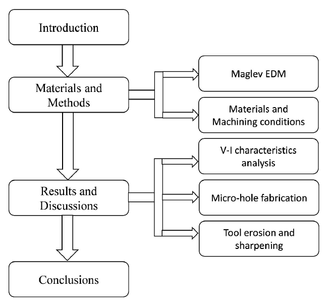
The current system works on the principle of magnetic levitation-based servo control, that is, Maglev. The designed novel servo system helps control the electrode gap during EDM operation while overcoming the previously specified issues. The discharge frequency of the Maglev system is higher than that of the conventional EDM. Also, the quick response phenomenon assists in overcoming the time delay and provides a stable discharge. The present work tested the feasibility of fabricating micro-holes using a magnetic controlled servo system based EDM, that is, Maglev EDM. The machining gap is maintained by applying two repulsive forces of arranged magnets and attaining the equilibrium condition. The shape and size of the fabricated micro-hole and post-processed micro-tool have been analysed using high-resolution microscopic images. The surface morphology and characteristics have been analysed using the scanning electron microscopy (SEM) micrographs. The elemental composition of the recast layer and the tool interacting surface has been observed through energy dispersive spectroscopy (EDS) reports. Further, studying the voltage–current (V–I) characteristics of Maglev EDM and comparing it with conventional EDM show the stability and effective nature of the system for fabricating the micro-hole. Figure 1 illustrates the flow of work in the current study.
Flow of work.
Materials and methods
In the current research, a novel EDM system is utilized to conduct the experimentation. The novel setup uses a pure DC power source in place of a complex power supply arrangement. The tool positioning unit is controlled by the combined effect of repulsive and restoring forces of magnets instead of the commonly used servo control system.
Maglev EDM
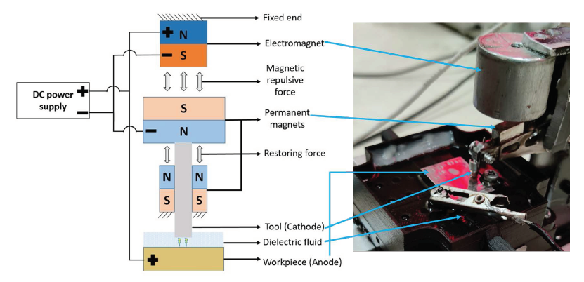
The present system implements a combination of an electromagnet and permanent magnets to control the tool movement and maintain a proper discharge gap between the electrodes. The system works on the principle of balance between dual magnetic repulsive forces. It consists of one electromagnet and two permanent magnets. The tool holder is attached to a permanent magnet which lies between the top electromagnet and the bottom permanent magnet. The repulsive force acting between the electromagnet and the tool holder magnet helps move the tool towards the workpiece. On the other hand, the repulsive force between the two permanent magnets acts as the restoring force. A DC power supply is connected to the electrodes and parallelly with the electromagnet. The arrangement was made in such a way that the movement of the tool electrode towards the workpiece decreases the interelectrode gap. The reduction in the interelectrode gap decreases the voltage potential of the electromagnet and hence reduces the magnetic field strength of the electromagnet. As magnetic repulsive force decreases, the restoring force magnitude starts increasing. A situation comes where the electromagnetic repulsive force will be equal to the restoring force. In this situation, the discharge occurs and materials are removed. The occurrence of discharge reduces the magnetic field strength of the electromagnet, and the tool will be retracted back to the initial gap condition. The cycle repeats continuously, and machining occurs through the electrical discharge. 17 Figure 2 illustrates the schematic view of the Maglev EDM mechanism.
Maglev EDM mechanism.
In comparison with the previous conventional EDM setup, the servo mechanism used was mainly a lead screw-based (or) gear-based complex system. The current system uses a simple magnetic repulsive force for tool positioning. Conventional EDM uses an RC-based (or) transistor-based power supply, while the Maglev EDM uses a pure DC power supply. In an RC-circuit, the charging of the capacitor takes time, and then it is used for the discharge; and in the case of a transistor-based circuit, it uses logic gate control which is complex. 5 Moreover, in Maglev EDM, the tool retraction occurs with quick response due to magnetic action, reducing the arcing and short-circuiting phenomena.
Materials and machining conditions
A thin nickel sheet (thickness = 500 μm) has been selected for the present machining operation as the workpiece material. Nickel has high corrosion resistance against air and water, making it suitable for use as a corrosive resistant coating. Moreover, it is used to prepare different types of superalloys such as Nimonic, Inconel, Rene and Monel, for applications in jet engines, powerplants and turbine parts. The micro-tool used is a tungsten rod of diameter 650 μm. Deionized water was used as a dielectric medium for the present research. A DC power source is connected to both the electrodes, where the micro-tool is connected to the cathode (−ve) polarity and the workpiece is connected to the anode (+ve) polarity. The control parameters for the operation were 12 V open-circuit voltage and 2 A peak current while maintaining a duty factor of 95.564%. Table 2 presents the materials used and the machining conditions chosen for the current investigation.
Materials and machining conditions.
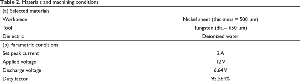
A digital oscilloscope (Make: Tektronix) was used to analyse the discharge waveforms with the actual discharge voltage and current during the machining operation. A high-definition microscope (Make: Olympus-BX51M) was used to observe and analyse the machined micro-hole as well as the interacting tool face. Furthermore, SEM was used to observe the surface topography and morphology of the machined micro-hole and tool tip. The EDS reports help in determining the elemental composition of workpiece and tool electrodes. Table 2 presents the materials used and the machining conditions chosen for the current investigation. Figure 3 shows the SEM micrograph of the micro-tool used for the operation along with its EDS report.
Tungsten micro-tool. (a) SEM micrograph of non-machined tool tip and (b) EDS report of tool material.
The cylindrical non-machined tool tip is observed through the SEM microscope, as illustrated in Figure 2(a). The surface is adequately even to make proper contact with the workpiece surface for efficient machining. The EDS report of the tool material shows 84.04% of tungsten content as the major constituent element. Figure 2(b) presents a detailed plot of the elements in the tool along with the percentage content chart of each element.
Results and discussions
Analysis of V–I characteristics of EDM and Maglev EDM
Segregation of the generated voltage and current pulse waves has been a major aspect of determining (or) monitoring the discharge gap in EDM for many decades. Studying the pulse waves is needful to generate an idea of the happenings in the narrow IEG and control the process parameters according to the desired actions. The current and voltage waveform during machining were captured using a differential type of current (Hantek, 65A, AC/DC) and a voltage probe (TPP0201, Tektronix) in digital storage oscilloscope (Tektronix, TDS2012C, 2-channel, 100 MHz bandwidth).
V–I characteristics curve of conventional EDM.
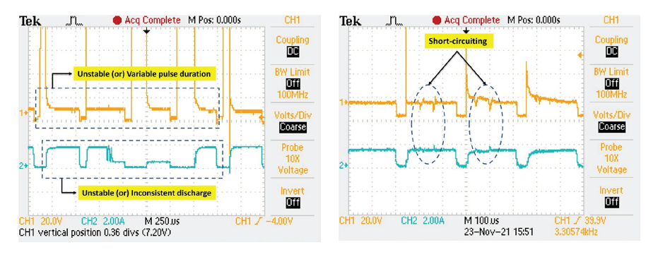
On observing the waveforms, it is evident that some ignition delay occurs as the potential is applied to breakdown the dielectric medium, and the electric discharge follows it. In conventional EDM, the occurrence of arcing and short-circuiting is more frequently observed. As the debris particles get stuck in the machining gap, the detection and retraction delay of the servo control system leads to arcing and short-circuiting phenomena. Figure 3 shows the waveforms obtained in conventional EDM at a gap voltage (10 V) and a peak current (4 A) during machining of Ti-64. The unstable (or) inconsistent discharge duration occurs due to variations in ionization time and arcing conditions. Figure 4(a) illustrates the unstable discharge occurring during EDM operation. Most unfavourable short-circuiting occurs due to the accumulation of debris near the discharge gap, leading to a direct contact between the electrodes. Figure 4(b) depicts the occurrence of short-circuiting during the discharge pulse duration.
V–I curve obtained during Maglev EDM operation.
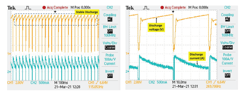
Figure 5(a) indicates that most V–I waveforms are stable during Maglev EDM operation. The absence of unstable and inconsistent pulses concludes that better control over the machining process can be achieved. Steady discharge repetitions ensure that the machining operation is better efficient than the conventional EDM. 21 The acquired V–I curves provide the discharge voltage and current values with a sample interval varying from 40 to 400 μs and a record length of 250 ms. The acquired discharge voltage and discharge current were 6.64 V and 900 mA, respectively. The duty factor was maintained at 0.95564 during the operation while producing a discharge power of around 5.5–6 W. Stable discharge pulses ensure that the gap monitoring mechanism is better than the conventional system. Figure 5(b) was used to check the pulse width of the current–voltage signal, and it was found that the pulse widths were uniform and identical. The V–I waveforms show that the newly developed Maglev EDM generates a stable and consistent discharge. The absence of arcing and short-circuiting pulses confirms that Maglev EDM provides better gap control than the conventional EDM.
Micro-hole fabrication
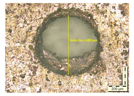
Micro-holes are primarily used for fuel injectors, biomedical filters, micro-channels for micro-fluidic operations and so on. 20 The repeated and continuous spark generation in EDM at the discharge zone between the electrodes within the narrow machining gap helps the machining operation. A small amount of material get ejected in the molten or vaporized matter. When spark comes in contact with the material surface, due to intense heating, the material is removed, leaving micro-sized craters on the surface. These continuous productions of cavities lead to the generation of the impression of the tool on the workpiece. 22 To determine the feasibility of the Maglev EDM setup for producing micro-features, a micro-hole was fabricated at a 6.64 V discharge voltage and a 900 mA discharge current with proper repetitions. Figure 4 illustrates the voltage–current characteristics curve generated during the operation. The curve shows a discharge voltage of 6.64 V with no sign of arcing or short-circuiting. Figure 6 presents the fabricated micro-hole at low discharge energy (i.e., 6.64 V discharge voltage and 900 mA discharge current) using a tungsten tool of 650 μm diameter on a 500-μm-thick nickel sheet. The density of nickel is 8.9 mg/mm3.
Fabricated micro-hole.
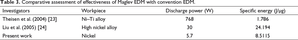
The achieved average machining rate during the micro-hole fabrication in Maglev EDM was around 40 μg/min. Table 3 presents the comparative assessment of effectiveness of Maglev EDM with convention EDM in terms of discharge power and specific energy.
Comparative assessment of effectiveness of Maglev EDM with convention EDM.
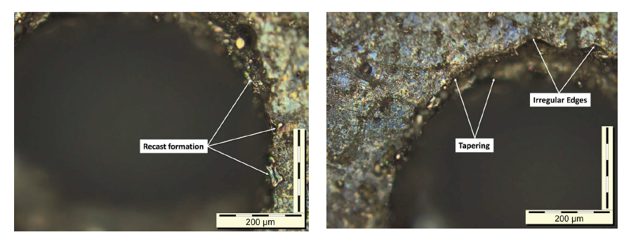
On analysing the formed micro-hole in Figure 5, the uneven edges can be easily noticed. Due to irregular tool erosion and lack of proper spark contact between the tool and the workpiece, it happens. As the tool travels through the workpiece, the lateral tool erosion creates a certain amount of circularity error. During micro-hole machining, Yu et al. (2002) observed that the presence of high debris concentration at the machining zone causes tool edge roundness. It generates abnormal discharges which produces micro-holes with uneven edges and unacceptable precision. 25 Lack of flushing also leads to resettling of molten debris on the machined zone, producing an uneven surface. 26 The presence of recast material is evident from Figures 7(a) and (b). The current research was not assisted by a flushing system which may have led to the settling of molten material on the bottom of the hole. Furthermore, the workpiece and the tool were submerged in a stagnant dielectric pool to conduct the investigation.
Machined surface. (a) Recast layer formation and (b) surface irregularity.
Surface characterization of the micro-hole. (a) SEM micrograph of the micro-hole edge and (b) EDS report of the recast layer.
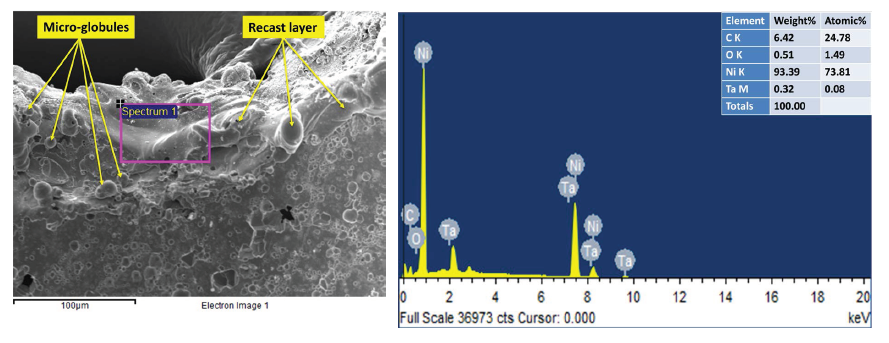
Due to sudden cooling and solidification, some portion of molten material settles on the machined surface in the form of a thin non-uniform recast layer. Figure 8 depicts the carbide layer formation at the edges of the micro-hole, in the form of micro-globules and blisters along with its elemental analysis. The breakdown of dielectric fluid and resettling of molten parent material form a thick layer at the machined zone. Wong et al. 27 defined that the recast layer gets contaminated due to material migration from the tool and dielectric fluid. These kinds of contamination may result in improving the surface properties due to the surface alloying phenomena. These carbide and oxide layers on the machined surface increase the wear and corrosion resistance of the material. Furthermore, for selective removal of the severe accumulation of solidified molten material, techniques such as electrolytic polishing 28 and selective chemical etching 29 can be performed to enhance the surface quality as per the desired application.
Tool erosion and tool-tip sharpening
During EDM operation, discrete units of material are removed from both the interacting surfaces of electrodes with each occurring discharge pulse. The amount of material erosion for a given electrode material is proportional to the discharge energy. Therefore, the resolution of work, achievable feature size and electrode erosion at each pulse occurrence are dependent on the discharge energy. 30 Hence, control over the discharge energy determines the domain of machinable size and erosion volume of electrodes. The discharge energy distribution towards each electrode depends on the polarity of the electrodes. As the dielectric gets ionized at the discharge gap when a potential is applied, the free electrons move towards the anode, while positive ions move towards the cathode. Hence, the amount of heat generated at the anode surface due to electron bombardment due to higher velocity is much greater than the cathode surface, where positive ions reach a slower pace. 31 By determining the polarity of the electrodes, the specific condition of material removal can be achieved during EDM operation. Previously, much research has been focused on utilizing the negative impact of tool erosion in EDM to better applications and advantages, one of which is a micro-tool fabrication using block EDG (BEDG), 32 micro-tool formation using self-drilled holes, 33 tool sharpening during micro-hole drilling, 34 etc.
Post-operation tool condition. (a) SEM micrograph and (b) microscopic image.
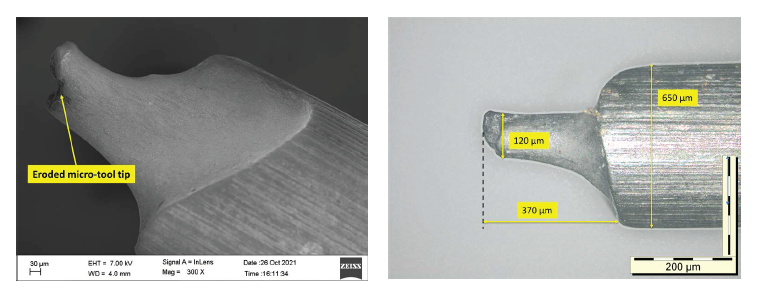
Micro-tools are used to fabricate micro-features in EDM. Basically, in the EDM process, the tool shape’s impression is achieved on the workpiece surface. Workpiece and tool wear simultaneously during the spark-erosion process, leading to micro-hole formation and sharpening of the tool. Kar et al. 35 observed the micro-tool curved wear-out section at the tip portion and the sharpening phenomena of the tool during to-and-fro motion of the tool for micro-slot fabrication. Yamazaki et al. 33 investigated the formation of micro-rods using self-drilled holes. They prepared a micro-rod of 4 μm diameter using this method and further fabricated a micro-hole of 5 μm diameter using the same tool. During the current investigation, the tool tip diameter reduced from 650 to 120 μm, as shown in Figure 9. Using this technique, micro-tools of different diameters can be easily fabricated. Egashira et al. 34 noticed the sharpening of micro-tool to produce submicron diameter micro-tools. They fabricated straight tungsten tools of 0.3 μm diameter using this technique.
Conclusion
The newly developed Maglev EDM is tested for its feasibility to fabricate micro-features in the aforementioned sections by experimentation on a thin sheet of nickel workpiece using a micro-tool made of a cylindrical tungsten rod. The process outcomes confirm its feasibility and define the novel Maglev system as better than the conventional setup. From the above observations, it can be concluded that
The novel Maglev system shows better stability and efficiency of machining than the conventional system, as observed by comparing the V–I waveforms of respective types of EDM. The fabricated micro-hole confirms the feasibility of the novel Maglev EDM to produce micro-features on the nickel sheet with an average MRR of 40 μg/min. The present system provides better gap control during machining than the servo mechanism, which is derived through the absence of arcing and short-circuiting phenomena in the V–I characteristics waveforms. Though the tool wear is an unfavourable condition, it is noticed that the tool sharpening phenomenon helps reduce the diameter of tool tips, which can be reused to produce much smaller micro-features.