
Abstract
Titanium is extensively utilized in aerospace and medical scenarios owing to its outstanding mechanical properties and corrosion resistance. Conventional machining of titanium alloys is challenging because of its innate characteristics like hardness, lofty reactivity, modest thermal conductivity and elastic modulus. Therefore, an attempt has been made to study the ease with which titanium alloy (Ti-6Al-4V) can be machined using abrasive jet machining (AJM). Machining of holes in Ti-6Al-4V was executed by incorporating a group of input parameters—air pressure, abrasive grit size and standoff distance. The output responses such as material removal rate (MRR), circularity, radial overcut (ROC) and taper angle (TA) are chosen for the evaluation of the experiment. The machining parameters are optimized for higher MRR (case 1) and for lower ROC and TA (case 2) using multi-objective grey relational analysis to choose a moderate course among the output parameters.
Introduction
In recent years, titanium has become a critical workpiece material in the production of many industrial components. The amalgamation of good strength-to-weight ratio, outstanding mechanical properties and corrosion resistance enables it to become an ideal choice for many critical applications like aerospace and medical industry. Titanium alloys are excessively used in most aircraft designs these days, and in the medical industry, titanium is an essential component in medical devices and implants used within the body. The frequently used titanium implant in the medical field is Ti-6Al-4V extra low interstitials (ELI). Though Ti-6Al-4V alloy possesses desirable mechanical properties, it also has formidable machining challenges due to lofty chemical reactivity, modest thermal conductivity and elastic modulus.1, 2 In addition to these, chattering developed during machining leads to excessive tool wear, 3 high thermal load on tool, 4 spring back effect that causes poor surface finish on the workpiece, 5 and welding of chips to workpiece leading to tool failure and workpiece damage, 6 thus making the machining of titanium alloy an arduous and tedious task. Studies had also proved that wear craters and flank wear occurs in tool due to adhesion, dissolution diffusion, abrasion and chemical attrition that occurs while machining titanium alloy. Researchers have adopted various strategies to enhance the machinability of titanium alloys by introducing high-speed machining and incorporating proper lubrication in the tool chip interface. It has been found that high-speed milling of Ti-6Al-4V using a cubic boron nitride tool escalated the magnitude of cutting forces corresponding to an increase in depth of the cut and feed rate. 7 Investigation on the effect of lubrication methods such as dry, flooded and minimum quantity lubrication showed that such methods can effectively reduce the machining zone temperature, but chip thickness was found to be more when compared to other methods. 8 Investigations on machining Ti-6Al-4V alloy using electrical discharge machining (EDM) revealed inefficient removal of debris along the hole depth 9 and created a sputtered surface due to secondary sparking. 10 In laser machining, a heat-affected zone (HAZ) was formed on the machined surface, resulting in variation of hardness and surface properties. 11 In abrasive water jet machining, it has been found that there is a formation of striated/groovy regions throughout the machined surface as a result of insufficient kinetic energy in abrasive particles. Microstructure characterization has revealed that when garnet abrasives were used, it got embedded on the surface and the continuous impingement of particles resulted in shear deformation of the surface. 12 All the processes mentioned above are still capable of machining features of prescribed sizes on Ti-6Al-4V alloy, though undesired side effects were also created.
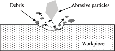
The material removal process of ductile materials using abrasive jet machining (AJM) occurs by plastic deformation, as depicted in Figure 1. The primary cutting processes involved when the abrasive particles hit the metal surface occurs in two stages: (1) particles impinge on the surface like a sharp tool and subsequently leave it while removing material in the form of tiny chips (platelets) and (2) material removal by scooping action, resulting in particles getting embedded to some depth due to decrease in kinetic energy. 13 Due to this embedment, a secondary metal cutting process with less material removal occurs, as the prior embedded particles start to divert the incoming particles. 14
Mechanism of material removal in ductile material.
AJM is commonly employed to machine hard and brittle materials. Research works have shown that AJM can also be used for machining ductile materials.15, 16 Conventional machining is not preferred for titanium alloy due to its mechanical properties and lower tool life, whereas with non-conventional machining processes like EDM and laser machining, HAZs will develop, which will affect the quality of the feature generated and also result in variation of workpiece properties. As of now, limited research work is available regarding the AJM machining of titanium alloys and hence an investigation is done in the current paper to evaluate the machinability of Ti-6Al-4V ELI by machining holes using the AJM process. The following sub-sections will explain the hole machining of Ti-6Al-4V ELI using AJM and depicts how the process parameters were optimized using a multi-objective optimization approach.
Materials and methods
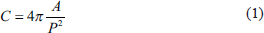
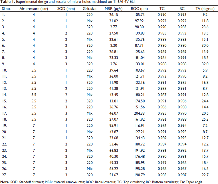
The Ti-6Al-4V ELI of dimensions 28 mm × 20 mm × 0.4 mm is taken as the workpiece sample, and silicon carbide is used as abrasive. The Taguchi L27 orthogonal array generated using MINITAB17 statistical software was used to conduct the experiments, and it carried out 27 experimental runs by utilizing the three process parameters, whose values are selected using their different levels. Table 1 displays the experimental layout and results of micro-holes machined on a Ti-6Al-4V ELI plate. The output responses considered for hole machining are material removal rate (MRR), top circularity (TC), bottom circularity (BC), radial overcut (ROC) and taper angle (TA). The responses were analyzed, and parameters were optimized using grey relational analysis (GRA). MRR is expressed in µg/s. For the machined hole, circularity is determined using Equation (1), which also forms a relation between area (A) and perimeter (P). The values of A and P are determined through ImageJ software using stereomicroscope images of the machined holes.
Experimental design and results of micro-holes machined on Ti-6Al-4V ELI.
C = 1 indicates a circular shape; if not, it deviates from circularity.
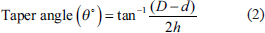
ROC and TA were measured from stereomicroscopic images and were further analyzed using ImageJ software to measure the diameters. The taper angle is found out using Equation (2), where top and bottom diameters are D and d, respectively, and h represents the work material thickness.
Experimental results and discussion
This section describes the MRR and traits of the machined hole. Figure 2 depicts the stereomicroscope images of the top and bottom faces of the micro-holes machined on a Ti-6Al-4V ELI plate for various input settings.
Stereomicroscope images of top and bottom faces of the micro-holes machined on Ti-6Al-4V ELI plate.
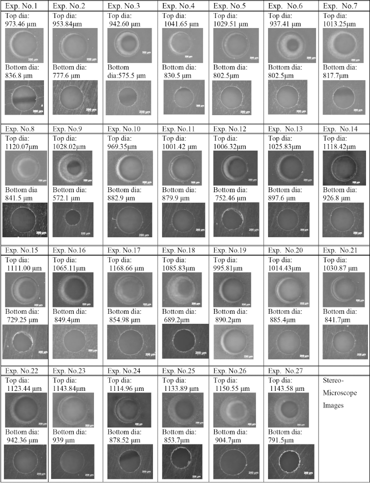
The images of the machined holes were qualitatively analyzed, and the conclusions are discussed below.
Influence of process parameters on MRR
The influence of pressure, standoff distance (SOD), and abrasive size on MRR is discussed in this section. The analysis of the experimental data shows that MRR increases with an increase in pressure. This may be attributed to the fact that higher pressure results in higher kinetic energy, causing more material removal. 17 Similarly, MRR also increases with increase in particle size. Maximum MRR (95.91 µg/s) is found to be at #220 abrasive particles, followed by Mix (66.82 µg/s) and #320 (51.67 µg/s). The volume of material removed per particle is proportional to the contact diameter and hence is a function of particle diameter. Therefore, coarse particles (#220) will have a larger impingement area on the workpiece due to their large contact diameter, thereby resulting in higher MRR during machining when compared to Mix and #320 size particles. 17
At lower pressure (4 bar), MRR values of different abrasive size particles for different SOD values are found to be nearly constant. For #220, MRR has a maximum value of 27.50 µg/s at 2 mm SOD. This indicates that better synchronization in velocity between carrier fluid and abrasives occurs at SOD 2 mm, resulting in modestly high MRR. The MRR values drop afterwards due to a hike in the flaring of jet at higher SOD. 17 For #320, the MRR value is slightly less at 2 mm SOD, and it is seen that MRR values at each SOD level are nearly the same, and not much variation in MRR is found for this abrasive size. This may be due to the fact that titanium is a hard material, and since the contact diameter of #320 is less and the pressure applied is low, the MRR will be feeble and nearly constant. For Mix, MRR increases with an increase in SOD. The Mix size particles cause an increase in MRR, indicating that coarse particles play a dominant role in MRR than finer particles due to their higher contact diameter. At medium pressure of 5.5 bar with coarse particles, the maximum MRR (41.38 µg/s) is obtained at 2 mm SOD. This shows that at 2 mm SOD, a higher value of MRR is seen due to higher impingement velocity, resulting from better synchronization between carrier fluid and abrasives, followed by a larger impingement area. Using #320 and Mix particles, the same trend of increase in MRR with SOD can be found. A high value of MRR for Mix can be attributed to better synchronization between carrier fluid and abrasive particles at 3 mm SOD. At higher pressure of 7 bar with #220 abrasives, the maximum MRR (95.91 µg/s) is found to be at 1 mm SOD and then decreases with an increase in SOD. This is because when coarse particles are used at higher SOD, particles being heavier tend to lag, resulting in high-velocity slip. This effect of particle deceleration is mostly observed at a higher pressure. 18 In addition to this effect, the consequence of flaring of the jet at higher SOD’s also contributes to a reduction in MRR, whereas for #320, MRR increases with SOD. Maximum MRR (51.67 µg/s) is observed at 3 mm SOD, irrespective of pressure values. This indicates better synchronization in velocity between carrier fluid and abrasives. For Mix, MRR increases with SOD. It has been observed that when Mix particles are used at higher pressures for machining, the influence of coarse and fine abrasive particles on MRR is nearly the same, and at lower pressures, the influence of coarse particles on MRR is more prominent than finer particles.
Influence of process parameters on ROC
Ideally, the machined hole should have the same dimension as that of the nozzle. However, after machining, it is found that the top diameter has a greater magnitude when compared to the nozzle diameter, and this defect is called overcut. ROC is found to increase with SOD. The value is found to be high irrespective of pressure, indicating the influence of flaring of jet on ROC at higher SODs. The minimum ROC (85 µm) was found to be at 4 bar pressure.
At lower pressure (4 bar) and lower SOD (1mm), the ROC values are comparatively less, as most of the abrasive particles impinge on the workpiece surface without the effect of rebounding. 19 At medium pressure (5.5 bar) using #220 and Mix abrasives, an increase in ROC resulted in a rise in the SOD value. The effect of flaring becomes an influential factor in this case. At higher pressure (7 bar), the ROC value increases with an increase in SOD for all abrasive sizes. This is due to the upshot caused by flaring found at high SOD and particle ricochet at higher pressures.19, 20 It can also be found that ROC varies with SOD non-linearly, as higher ROC values are seen at 3 mm SOD irrespective of pressure. In such cases, MRR has a more dominating role in the effect of ROC than flaring.
Influence of process parameters on the taper angle
The minimum taper angle (5.9°) is obtained at medium pressure (5.5 bar) and 1 mm SOD using #220 particles. This is because at 1 mm SOD, particles will coherently impinge the surface without any rebounding effect and hence remove the material uniformly. It has also been observed that as particle size decreases, the taper angle value increases. As a result, finer particles (#320) cause more taper than coarse particles (#220). Coarser particles retain their energy at higher depths due to inertia, while finer particles lose energy as they go deeper, resulting in an increased taper. It is also seen that as SOD increases, taper angle also increases. This is due to the effect of flaring of the jet.
For evaluating the performance characteristics, the best performance characteristic corresponds to the highest S/N ratio. Few researchers adopted the S/N ratio method for their optimization of the process parameter.21, 22 The current work deals with multiple performance characteristics, and hence an overall S/N ratio has to be evaluated for optimization purposes, making the process really arduous. This issue can be sorted out by employing the GRA method.
Determination of optimal cutting parameters
The Taguchi method is a structured method for the design and analysis of experiments in order to improve the product quality. In order to deal with scenarios where the information is scarce or undetermined, the grey system theory suggested by Deng (1982) was validated to be a useful tool.
The GRA is an effective tool to solve intricate interrelationships of various assigned performance characteristics. The analysis provides a grey relational grade (GRG), which is then used to evaluate the multiple performance characteristics. Various researchers23–26 have successfully performed GRA for optimization.
Optimization using GRA
GRA consists of three steps: data pre-processing, calculating the grey relational coefficients and calculating the GRG.
Data pre-processing
Data pre-processing is the first step in GRA. Data pre-processing involves transforming an original sequence into a comparable sequence. Experimental results are thus normalized in a range of 0–1. If the target value of the original sequence is ‘larger-the-better,’ then the original sequence is normalized as follows 27
If the purpose is ‘smaller-the-better,’ then the original sequence is normalized as follows:
where ai(k) is the value obtained after the grey relational generation, bi(k) is the current value, min bi(k) is the smallest value of bi(k) for the Kth response, and max bi(k) is the largest value of bi(k) for the Kth response.
Grey relational coefficient
The grey relational coefficient is calculated to express the relationship between the best (reference) and the actual normalized S/N ratio. The grey relational coefficient (γ0,
i
) is expressed using Equation (5).
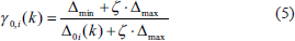
where Δ0i(k) is the deviation sequence of reference sequence Xo*(k) and comparability sequence xi*(k), that is, Δ0i (k) = |Xo*(k) − xi*(k)| is the absolute value of the difference between Xo*(k) and xi*(k), Δmin = min. min. Δ0i(k) and Δmax = max. max. Δ0i(k), and ζ is the distinguishing coefficient ζ ∈ |0, 1|. ζ is set as 0.5 in this study.
Grey relational grade (GRG)
The GRG is a weighting sum of the grey relational coefficients. GRG shows the level of correlation between the reference sequence and the comparability sequence. The overall evaluation of multiple performance characteristics (Γ0,
i
)is based on the GRG and is defined by Equation (6).

where wk represents the weight of the kth machining characteristics. In the present case, m = 27; n = 5.
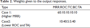
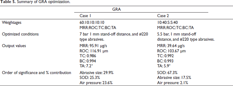
The anticipated preeminent setting for multiple characteristics relies on the weight values. However, a change in weight can alter the influence of the parameters or parameter setting. The GRA technique is used to get the perfect combination among the L27 experiments performed to achieve the desired output. In the current work, two objectives are considered during the optimization. The first objective (case 1) was to focus on finding the optimized parametric combination, which provides a higher MRR. For this, higher weightage was given to MRR and the remaining weightages were equally distributed to the other responses The second objective (case 2) was to focus on finding the optimized parametric combination, which gives minimum ROC and TA to enhance the quality of the machined hole. This was achieved by providing higher weightages to ROC and TA.
Weightages are selected as per user’s preference and is shown in Table 2. The GRG for each experiment using the L27 orthogonal array for two cases is shown in Table 3. A GRG of a higher value symbolizes that the experimental result is not far from the ideally normalized value.
Weights given to the output responses.
Grey relational grade and rank for each experiment for two aspects.
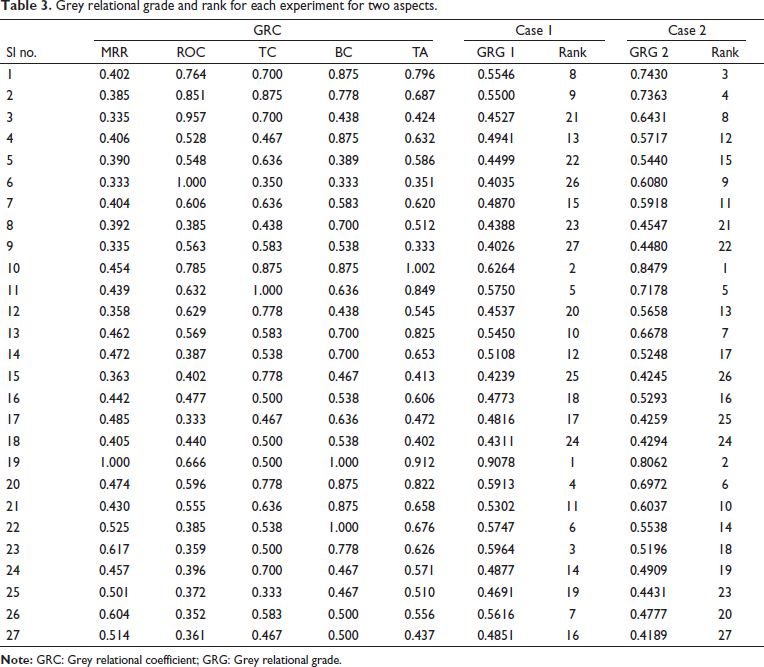
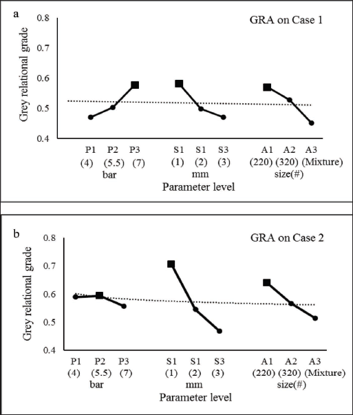
From Table 3, it is found that for case 1, the GRG value for air pressure, SOD, and abrasive grit sizes was found to be highest at level 3, level 1, and level 1, respectively. It also indicates that in order to achieve the optimal machining condition for the case 1, the machining process needs to be performed at 7 bar pressure and 1 mm SOD and using #220 type abrasives. To achieve optimal machining conditions for case 2, the machining process has to be carried out at 5.5 bar pressure and 1 mm SOD and using #220 type abrasives. Figure 3 displays the GRG graphs of various process parameters. From the graph, it is evident that P1, S1, and A3 give the highest GRG.
GRG graphs of process parameters (a) case 1 and (b) case 2.
As per the theory, the greater the value of GRG, the superior will be the multiple performance characteristics. In order to determine accurately the optimal mix of various machining parameter levels, the relative significance among different machining parameters need to be clearly evident.
Analysis of GRG
Analysis of variance (ANOVA) was executed using statistical software MINITAB17 for various GRG values to investigate the effect of process parameters on multi-machining characteristics. The ANOVA for grade values shown in Table 4 shows that the three process parameters, pressure, SOD, and grit size, significantly affect the multi-machining characteristics (p-value ≤ 0.05) under 95% confidence levels.
Analysis of variance for GRG grade values.
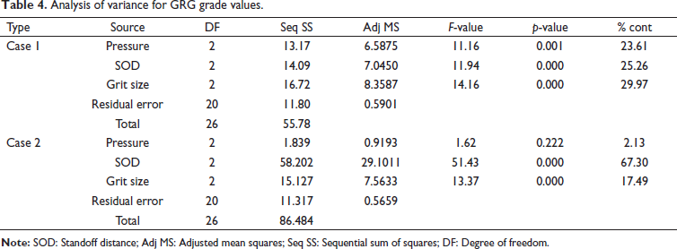
For obtaining higher MRR (case 1), the most significant process parameter is the grit size, followed by SOD and pressure. For minimum ROC and TA (case 2), the most influential factor is SOD, followed by grit size and pressure.
Verification of experiments
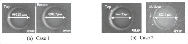
After finding the significant process parameters, the concluding stage is to verify the performance characteristics using the optimized parametric combinations. The optimized conditions and results for two cases are plotted in Table 5. From the GRA analysis, the optimized condition for case 1 is seen at 7 bar pressure and 1 mm SOD while using #220 type abrasives. Machining under such circumstances resulted in MRR of 95.91 µg/s, ROC of 116.91 µm, TC of 0.986, BC of 0.994, and TA of 7.2°, and the corresponding hole is shown in Figure 4(a). Similarly, for case 2, the optimized condition is seen at 5.5 bar pressure and 1 mm SOD using #220 type abrasives. Machining under such circumstances resulted in MRR of 39.64 µg/s, ROC of 103.67 µm, TC of 0.992, BC of 0.993, and TA of 5.9°, and the corresponding hole is shown in Figure 4(b).
Images of top and bottom faces of micro-holes at optimized conditions.
Summary of GRA optimization.
Conclusion
In the present work, machining of holes was done on biomaterial –Ti-6Al-4V ELI using the AJM process. The impact of process parameters, air pressure, abrasive sizes, and SOD, on responses, MRR, TC, BC, ROC, and TA of the holes, was analyzed in detail. The following are the conclusions of this work:
Machining of holes on Ti-6Al-4V employing the AJM process was carried out with the Taguchi L27 orthogonal array with process parameters air pressure, abrasive grit size and stand-off distance. A multi-objective GRA was utilized to evaluate the optimized condition in order to attain higher MRR and circularity and smaller ROC and TA, and ANOVA is used to find the order of significance and percentage contribution. The optimization was carried out based on two aspects. Case 1: For higher MRR, the optimized condition is seen at 7 bar pressure and 1 mm stand-off distance while using #220 type abrasives. Machining under such circumstances resulted in MRR of 95.91 µg/s, ROC of 116.91 µm, TC of 0.986, BC of 0.994, and TA of 7.2°. Case 2: For Lower ROC and TA, the optimized condition is seen at 5.5 bar pressure and 1 mm stand-off distance using #220 type abrasives. Machining under such circumstances resulted in an MRR of 39.64 µg/s, ROC of 103.67 µm, TC of 0.992, BC of 0.993, and TA of 5.9°. The relevance and percentage contribution of process parameters obtained are as follows. Case 1: Abrasive size (29.9%), SOD (25.3%), and air pressure (23.6%). Case 2: SOD (67.3%), abrasive size (17.5%), and air pressure (2.1%).
Footnotes
Declaration of Conflicting Interests
The authors declared no potential conflicts of interest with respect to the research, authorship and publication of this article.
Funding
The authors received no financial support for the research, authorship and publication of this article.