
Abstract
Wire and arc additive manufacturing (WAAM) has been demonstrated to be a pioneering process for producing small- to large-scale components with its high deposition rate and flexible deposition capability. However, WAAM has critical drawbacks, including pronounced surface irregularities and the need for secondary machining operations. The presence of surface irregularities also negatively affects the surface flatness/waviness of the as-built part and the effective wall width and height after machining. To enhance surface properties, examining the impact of WAAM parameters is necessary. As a result, this study explores the impact of wire feed speed (WFS) and traveling speed parameters on single-material WAAMed samples made of stainless steel 309L. The study examined surface irregularities such as flatness, distortion, and effective wall thickness using detailed three-dimensional scanning techniques. Hardness measurements were also conducted to evaluate hardness distribution along the deposition direction. The analysis focused on the interaction between WAAM process parameters and surface irregularities. The results indicate that the heat input is the most influential deposition criterion affecting surface irregularities, such as flatness and distortion. These findings contribute to a deeper understanding of the complex interplay of deposition parameters, providing valuable information for optimizing the WAAM processes. In conclusion, this study offers insights into the intricate dynamics of WAAM. It highlights the crucial role of WFS, travel speed, and heat input in shaping surface properties.
Introduction
Additive manufacturing (AM) has become a critical component in modern manufacturing industries due to its ability to produce complex geometries with minimal material waste and reduced lead times. One of the most prominent methods within AM for producing large-scale metallic components is Wire and arc additive manufacturing (WAAM). WAAM, an arc welding-based process, offers distinct advantages, such as high deposition rates, cost-effectiveness, and the ability to fabricate large parts, making it ideal for applications in the aerospace, maritime, and energy sectors. 1 Despite its numerous benefits, WAAM also presents challenges, particularly in terms of surface integrity, dimensional accuracy, and mechanical properties of the as-built parts. 2
A critical factor in the performance of WAAM-produced parts is their surface integrity, which includes surface roughness, flatness, and the presence of defects such as porosity or cracks. Surface roughness, in particular, has been found to significantly influence the mechanical properties of parts produced by WAAM. Studies have shown that due to high surface roughness, where the maximum peak and pit values are around 0.8 mm, the nominal and effective thickness ratio drops to 0.9, which can cause a 10% decrease in yield strength and a 20% decrease in elongation. 1 This is because surface irregularities serve as stress concentrators, which can lead to premature failure under load. Consequently, many WAAM components require secondary machining operations to improve surface quality, leading to additional manufacturing costs and extended production times. 3 Reducing the need for such secondary operations remains one of the key challenges in WAAM.
The need for secondary machining is exacerbated by the inherent distortion and flatness variations of WAAM-produced parts. These issues arise due to the high heat input and thermal gradients experienced during the WAAM process, which leads to residual stresses and geometric deviations from the desired computer-aided design model. High distortion levels make it difficult to align parts accurately for machining, often requiring three-dimensional (3D) scanning and geometric fitting prior to any secondary processing. 4 Even with advanced scanning techniques, the initial flatness values in WAAM parts can cause instability during machining, potentially leading to tool breakage and poor part quality. 5 For example, excessive flatness can result in uneven material removal during machining, which not only affects the final dimensional accuracy but also increases tool wear and production costs. 5
Flatness and surface quality in WAAM are primarily influenced by the bead geometry, which is determined by key process parameters such as wire feed speed (WFS), travel speed (TS), and current. 2 The heat input during the process, a function of these parameters, plays a crucial role in controlling the geometry of the deposited layers. Research indicates that higher TSs combined with lower current can reduce the bead width, thereby minimizing surface irregularities and improving flatness. 6 Conversely, increased heat input, achieved by lowering TS and increasing current, can lead to a more uniform deposition, enhancing flatness but potentially introducing other challenges, such as changes in microstructure and hardness. 6
The microstructure of WAAM-produced parts is highly dependent on the cooling rate, which varies across different layers due to the inherent layering process. This leads to anisotropy in the material properties, particularly in terms of hardness. Austenitic stainless steels, commonly used in WAAM, exhibit a transformation from ferritic to austenitic phases during cooling. Rapid cooling near the substrate results in the formation of hard phases such as lathy ferrite, while slower cooling in the upper layers leads to the development of softer phases, such as skeletal ferrite. 7 This variation in cooling rates and resultant microstructures causes a hardness gradient across the part, with higher hardness near the substrate and lower hardness in the upper layers. 8 Such anisotropy in hardness can affect the mechanical performance of the part, particularly in applications where uniform mechanical properties are critical.
Moreover, the interaction between WFS, TS, and heat input not only influences bead geometry but also affects hardness distribution and microstructure. While individual studies have explored the effects of WFS or TS alone, few have systematically examined their combined influence with heat input on critical performance metrics such as flatness, hardness, and distortion. 9 This lack of comprehensive understanding makes it difficult to optimize the WAAM process for both geometric accuracy and material performance.
Another challenge in WAAM is controlling distortion, which is influenced by residual stresses that develop during the deposition process. These stresses arise from the non-uniform cooling of each deposited layer, resulting in thermal gradients that cause the part to warp or distort. This phenomenon is particularly problematic in larger parts, where the cumulative effect of residual stresses can lead to significant deviations from the intended geometry. 10 To minimize distortion, it is crucial to optimize the WAAM process parameters, particularly the heat input and deposition strategy, to ensure a more uniform cooling and reduce the thermal gradients across the part. 3
Recent studies on WAAM-produced stainless steel 309L components highlight the importance of performance metrics such as surface quality, hardness distribution, flatness, and distortion. For instance, the bead geometries, influenced by TS and wire feed rate, play a crucial role in determining surface quality and flatness in WAAM parts. 11 Additionally, the microstructure and hardness distribution across the layers vary due to differing cooling rates, leading to anisotropy in mechanical properties. 12 The top layers tend to have coarser structures with lower hardness, while the bottom layers exhibit finer grains and higher hardness. 13 Furthermore, studies have demonstrated that optimizing process parameters such as heat input and deposition speed can significantly reduce residual stresses, minimizing distortion and improving the dimensional accuracy of the parts. 14 Addressing these performance metrics is essential for enhancing the overall quality and reliability of WAAM-produced stainless steel components.
This study aims to address these gaps by investigating the combined effects of heat input, WFS, and TS on critical performance metrics such as surface quality, hardness distribution, flatness, and distortion in parts produced using stainless steel 309L in a 20-layer WAAM deposition process. By exploring the interaction between these parameters, this research seeks to optimize the WAAM process for improved surface integrity and mechanical performance, contributing valuable insights for industrial applications.
Materials and methods
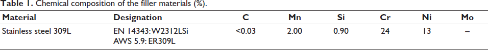
In this study, the WAAM process was employed to produce multi-layered stainless steel parts. The WAAM system consisted of two TransPuls Synergic 4000 power sources (Fronius International GmbH, Wels, Austria) and a twin-torch system mounted on a UR10e six-axis robotic arm (Universal Robots A/S). This setup allowed precise control of the welding parameters and deposition path, ensuring consistent layer formation throughout the process. The filler material used in the deposition was a 1.2-mm diameter solid-wire electrode made of stainless steel 309L, with its chemical composition shown in Table 1. The substrate material was stainless steel 304, which is commonly used in industrial applications requiring good weldability and corrosion resistance.
Chemical composition of the filler materials (%).
A shielding gas of pure argon was used to maintain an inert atmosphere during the deposition process. The gas flow rate was set to 20 L/min, as suggested in previous studies to prevent oxidation and ensure stable arc characteristics. 15 The WAAM process was conducted using the zig-zag deposition method, a technique in which the welding direction alternates between each successive layer. This method helps counteract the thermal gradient effects typically observed during unidirectional welding, where thermal accumulation in one direction leads to warping and distortion. The zig-zag method mitigates these issues by balancing the heat distribution across layers, reducing the likelihood of deformation.8, 10
Parameter selection and deposition strategy
The WAAM process parameters were selected based on an extensive literature review and previous experimental work with stainless steel 309L. WFS and TS were identified as the two critical factors influencing the deposition quality, surface irregularities, and geometric accuracy. The selected parameter combinations are presented in Table 2, where each case represents an edge point within the process window determined for stainless steel 309L under argon shielding conditions. 6
WAAM deposition parameters.
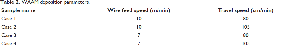
During the deposition, the effect of WFS and TS on bead geometry and surface quality was evaluated. Each parameter set was applied to produce 20-layer samples, ensuring that sufficient data could be collected to evaluate the influence of each combination on the final part quality. As is common in WAAM processes, heat accumulation during deposition caused the initial layers to be thicker than subsequent layers. Due to total heat accumulation, the cooling rate of each layer added along the build direction decreases, and the solidification process becomes longer. In other words, the first layers are wide as they undergo rapid solidification with a high cooling rate. Since the upper layers remain in the solidification process for longer, they tend to flow over the previous layer, decreasing the layer width. This trend stabilized after the 10th layer, where the thickness became uniform. 10 Although heat continues to accumulate after the 10th layer, the decreases in the cooling rate become almost negligible, so the solidification process of each added layer is similar.
Heat input calculation
The heat input (HI), which directly affects bead geometry and part microstructure, was calculated using the following equation:
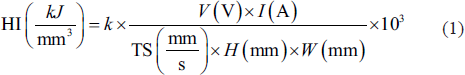
Where
V: arc voltage (V) I: welding current (A) TS: travel speed (mm/s) H: bead height (mm) W: bead width (mm) k = 0.8: thermal efficiency factor (as per EN 1011-1 standards)
The voltage (V) and current (I) values were monitored and recorded in real time during deposition to ensure accurate heat input calculations. The bead heights and widths were measured using a cross-sectional analysis of the deposited layers. These measurements, combined with TS data, were used to calculate the heat input for each parameter set.
Geometric and surface analysis
After deposition, the parts were scanned using a 3D scanner (ATOS Compact Scan, GOM Metrology) to capture detailed surface geometry and assess dimensional accuracy. The scanned data allowed the parts to be fitted into a rectangular prism, filling the irregularities formed on the surface due to the nature of the WAAM process. This fitting method enabled the extraction of critical geometric parameters such as flatness (B, C), effective wall thickness (D), and effective wall height (E) from cross-sections taken at 0.1 mm intervals along the deposited walls (as shown in Figure 1). The measurements were taken at a reference height of 80 mm from the base, and the maximum flatness values and minimum wall thicknesses were recorded for further analysis.
Flowchart of the experimental study, (a) deposited wall workpiece, (b) 3D scanning, (c) deviation of scanned data from nominal data, (d) determining the flatness and distortion values.
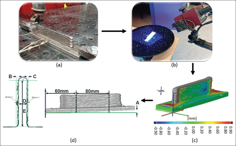
The maximum distortion values (labeled as A in Figure 1) were also determined by fitting the substrate geometry into three planes and measuring the deviations. The combination of flatness, wall thickness, and distortion values provided a comprehensive understanding of how different parameter sets affected the final part geometry.
Microstructural and hardness analysis
After the 3D scanning process, the parts were sectioned at the 60-mm region (as shown in Figure 1) to allow for microstructural analysis of the 1st, 5th, 10th, 15th, and 20th layers. Each section was etched using Kalling’s No. 2 solution (composed of 5 g copper(II) chloride, 100 mL hydrochloric acid, and 100 mL ethanol) to reveal the microstructural features of the layers. The etched cross-sections were observed under a digital microscope (KH-8700, Hirox Corporation, Tokyo, Japan) to examine the distribution and density of ferrite phases within the deposited material. The formation of these phases is strongly influenced by the cooling rate in each layer, which in turn is affected by the heat input and layer buildup during the WAAM process.7, 16
To evaluate the hardness distribution across the layers, a Vickers hardness test (HV1) was conducted in accordance with EN ISO 6507-1 standards. A load of 1 kg was applied for 13 seconds at multiple points across each layer to obtain a comprehensive hardness profile. These hardness values provided insight into the anisotropic mechanical properties of the WAAMed parts, which result from the varying cooling rates and microstructural changes that occur as successive layers are deposited.8, 17
The combination of geometric analysis, microstructural evaluation, and hardness testing offered a thorough investigation of how WFS, TS, and heat input interact to affect the overall quality of WAAM-produced parts. These findings will help inform parameter optimization for future industrial applications of WAAM, particularly in achieving higher surface quality and mechanical performance with reduced postprocessing requirements.
Results and discussion
WFS and TS are critical parameters that determine the quality and performance of parts produced through WAAM. Numerous studies have emphasized the importance of these parameters, particularly in relation to surface irregularities, heat input, and mechanical properties such as hardness distribution. 17 In this study, 20-layer stainless steel 309L structures were deposited using various combinations of WFS and TS to examine their effects on surface flatness, distortion, and hardness. Additionally, the heat input associated with each parameter combination was calculated and linked to the observed bead geometry and mechanical properties of the parts.
Surface irregularities: Influence of wire feed speed and travel speed
The formation of surface irregularities in WAAM is largely determined by the solidification behavior of the filler material. The rate of solidification and the shape of the deposited layers are influenced by two primary factors: heat input, which is dependent on the welding voltage and current, and the bead width, which is controlled by the interaction between WFS and TS. Bead width plays a crucial role in determining the surface profile, including flatness and effective wall thickness.
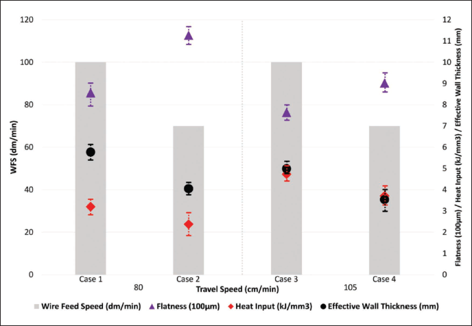
For example, under constant TS, increasing WFS introduces a higher volume of material into the weld pool per unit area, which results in slower cooling and a wider bead. Conversely, with lower WFS, the material cools more rapidly, producing a narrower bead with potentially greater height. This relationship between cooling rate, bead width, and bead height is central to understanding the resulting surface irregularities in WAAM. Figure 2 provides a graphical representation of how WFS and TS affect heat input, flatness, and effective wall thickness in this study.
Effects of WFS and TS on flatness, heat input, and effective wall thickness.
Effect of wire feed speed on surface quality
As depicted in Figure 2, higher WFS values consistently led to increased heat input across different TS levels. This increase can be attributed to the need for higher welding voltages at higher WFS, as more filler material requires a stronger arc to ensure proper fusion.9, 18 While WFS is not a direct factor in the heat input formula, its effect is reflected in the total energy absorbed by the weld pool, which ultimately influences the bead geometry and surface quality. Specifically, increasing WFS causes the effective wall thickness to rise, as more material is deposited per unit time, resulting in a wider bead. 8
Interestingly, the data revealed that higher flatness values were achieved with lower heat inputs and lower effective wall thickness values. This finding contradicts the traditional understanding that higher heat input improves surface flatness by allowing for smoother solidification. However, in this study, the rapid cooling associated with lower heat input led to faster solidification, which may have limited the deformation caused by thermal gradients during deposition. Empirical evidence from previous studies supports the hypothesis that faster cooling times can improve flatness by preventing the buildup of residual stresses. 8 Additionally, techniques such as magnetic arc control have been shown to enhance heat input and improve flatness, though these methods were not employed in the current study.3, 19
Effect of travel speed on surface quality
While heat input is generally expected to decrease with increasing TS (as per Equation 1), the results indicated that heat input actually increased at higher TS for the same WFS values. This can be explained by the reduced deposition volume at higher TS. As the torch travels faster across the substrate, less filler material is deposited per unit area, resulting in a narrower bead width. This narrowing of the bead increases the heat input per unit area, as more energy is concentrated over a smaller surface.6–9
The relationship between TS and heat input has been previously reported in the literature, though earlier studies primarily focused on empirical observations without considering the precise geometric changes in the bead. 17 The current findings emphasize the importance of considering both the geometric dimensions of the bead and the set parameters when calculating heat input. As TS increases, the resulting decrease in bead width leads to higher heat input despite the expectation that higher TSs would reduce heat transfer to the part.
At higher TS, the reduced deposition volume also results in a lower effective wall thickness, as less material is deposited during each pass. However, the prolonged cooling times associated with higher heat input counteract this reduction, leading to a decrease in flatness as solidification is extended. This finding suggests that while higher TS can reduce material buildup, it also introduces additional cooling challenges that negatively affect surface flatness.
Distortion and residual stress accumulation
Distortion is a critical issue in WAAM, particularly for large or complex structures where the cumulative effect of heat input can lead to significant residual stresses. These stresses arise from the uneven cooling and solidification that occur as each successive layer is deposited, resulting in thermal expansion and contraction cycles that cause the part to warp. The degree of distortion is influenced by both the effective wall thickness and the total heat input, which together determine the thermal gradients within the part.
Figure 3 shows that distortion tends to increase with effective wall thickness, regardless of the total heat input. This can be explained by the fact that thicker walls have greater thermal mass, which leads to longer cooling cycles and higher residual stress accumulation. As a result, parts with higher effective wall thickness are more susceptible to distortion, even if the total heat input is relatively low. This finding is consistent with earlier studies, which have shown that thicker walls are more prone to warping due to the increased thermal expansion during solidification. 4
Effects of effective wall thickness and heat input on distortion.
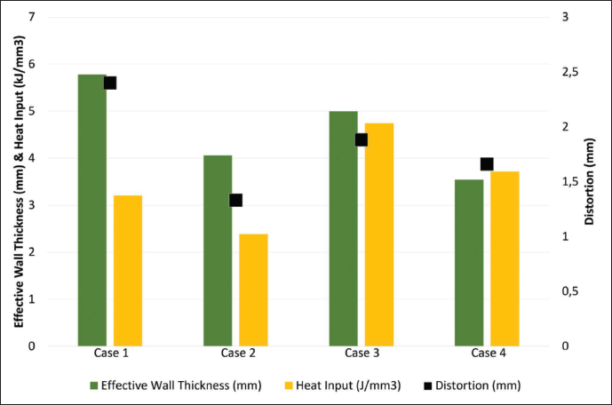
In contrast, Case 1 exhibited significant distortion despite having a lower heat input than the other cases. This can be attributed to the high effective wall thickness in this case, which underscores the importance of wall geometry in determining distortion. Even with reduced heat input, thicker walls experience greater thermal stresses, leading to more pronounced warping. Figure 3 illustrates the changes in effective wall thickness across all cases for the comparison between the cases.
However, Case 2 presented a notable exception to this trend, with lower distortion despite having a similar effective wall thickness to Case 4. The key difference lies in the lower heat input in Case 2, which allowed for faster cooling and reduced thermal expansion, thus minimizing distortion. These findings suggest that for parts with similar effective wall thickness, lower heat input and higher TS are preferable to reduce the risk of distortion.
Hardness distribution across layers
The hardness distribution across the deposited layers was measured to assess the mechanical performance of the WAAM parts. Hardness tests were conducted on the 1st, 5th, 10th, 15th, and 20th layers, providing a comprehensive profile of how the microstructure evolved with successive layers. The results, as shown in Figure 4, indicate that the hardness was highest in the initial layers, with a gradual decrease observed as more layers were deposited.
Hardness distribution along the workpieces.
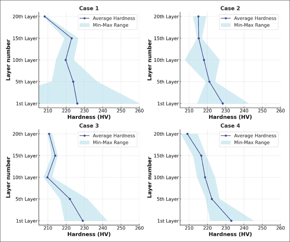
The high hardness in the first layer can be attributed to the rapid cooling rate, which restricted the ferrite-to-austenite transformation and promoted the formation of lathy ferrite. Lathy ferrite is known for its high hardness compared with other ferrite phases such as skeletal ferrite and granular ferrite, which form at slower cooling rates.7, 16 As deposition progressed, the heat accumulation increased, leading to slower cooling cycles in the upper layers. This resulted in the formation of softer phases such as skeletal and granular ferrite, which explains the observed decrease in hardness in the 5th, 10th, 15th, and 20th layers. Figure 5 shows the differences in ferrite types by layer.
Phase transformation in different layers.
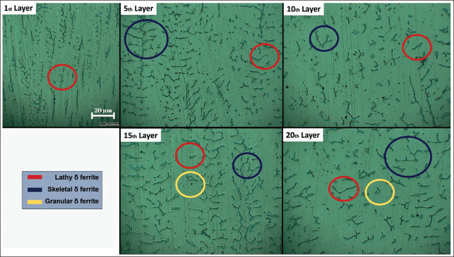
Quantitatively, the hardness dropped by 24.2%, 6.8%, 7.5%, and 12.3%, respectively, from the substrate to the topmost layer. This decrease is consistent with the progressive softening of the material as the cooling rate decreases, allowing for the full transformation of the austenitic phase into granular ferrite in the upper layers. 16 Granular ferrite, which forms at lower cooling rates, significantly reduces the hardness of the material compared with the harder lathy ferrite phase found in the lower layers.
While the literature often attributes variations in hardness to differences in heat input, many studies calculate heat input based only on the welding machine’s set voltage and current without considering the actual deposition geometry or material distribution. 17 This study’s approach of incorporating bead geometry into the heat input analysis provides a more accurate understanding of how cooling rates and thermal gradients affect the final hardness distribution.
Implications for process optimization
The results of this study highlight the complex interplay between WFS, TS, and heat input in determining the quality of WAAM-produced parts. Achieving optimal surface quality, minimal distortion, and consistent mechanical properties requires careful balancing of these parameters. Based on the findings, the following recommendations can be made for optimizing the WAAM process:
Lower WFS combined with higher TS should be used to minimize distortion and reduce residual stresses, particularly for thicker walls.
Rapid cooling at lower heat inputs should be favored to improve flatness and reduce surface irregularities, as faster solidification helps prevent material buildup and warping.
The hardness distribution should be carefully controlled by adjusting the cooling rates through parameter tuning, particularly in applications requiring uniform mechanical properties across multiple layers.
Conclusion
This study investigated the combined effects of WFS, TS, and heat input on key performance metrics such as surface irregularities, hardness distribution, distortion, and microstructure phase formation in multi-layer WAAM-produced parts. The main findings from the experimental results are summarized as follows:
WFS and heat input: Although the heat input formula does not directly include WFS, an increase in WFS indirectly raises the heat input. This occurs because a higher WFS introduces more filler material into the weld pool, necessitating an increase in the applied voltage, which, in turn, raises the total heat input. Therefore, WFS significantly influences the thermal conditions during deposition, despite not being explicitly accounted for in the heat input equation.
Bead geometry: As WFS increases, both bead width and effective wall thickness increase due to the higher volume of material deposited per unit area. This results in a more pronounced bead profile, which directly affects the geometric characteristics of the final part.
Flatness and solidification: The best flatness values were achieved at lower WFS values, as lower heat input promotes faster cooling and more rapid solidification. This suggests that controlling heat input through WFS adjustment is critical for minimizing surface irregularities and achieving smoother surfaces.
TS and heat input: Contrary to conventional wisdom, increasing TS does not always reduce heat input. While higher TS reduces the amount of material deposited per unit area, it also narrows the bead width, concentrating heat in a smaller area and effectively raising the heat input. As a result, the assumption that “high TS results in lower heat input” is no longer valid in this context, as the bead geometry must be considered alongside the set parameters.
Flatness improvement: Increasing TS at constant WFS was found to reduce effective wall thickness and improve flatness. Therefore, higher TS can be used strategically to enhance surface quality by reducing material buildup and achieving more uniform deposition layers.
Distortion: Bead width plays a significant role in triggering distortion. Wide beads, typically obtained with high WFS and low TS, lead to increased distortion due to greater thermal gradients and residual stress accumulation. In contrast, narrower beads formed at lower WFS and higher TS result in reduced distortion, improving the dimensional accuracy of the parts.
Optimizing parameters for lower distortion: To minimize distortion, the optimal parameter combination involves low WFS and high TS. This combination ensures lower heat input per unit area, faster cooling, and reduced residual stress, resulting in more geometrically stable parts.
Hardness distribution: Due to the varying cooling cycles across the layers, the part exhibited a hardness variation of up to 24.2% from the substrate to the top region. This variation is primarily driven by differences in microstructural phase formation across the deposited layers.
Microstructural phases and hardness: In areas close to the substrate, the rapid cooling led to the formation of lathy ferrite, a phase associated with high hardness. In contrast, the upper layers, which cooled more slowly, allowed for the formation of skeletal and granular ferrite. These phases are softer, leading to a decrease in hardness as the part transitions from the substrate to the top layers.
In summary, this study highlights the importance of optimizing WFS, TS, and heat input to achieve better surface quality, reduced distortion, and more consistent mechanical properties in WAAM-produced parts. The findings underscore the need for a holistic approach to parameter selection, considering not only the set values but also their effects on bead geometry, solidification behavior, and microstructural transformations. Future studies should focus on real-time monitoring of these parameters and exploring additional factors such as shielding gas composition and torch positioning to further refine the WAAM process.
Footnotes
Acknowledgment
The authors acknowledge the help of the research group members in conducting experiments.
Data statement
The raw data being reported in this article can be obtained from the corresponding author upon reasonable request.
Declaration of Conflicting Interests
The authors declare that they have no known competing financial interests or personal relationships that could have influenced the work reported in this article.
Funding
The authors disclosed receipt of the following financial support for the research, authorship, and/or publication of this article: Support for this work comes from the project “Advanced Processing of Additively Manufactured Parts II (Ad-Proc-Add II)” (HBC.2021.0278) funded by Agentschap Innoveren en Ondernemen.