
Abstract
Among all the hybrid machining techniques, electrochemical discharge micro-drilling (ECDMD) is the most current and challenging process. With no residual stress, it is utilized to create micro-features of accurately and precisely holes on electrically non-conductive composite materials that are either hard or rigid. Micro-features of electrochemical drilling (ECD) and electro-discharge drilling (EDD) processes are integrated into an ECDMD process, and its principle is based on the electro-discharge mechanism. Comparing the ECDMD configuration to traditional drilling, it is more appropriate for creating precise holes in non-conductive, sustainable materials. This article focuses on the fundamentals of the ECD micro-drilling process by using a tabular analysis to review the experiments conducted by earlier researchers. Furthermore, recent studies address how input parameters impacted the features of the drilling process, and the fishbone diagram aids in representing the process responses of the ECDMD method. Based on a thorough review of the literature, pie charts and line diagrams have been utilized to analytically depict the range of non-conductive sustainable materials, year-by-year publications and research potential.
Nomenclature
A: Ampere
DC: Direct current
ECAM: Electrochemical arc machining
ECDD: Electrochemical discharge drilling
ECDM: Electro-chemical discharge machining
ECM: Electrochemical machining
ECSM: Electro-chemical spark machining
EDM: Electro-discharge machining
EWR: Electrode wear rate
IEG: Inter-electrode gap
MEMS: Micro-electromechanical system
MPa: Mega Pascal
MRR: Material removal rate
µF: Microfarad
µm: Micrometer
µs: Microsecond
ms: Millisecond
Ra: Surface roughness
RM-ECDD: Rotary mode electrochemical discharge drilling
RPM: Revolution per minute
SACE: Spark assisted chemical engraving
SEM: Scanning electron microscope
TWR: Tool wear rate
V: Voltage
Ф: Diameter
Introduction
Electrochemical discharge micro-drilling (ECDMD) is a more common approach for creating drill holes in a range of non-conductive sustainable materials, even if they are fractured. The sophisticated ECDMD mechanism is now being investigated, and different experimenters are overseeing numerous output reactions. During ECDMD, the tool within the classification is worn by drilling micro-features the electro-discharge and electrochemical machining processes. Using the machine with non-conductive sustainable materials is made more challenging by the strong electrical discharge produced immediately above the electrode surface during the electrochemical reaction heat breakdown 1 . The low cost, improved performance, and respectable elasticity are processed using a specially designed. This might help preserve sustainable dielectric non-conductive materials, such as hard and brittle components. The need for sustainable, non-conductive materials has increased due to the growth of electromechanical system fluidics automation and growing technical demands. Numerous studies are carried out to improve machining process accuracy, modify motion control methodology, and optimize process parameters by adjusting motion control using several techniques2–4. Many scientific restrictions allow for the more efficient usage of certain non-metallic compounds. Therefore, drilling ECDM has been applied in many different sectors in recent years. Enhancing the eroding action of the electrodes is the concept of controlled ECDM micromachining. Moreover, excellent machining capabilities for hard, non-conductive sustainable materials are provided by ECDM5–7. The efficiency of ECDM drilling on stainless steel was effectively improved by Huang et al. using pure water as the electrolyte 8 .
For ECDM of glass and polymer-based composite materials, several researchers have investigated the significance of various electrolytes in their research articles. To improve the MRR, the experiments were conducted to produce holes in e-glass fiber reinforced polymer composite with NaOH and KOH electrolytes9, 10. By utilizing Taguchi’s gray relational analysis to optimize process factors, Antil et al. 11 discovered better machining results for SiC-based polymer composites. In ceramic machining, abrasive rotating tools outperform static hollow electrodes. Chak and Rao 12 observed that abrasive tools have an improved capacity for slicing. In addition, it was demonstrated by Laio et al. that a sodium dodecyl sulfate (SDS) electrolyte created greater numbers of bubbles than a solution that had no SDS, which enhanced the quality of the machining process 13 . Singh et al. highlighted the efficiency of employing silicon-carbide composite materials based on aluminum in the rotating electrode ECDM method, exhibiting significant enhancements over sinking ECDM 14 . Furthermore, adding borosilicate glass to the drilling ECDM method reduced operating costs and increased machining productivity, while raising the electrolyte concentration resulted in a higher material removal rate (MRR). Workpieces made of glass are important in production and are employed in the micro-electromechanical systems (MEMS) industry15–17. In contrast to conventional techniques, Kurafuji and Suda’s 1968 composite machining process made it possible to drill glass workpieces during ECDM more quickly 18 . Because of this area’s effectiveness in drilling ECDM applications, there has been a lot of interest in it from researchers. According to Razfar et al., removal rates on glass workpieces were greater when utilizing a vibrating tool during the drilling ECDM process compared to a stationary tool 19 . In order to provide accurate feed rate recommendations for glass drilling ECDM, Arab and Dixit concentrated on analyzing the feed rate of rotating tools 20 . In opposition to coatings during ECDM, Kang and Tang investigated the difficulties of using electric discharge to drill superalloy substrates 21 . In drilling ECDM, Gupta et al. looked at process variables for non-conductive sustainable materials and found that pulse duration significantly affected the machining reactions. Additionally, they discovered that machining efficiency was greater when NaOH was used as the solution as opposed to NaCl 22 . In contrast to drilling EDM, researchers employed salt solutions with lower conductivities to improve machining efficiency and surface quality during tubular electrode-based drilling ECDM. At high speeds, this method enhanced material removal mechanisms 23 . In order to avoid short circuits, limit taper angles, and maximize drilling depth, Geng et al. proposed a backflush configuration to the ECDM drilling technique for nickel materials 24 . In ECDM drilling of nickel-based superalloys, Zhang et al. investigated a novel technique to remove precast layers by utilizing a variety of fluids. They confirmed through theoretical and experimental analysis that external flushing decreased the radius of stray corrosion 25 . Arab et al. completed theoretical and experimental investigations of various inter-electrode gaps (IEG) for both potassium hydroxide and sodium hydroxide electrolytes in order to investigate the influence of several variables upon drilling electrochemical conductivity 26 . In order to maximize tool wear and cutting depth, they suggested modifying IEG. Furthermore, a low-cost technique was created to use drilling ECDM to drill steel cavities with a diameter of less than 1 mm. In order to guarantee the smooth drilling of small non-conductive materials and to efficiently remove detritus from the machining surface, this method uses a spring arrangement 27 . Using the orthogonal array of the Taguchi L27 approach, Pawar et al. 28 assessed the drilling ECDM process on soda-lime material and discovered that the most important variables for obtaining the ideal machining depth and hole diameter were the speed of rotation and applied voltage. It has also been discovered that adding abrasive powder to the electrolyte improved machining performance, with ceramic-based abrasives yielding better results than standard electrolytes in drilling blind holes in soda-lime glass 29 .
A newly designed drilling ECDM setup featuring an enhanced feeding mechanism was developed to facilitate deeper drilling in glass workpieces, effectively increasing machining depth through improved contact force 30 . Heat-affected zones within the hole surface can diminish machining efficiency, but using pulse voltage helps mitigate thermal damage and boosts overall performance 31 . Geng et al. presented a comprehensive study on the application of high-speed ECDD for fabricating film cooling holes in nickel-based single-crystal super alloys used in turbine blades. They focused on understanding the machining mechanisms, observing surface morphology evolution, and developing a visual simulation model to optimize machining parameters 32 . Harugade et al. explored the integration of magnetic flux density and high-speed tool rotation in the ECDD process for machining glass. They evaluated the performance analysis of MRR and entry hole overcut for varying voltages, tool rotation speeds, and feed rates using magnetic field–assisted high-speed ECDD 33 . The properties of the discharge in ECDM were also investigated using high-speed imaging technology. A comparison was made between the real-time discharge current and the discharge photographs that were taken 34 . In the analysis of hole diameters obtained in ECDM of Al2O3, Chak and Rao emphasized the benefit of pulsed DC power sources over continuous DC in minimizing surface cracks during the trepanning process 35 . Furthermore, by maximizing voltage, electrolytic concentration, and tool speed, it was discovered that utilizing a spinning copper tool electrode in soda-lime glass ECDM improved MRR, machining dimension, and diameter of holes 36 . Utilizing deionized fluid as its electrolyte, Dong et al. performed rapid ECDD and EDM studies on a beryllium–Cu alloy. They found that fast ECDD produced better machining results and less tool wear than EDM 37 . Likewise, using pure water as electrolyte in high-speed electrochemical direct metal bending of stainless steel enhanced hole quality and decreased tool wear 38 . An inventive revolving tool electrode design was used to solve taper problems in glass made from Pyrex during ECDM, utilizing pulse voltage to reduce thermal cracks and enhance machining quality 39 . Singh et al. used the L27 orthogonal array for experiments on silicon wafers in ECDM with rotating tools, achieving notable improvements in overcut (1.40%) and hole circularity (2.44%) by fine-tuning process parameters 40 . Changes in voltage and feed rate affected the management of hole taper; in revolving tool-based ECDM processes, the best parameter settings improved surface quality 41 . Super alloys are the anode that is used in the ECDD, and Xu et al. presented a novel method of transferring electrolyte through a tube of brass tool electrode, which serves as the negative electrode 42 . They improved the surface quality and produced less tooling wear while making a 0.5-mm deep hole in the workpiece compared to the EDM procedure. The results showed that, in comparison to ECDD, RM-ECDD significantly increased the aspect ratio 43 .
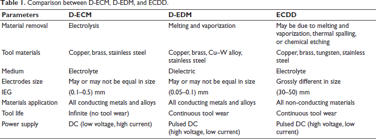
ECDD process, a hybrid of drilling (D)-ECM and drilling (D)-EDM, is optimized with a tabletop setup featuring various components. However, ECDD is appropriate for electrically non-conductive materials, whereas D-EDM and D-ECM are appropriate for electrically conductive materials 6. Although D-EDM offers higher MRR, its thermal nature leads to recast layers and microcracks, making it unsuitable for delicate as well as heat-sensitive micro-components. D-ECM avoids thermal effects but struggles with non-conductive materials. ECDMD, by combining electrochemical and discharge actions, balances MRR and surface quality, particularly in micro-drilling of hard-to-machine ceramics or composites, making it ideal for biomedical and MEMS applications44–47. The basic similarities and differences among D-ECM, D-EDM, and ECDD are tabulated in Table 1. RM-ECDD also integrates EDM and ECM, flushing with salt solution internally and deionized water externally, significantly reducing stray corrosion and recast layer formation in machined holes48–50. ECDD is used to machine N-BK7 glass, employing the Taguchi method for modeling and optimization 51 . ECDD offers high-quality aerospace manufacturing without recast layers. Introducing BF-ECDD, using continuous backside liquid flow, resolves stability and surface quality issues in drilling 52 . Since vertical vibrations facilitate fluid pressure pulsation for homogeneous reactions, VAECDD is proposed as a solution to ECDD problems. Optimal results occur at 40 kHz and 0.7 µm, yielding over 97% recast layer removal, proving efficient for high-quality hole machining 53 . ECDD offers efficient machining for turbine blade cooling holes, but breakthrough detection is challenging. A novel VSAV-based method enhances stability, achieving 100% accuracy in experimental validation and optimizing overfeeding distances for stable recast layer removal54, 55. Voltages over 45V lead to cracks and heat-affected zones, confirmed by SEM. Electrolyte concentration primarily impacts MRR, while DC voltage significantly affects overcut56–60.
Comparison between D-ECM, D-EDM, and ECDD.
This study looks at exploratory studies on a range of sustainable workpiece materials that are electrically non-conductive, as well as the effects of multiple electrolytes on the drilling ECDM operation. A fishbone diagram shows significant results and how variables related to the process affect various reactions. Additionally, the extent of possible future work and research opportunities has been emphasized in the parts that follow. Lastly, it identifies and presents the research potential for future investigations.
Working principles of the ECDMD process
In-house ECDMD is ideal for machining workpieces that are stiff, brittle, and electrically non-conductive since it integrates methods from both D-EDM and D-ECM. In the ECDMD technique, two electrodes are spaced 30–55 mm apart and have varying diameters. The surface area of the cathode, or smaller electrode, is bigger than that of the anode, or larger electrode, by a ratio of 1:10061, 62. Hydrogen bubbles emerge on the cathode tool’s surface when it is dipped two to 3 mm into the electrolyte, and an expanded electrode holds on to oxygen dioxide produced during procedure of electrolysis 63 . One of two supply types, DC or vibrating DC electricity, can be used to complete the circuit. They feature modest current limitations, as much as 15 A with elevated voltage ranges of (70–140) V64–66. A thorough illustration D-ECDM procedure is shown in Figure 1.
Schematic diagram of the ECDMD process.
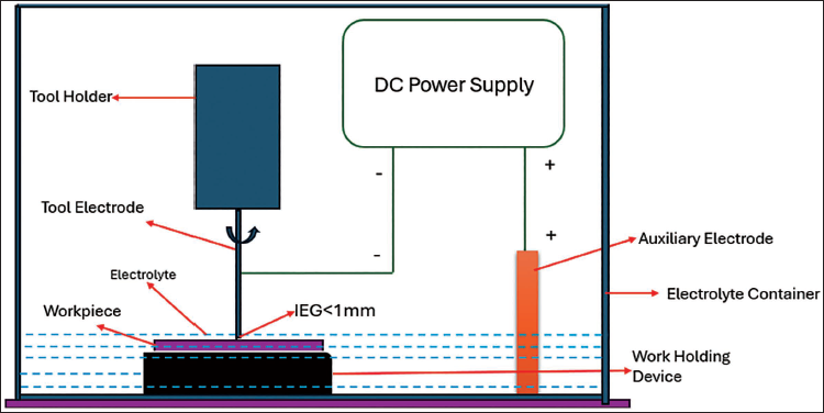
According to the law of Ohms, the reduced electrode suffers higher current intensity than the auxiliary electrode because of its smaller surface area. This can lead to an electrolyte temperature of up to 40°C–60°C. Bubbles of gas containing hydrogen occur in the cathode area when the voltage being applied exceeds the rupture voltage. There is a layer of high current resistance as a result of this conductive bubble bridge. This is why the spark ignites when the depletion voltage is less than the voltage being applied. Heating and evaporating the material while it is near the spark region of the tool and fluid allows for its extraction of work. To ensure the removal of by-products from electrolyte, a well-organized flushing method is required, along with an efficient drainage system to transfer the used electrolyte to the reservoir. It is also feasible to reuse the electrolyte, but doing so will require a suitable filtration and pumping setup. Different types of minerals, such as NaCl, sodium hydroxide, potassium hydroxide, sodium nitrate, and H2SO4 solution, can be utilized for conducting experiments on a range of electrical non-conductive components, akin to ceramics, quartz, and composites67, 68.
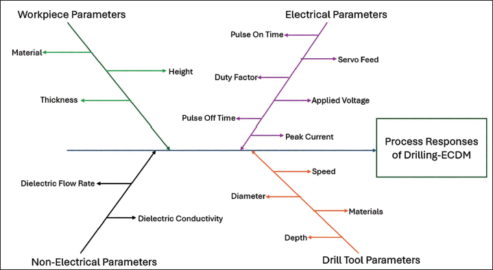
ECDM technique is called by several names, such as ECAM, SACE, and ECSM, which adds to its sophistication. Since the process depends on intricate processes, ECDM incorporates a number of engineering and scientific disciplines. Therefore, it is impractical to attempt to develop an extensive framework that describes every aspect of the process in detail. There are various configurations for the ECDM procedure, including milling ECDM, drilling ECDM, and sinking ECDM58, 69. Sinking and milling ECDM have been the subject of substantial research, but drilling ECDM represents revolutionary technology for the twenty-first century. Research on drilling ECDM is taking a new turn, and the aviation, healthcare, motoring, and aerospace sectors may find it useful. Drilling ECDM offers a great deal of promise for boring holes in materials that do not conduct electricity. Current, voltage, pulsing on-time, pulsing off-time, electrolytic concentration and work thickness are important process factors in drilling ECDM 70 . These factors greatly influence output parameters such as MRR, TWR, overcut of radial and roughness of the surface (Ra). As seen in Figure 2, a fishbone structure illustrates these linkages during the machining of sustainable materials of the ECDMD process.
Fishbone diagram of the ECDMD process.
Experimental procedures
Extensive experimental and theoretical investigations have been conducted on the ECDM method for producing electrical non-conductive sustainable materials, with a focus on uses in MEMS and sophisticated automation sectors. Given the challenges associated with the ECDM process mechanism, many studies have prioritized experimental work over theoretical analysis71–74. The drilling ECDM method, which drills holes in non-conductive materials using a fast-revolving tool electrode under various input settings, is examined in this article. The procedure is based on ECD principles, where material removal takes place when the component being worked on is positioned at the tip of the spark zone, and discharge happens between the electrolyte and the tool. Thermal energy of the spark damages the tool and workpiece, and the potential difference between the electrodes causes a larger MRR than ECG to be seen 75 . The ECD phenomenon has been productively utilized by researchers in various studies; however, the core principles of ECD are still being studied and developed in a laboratory environment. This ECD phenomenon has been explained by a number of researchers based on their experimental investigations. Based on their investigations, a few researchers have identified the material removal mechanism 76 . The ECDM technique utilizes electrochemical release, which generates warmth, to remove work material. In the experimental phase, various electrolytes, including NaNO3, H2SO4, KOH, NaOH, and NaCl, were employed to boost the drilling ECDM process’s machining performance. There have also been efforts to investigate hybrid electrolytes, which are mixtures of multiple electrolytes 77 . Figure 3 depicts the line diagram and actual photograph of the drilling ECDM process in an experimental setting.
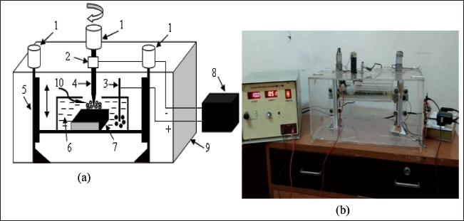
Studies examining the effects of varying concentrations of electrolyte on process responses have demonstrated that, up to a certain extent, higher concentrations generally result in higher MRR as well as Ra. These parameters may deteriorate as a result of decreased spark intensity after this ideal concentration. The method of drilling is powered by a controlled pulsing power source that delivers less current with significant voltage78–80. The drilling process for the workpiece relied on discharge energy, with an automatic feed system implemented. The tool electrodes are required to be submerged in the electrolytes by 2–3 mm in order for sparks to form. If a significant volume of gas containing hydrogen was collected on the tool’s surface, it was retracted. By monitoring the process’s behavior while employing exact tools to record current as well as voltage waveforms, the process was examined. The machining chamber’s fast spinning tool electrode was appropriately configured to regulate the workpiece’s movement until it made contact with tool and was firmly positioned 81 .
Results and discussion
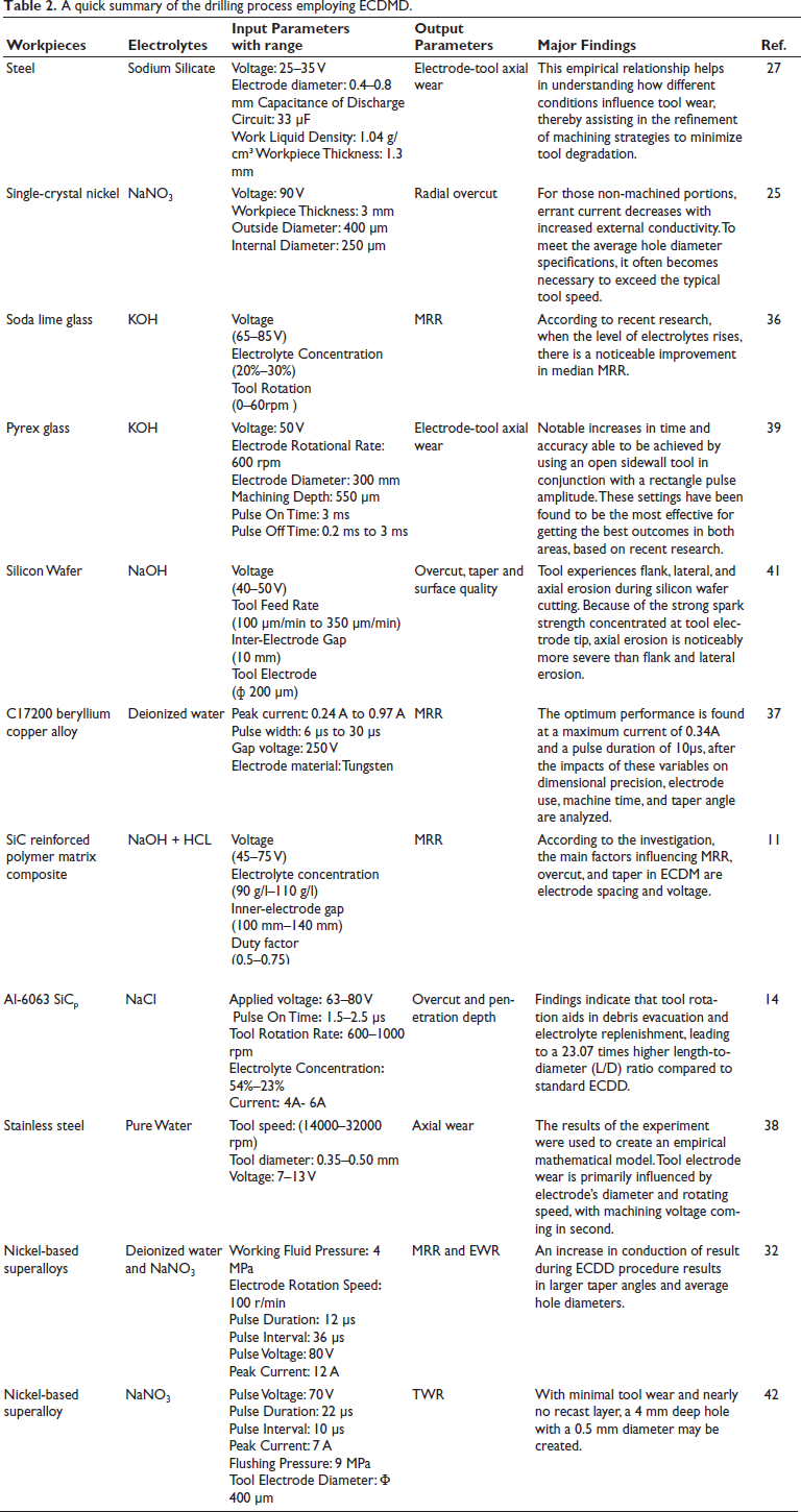
A thorough assessment of works divulges that several crucial input parameters, including current, voltage, electrolytic concentration, and component thickness, have a significant impact on key output responses during the drilling ECDM method with non-conductive materials, including TWR, overcut, MRR, and roughness of the surface (Ra). These variables and their resulting responses have intricate and non-linear interactions. Lower performance is typically the result of decreasing current, voltage, and pulse on time, while higher values typically lead to better output responses65. Moreover, there are notable impacts from work thickness and pulse off time, the variations of which are inversely correlated with the output responses. Additionally, whereas increased concentrations of electrolytes can initially increase output responses, they eventually cause a drop because they reduce electrolyte conductivity66. An overview of experimental observations from multiple investigations is shown in Table 2, which also includes details on electrolytes, process variables, output reactions, non-conductive sustainable materials, and key discoveries.
A quick summary of the drilling process employing ECDMD.
Research potential and scope for future work
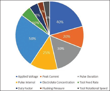
For improved dimensional precision and to create a symmetric pit on sustainably non-conductive materials, the ECDM drilling procedure is preferable. In addition, it makes sense to employ this procedure to make micro-holes in stiff, non-conductive, hard, sustainable materials which are too difficult to make with conventional techniques. The thickness of drilling handling material determined must have a diameter of 350–1,250 µm78. Permeability, as an outcome factor, indicates the possible path by which energy could enter a material. Overcut is a defining feature of the machining accuracy. In this correct modifying, selecting the minimal values is the best option. Aspect ratio, level of incision, and damage to the surface caused by drilling were all measured. The percentage of various input parameters have been used by several researchers in drilling ECDM in terms of 40% of applied voltage, 20% of peak current, 30% of pulse duration, 25% of pulse interval, 50% of electrolyte concentration, 10% of tool feed rate (TFR), 8% of duty factor, 5% of flushing pressure and 6% of tool rotational speed (TRS) is illustrated in Figure 4. Less effort has been made to consider the following procedure variables of drilling ECDM, such as TFR, duty factor, flushing pressure and TRS.
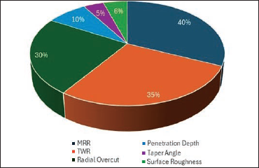
In addition, less trial work is carried out on penetration depth, surface roughness, and taper angle, followed by MRR, radial overcut, and TWR of the drilling ECDM procedure when cutting a variety of eco-friendly materials. As shown in Figure 5, the proportion of different output variables used in ECDM drilling is 40% of MRR, 35% of TWR, 30% of radial overcut, 10% of penetration depth, 5% of taper angle, and 6% of surface roughness, respectively. Therefore, more opportunities may be available to work on the following process characteristics such as penetration depth, surface roughness and taper angle.
Percentage of different input parameters of the drilling ECDM used by researchers.
Percentage of different output parameters of the drilling ECDM used by researchers.
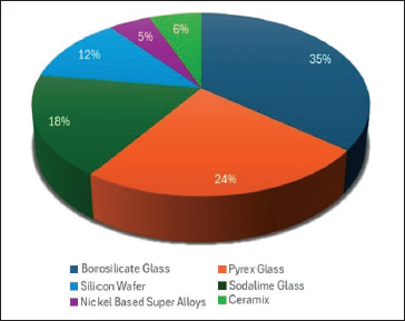
ECDMD is playing a challenging role in manufacturing various intricate shapes using sustainable materials in modern industries. The previous literature has been utilized in different experimental and theoretical works using the following sustainable materials, such as 35% in borosilicate glass, 24% in Pyrex glass, 18% in sodalime glass, 12% in silicon wafer, 5% in nickel-based super alloys, and 6% in ceramics. Because silicon wafer, nickel-based super alloys and ceramics are more suitable for drilling ECDM than glass fiber–reinforced composite, more opportunities are available for machining of ceramics and silicon wafer in the ECDMD process, as shown in Figure 6.
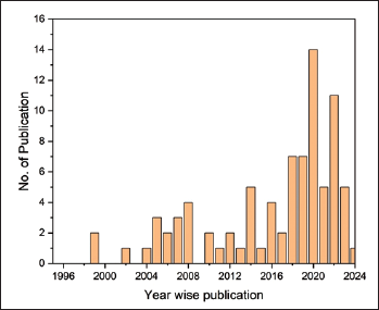
The literature review has been considered from 1996 to 2024 in the present work and segregated the trend of year-wise publications from approximately 1% to 17%, respectively. Very few publications on the topic of the drilling ECDM technique for machining sustainable materials were published in 2024. Figure 7 shows the trend of the graph, which focuses on the publication rate year over year. Therefore, there is greater room for the drilling ECDM process to begin in order to create a hole in sustainable materials that are electrically non-conductive.
Percentage of publications on sustainable materials.
Number of publications year-wise.
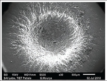
The set of diagrams from Figures 4 to 7, which illustrate the works of different authors, is an attempt to investigate exploratory trends in the drilling-ECDM process in terms of input parameters, output parameters, sustainable materials, and publishing years. By altering different electrolytes using different mixtures of optimization tools, the investigation could be extended in the future to encompass multiple combinations of non-conductive, sustainable materials. Moreover, the symmetrical hole and surface morphology of the machined borosilicate glass workpiece during the ECDD process are shown in Figure 8 using a scanning electron microscope (SEM). The experimental parameters, including applied voltage = 70 V, current = 2 A, inter-electrode spacing = 40 mm, electrolyte concentration = 300 g/L, and rotating electrode speed = 300 rpm, are considered 47. However, higher voltage and current resulted in an uneven drilling surface with some significant pits, recast zones, microcracks, and converted layers. The artwork can also be extended through the use of different experimental configurations; a critical literature review serves as the sole basis for addressing the following research gaps. The drilling ECDM process line diagram previously mentioned indicates that this is a very favorable technique for machining sustainable materials that are electrically non-conductive in automotive industries. This process was also widely used for creating holes in sustainable, non-conductive materials such as glasses, composites, soda lime, and silicon wafer. These materials are very relevant outside of the automobile, aerospace, and military sectors, among other fields.
Machined borosilicate glass workpiece during the ECDD process using SEM 47.
Conclusions
This article reviews several research papers that studied the drilling concerns of electrically non-conductive sustainable workpieces using the ECDMD process. In conclusion, we make the following abridged statements:
For industries where electrically non-conductive sustainable materials are being drilled, the most effective, suitable, and feasible drilling method is ECDMD. Studies in this particular area have been undertaken after 2005, according to published literature that is now accessible. According to the research, less effort has been made on procedure parameters of drilling ECDM such as TFR, duty factor, flushing pressure, and TRS, with percentages of 10%, 8%, 5%, and 6%, respectively. Research demonstrated that less practical effort has been on the penetration depth of 10%, surface roughness of 6% and taper angle of 5%, followed by MRR of 40%, radial overcut of 35%, and TWR of 30% in ECDM drilling procedure when many sustainable materials are being machined. Based on a meta-analysis, most work was done on sustainable materials that are electrically non-conductive, such as 35% borosilicate glass, 24% Pyrex glass, and 18% soda-lime glass. Moreover, the least amount of work was done on 12% silicon wafer, 5% nickel-based super alloys, and 6% ceramics. The year-wise publications of the research trend have been examined from 1996 to 2024, and a few research papers were found in 2024.
A decreased effort has been put ahead by investigators to address issues like retrieving debris particles after machining and recycling electrolyte. But there is still more to be done in these areas. Drilling an opening within terracotta with a beneficial electrode arrangement is validated by applying an intrusive tool with a spinning motion to create further electrical current that accelerates the machining process. The removal of sustainable materials, which are electrically non-conductive, turns them more durable through these procedures, as a result, the quality generated has risen globally. However, higher voltage, electrolyte concentration, and current resulted in an uneven drilling surface with some significant pits, recast zones, microcracks, and converted layers. To reduce these kinds of surface textures, proper optimization settings must be selected.
Footnotes
Declaration of Conflicting Interests
The authors declared no potential conflicts of interest with respect to the research, authorship, and/or publication of this article.
Funding
The authors received no financial support for the research, authorship, and/or publication of this article.