
Abstract
Microfluidic systems play a pivotal role in various fields, including biotechnology and chemistry, due to their ability to efficiently mix small volumes of fluids. Achieving rapid and precise mixing is essential for applications such as chemical reactions and diagnostics. These microfluidic systems need to efficiently mix different substances at the microliter or nanoliter scale. The importance of microfluidic mixing lies in its applications across various fields, including chemical analysis, drug development, biology, and diagnostics. In this study, an attempt has been made to study the mixing performance of rectangular, trapezoidal, semi-circular, and triangular or V-shaped channels at a fluid velocity of 0.01 m/s and to identify which cross-section among them exhibits the best mixing, followed by the fabrication of microchannels using a laser on polymethyl methacrylate (PMMA). The models were analyzed using ANSYS, and studied turbulence kinetic energy, velocity streamlines, and mixing time. The mixing efficiency of semi-circular, rectangular, trapezoidal, and triangular channels was 81.43%, 70.26%, 90.52%, and 93.5%, respectively. Triangular microchannels have exhibited better mixing performance than the other designs. The triangular cross-section microchannels were fabricated using a CO2 laser on PMMA, and their surface morphological studies, such as scanning electron microscopy (SEM), contact angle, and mechanical probe scanning for channel profile, were carried out.
Introduction
The origins of microfluidics can be traced back to the mid-20th century when micro-fabrication techniques began to gain prominence. The pioneering work of Kuhlman and Van Atta in the early 1960s marked the nascent exploration of small-scale fluidic systems. Many researchers have extensively investigated flow in narrow tubes over the years. Schlichting 1 compiled theories and experimental findings, covering pioneering studies from Hagen 2 and Poiseuille 3 up to 1979. Subsequently, during the 1980s, the intersection of microfabrication technologies with fluid dynamics principles gave birth to the modern field of microfluidics. The advent of computer-aided design (CAD) tools and precision micromachining methods has empowered researchers to craft intricate microchannels and manipulate fluids at unprecedented scales. This marriage of microengineering and fluid dynamics laid the foundation for the exploration of microfluidics.
Microfluidics, the study of how fluids behave at micro- or nano-scales, has sparked big changes in areas like biotechnology and life sciences, predominantly. This is because it lets us control fluids very precisely in very small volumes. But there is a challenge as to how to mix tiny particles efficiently in these small volumes. In typical water-based microfluidic systems, with a channel width of 100 µm, the flow inside microfluidic channels is primarily characterized by laminar behavior, and the Reynolds number typically falls within the range of about 0.1–100. 4 Mixing two miscible liquids cannot result in a uniform blend by merely allowing them to flow together in a straight path. Typically, these fluids exhibit pronounced concentration gradients along the direction of flow. 5 The blending of two fluids through axial convection is most efficient at elevated Peclet numbers, while radial diffusion is most pronounced at lower Peclet numbers, a phenomenon often referred to as Taylor’s dispersion. 6 There is a considerable pressure drop in the microchannels due to high frictional losses. 7
This affects the process of mixing two miscible liquids, as seen in testing of medicine, chemistry, and biology, including processes like making chemicals and delivering drugs. They are good because they use small samples, mix things fast, make reactions happen quickly, and even create complex patterns of mixing. 8 Normal mixing methods, which depend on media flowing slowly, do not work well on such tiny scales. Researchers are working on new ideas to provide effective mixing using both passive and active mixers.9, 10
A lot of research has been done on the cross-sectional shape of the microchannels and their heat transfer capabilities and separation, but little has been done with respect to the diffusional mixing of two liquids flowing in straight channels of different cross-sections. Guan et al. have reported on effect of cross-section with respect to particle separation performance, 11 Harirchian and Garimella have reported on the effect of cross-sectional area with respect to heat transfer, 12 Clark et al. have reported about the mixing performance in serpentine microchannels, 13 Sudarsan and Ugaz have studied on fluid mixing on planar spiral microchannels, 14 Hsiao et al. have studied fluid mixing in microchannels with longitudinal vortex generators, 15 Stroock et al. have reported on chaotic mixing on microchannels, 16 and pointed out the difficulty in the fabrication of staggered microchannels. Kashid et al. have worked with five different cross-sections, including square, rectangular, trapezoidal, concentric circular channels, and caterpillar-inspired microchannels, but with non-uniform mixers. 17 Liu et al. have reported on mixing with a square-wave mixer, a three-dimensional serpentine mixer, and a staggered herringbone mixer. 18 Kockmann et al. have studied trapezoidal and rectangular cross-sections for passive mixing performance, 19 but there are very few to none who have reported on the diffusive mixing abilities of microchannels purely due to their cross-sectional shapes. The cross-sectional shape of the microchannel is crucial in determining the efficiency of microchannel heat sinks, as it significantly influences the heat transfer and flow behavior of the cooling medium. 20 Battaglia et al. have studied the mixing behavior on two geometries, that is, square and circular microchannels, 21 where the latter has demonstrated better mixing performance and reduced mixing time at the same Reynolds number flow.
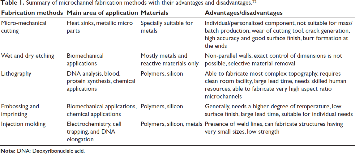
Afzal et al. 22 have reviewed various fabrication processes such as micro milling, wet and dry etching, lithography, embossing, and others, and listed out their advantages and disadvantages, they have also listed out the various laser-based fabrication methods, such as ultraviolet (UV) laser, infrared (IR) laser, pulsed lasers, and provided information about their application, suitable material, and their advantages and disadvantages, this helps with the identification of the most suitable fabrication method, with an intention to support the research community to select the suitable channel design and fabrication process, as shown in Table 1.
Summary of microchannel fabrication methods with their advantages and disadvantages. 22
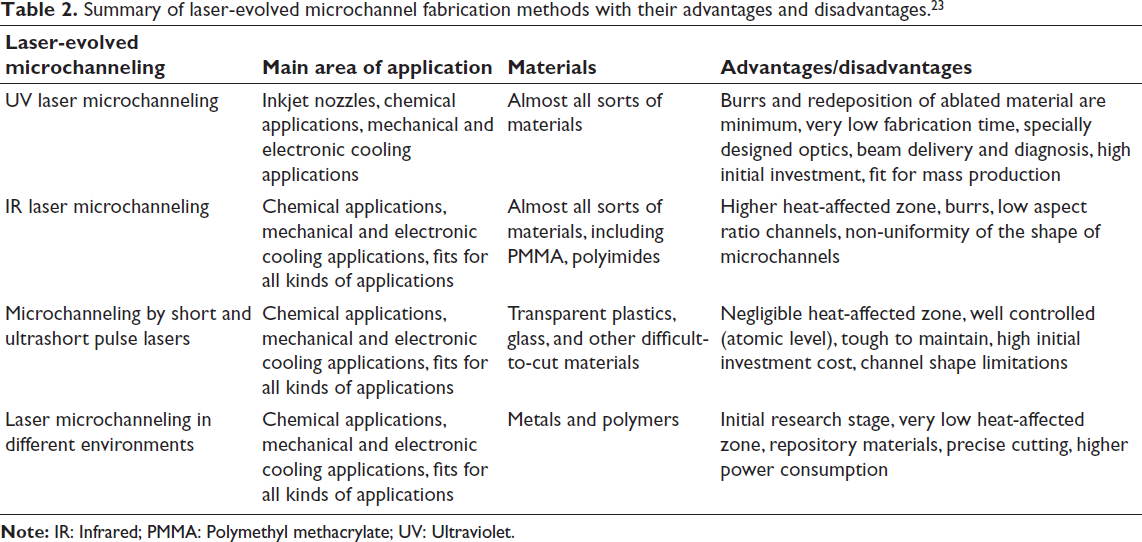
Srikantaprasad and Tom Mathew 23 have provided a comprehensive review on the fabrication of microchannels for microfluidic devices using different lasers, along with the achievable roughness, minimum feature size, resolution/feature tolerance, accuracy/positional tolerance, aspect ratio, and structural dimension, as shown in Tables 2 and 3.
Summary of laser-evolved microchannel fabrication methods with their advantages and disadvantages. 23
Comparison of master fabrication technologies. 23
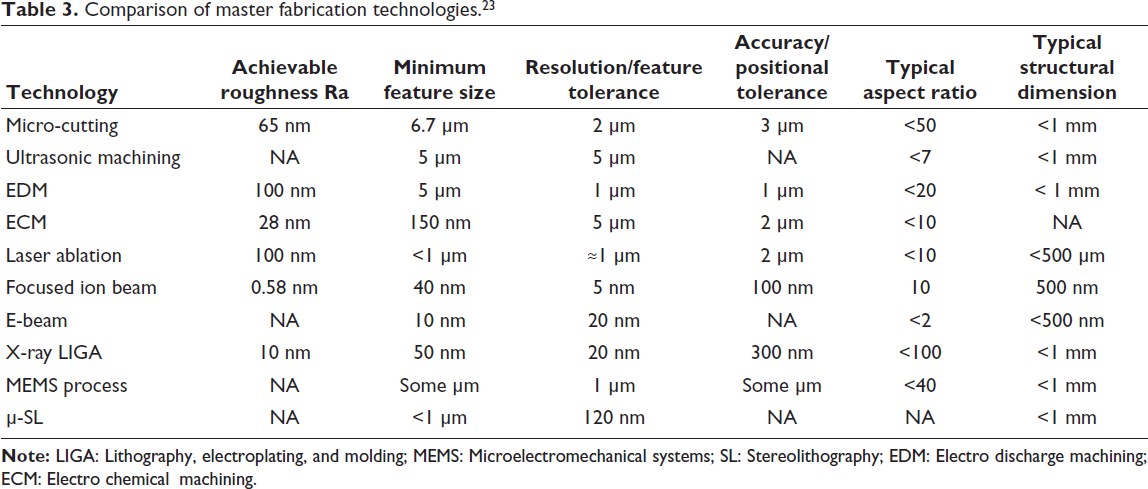
Among the different types of micromanufacturing methods reviewed by Srikantaprasad and Tom Mathew, 23 such as micro milling, ultrasonic machining, micro stereolithography, and others, laser ablation seems to be ideal for prototyping of microfluidic channels, on a wide variety of materials, including polymers. CO2 laser is effective for deep, tunable polymethyl methacrylate (PMMA) channels. 24 Chen et al. 25 reported that the CO2 laser is reliable for repeatable microfluidic channel production in PMMA.
In this study, PMMA was chosen as the substrate due to its inherent properties of being transparent, bio-compatible, 26 low cost, easy availability, maintains channel geometry well, 27 resistant to many aqueous solutions and weak acids/bases, suitable for a variety of biological and chemical assays, and its surface can be modified to suit the application using coatings and plasma treatment.28, 29
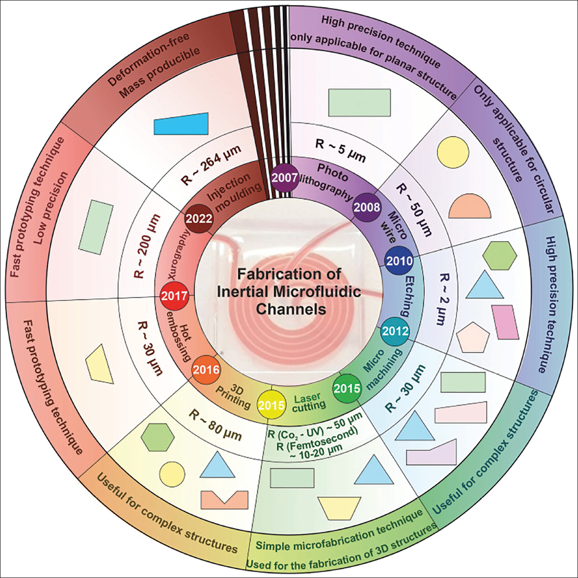
Akbari et al. 30 have reviewed and provided a comprehensive list of different fabrication methods, especially indicating the microchannel cross-section geometries that can be fabricated with the respective fabrication methods, their resultant surface roughness, and their applications are depicted in Figure 1.
Schematic of microfluidic fabrication methods. 30
In this research, an attempt has been made to study the mixing behavior of various microchannel shapes; they include the semi-circular, trapezoidal, rectangular, and V-shaped channels. These shapes were deliberately selected because they introduce different modes of fluid motion. The different modes of fluid motion are based on time-dependent (steady, unsteady), compressibility, viscosity, flow characteristics (laminar, turbulent), and flow path (rotational, non-rotational). These distinct shapes were chosen for study since they are easier to fabricate and are chosen by many researchers and utilized in the study of their passive mixers, such as micro tesla valves, staggered herringbone, serpentine, microchannels, and others. The cross-section that exhibits the best mixing performance among them will be fabricated using a CO2 laser on a PMMA substrate, and its surface morphology using scanning electron microscopy (SEM) images, contact angle measurements, mechanical probe-based profile mapping, and measurements.
Methodology
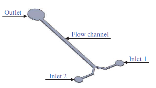
In this study, the microfluidic channels with different cross-sections were designed, such as semi-circular, trapezoidal, rectangular, and V-shaped channels, and conducted a simulation of the channels as a well-defined basic sharp-edged geometry, as shown in Figure 2. The volume of all the designs was kept constant in order to get accurate results when compared between different designs. This is done by keeping the surface area and the striation length the same, but changing the channel width. The volume of the channels was designed to be at 0.5 mm3, with a variation of ±400 µm3 across all geometries. The length of the channel was constant at 5 mm.
3D model of microfluidic mixture.
Modeling of microfluidic channels with different cross-sections
The channels have been modeled using the SOLIDWORKS 2020 CAD tool, with various designs having variations in the cross-section. The length of all the designs was 5,000 µm or 5 mm. The inlet reservoirs of both fluids, that is, inlet A and inlet B, were designed to be Ø250 µm, and the outlet reservoir was Ø500 µm. The typical Y-type mixer was used for all the designs, and the angle at the converging section was kept constant at 90° for all designs (refer to Figures 2 and 3).
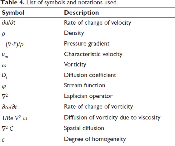
The list of symbols and notations are provided in the Table 4.
List of symbols and notations used.
Analytical modeling
The equations used for analysis are as follows:
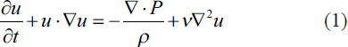
The Navier–Stokes equation, The Navier–Stokes equation describes how the velocity of a fluid evolves over time due to forces like pressure, viscosity, and external influences.
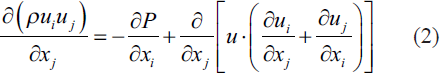
Where ∂u/∂t represents the time rate of change of velocity, The conservation of momentum equation, The conservation of momentum equation states that the rate of change of momentum in a fluid is equal to the sum of external forces acting on it.
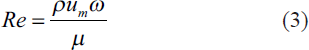
Where ρ is the density of the fluid, Reynolds number (Re) The Reynolds number is a dimensionless quantity used in fluid mechanics to determine the flow regime, laminar or turbulent flow, of a fluid.
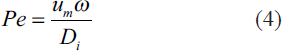
Where ρ is the fluid density (1,000 kg/m3), is the characteristic velocity of the fluid, is the characteristic length, and is the dynamic viscosity of the fluid. Peclet number (Pe) The Pe number is commonly used to characterize the relative importance of convection to diffusion in a particular flow system. The Peclet number (Pe) is given by,
where
Stream function equation
The stream function equation defines a scalar function whose contours represent streamlines, ensuring continuity in incompressible 2D flow.
Where φ is the stream function,
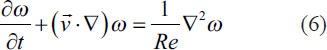
Vorticity transport function equation
The vorticity transport function equation is used to define the distribution of fluid fields in a microchannel.
Where ∂ω/∂t is the rate of change of vorticity with respect to time, this term accounts for how vorticity evolves over time,
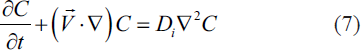
Convection—diffusion equation
The convection-diffusion equation is commonly used to describe the transport of a conserved quantity, typically concentration (C), in a fluid flow, including microfluids. The equation is given by,
where
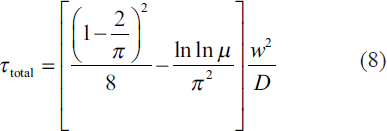
Mixing time equation
The mixing time equation is used to calculate the total mixing time ( Where
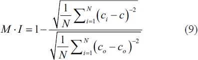
Mixing efficiency calculation
The mixing efficiency equation is used to calculate the mixing efficiency for a mixing process.
Where M⋅I represents the mixing efficiency, N is the number of data points or measurements,
Fourier number
This Fourier number is used to determine the length of the microfluidic channel for a Y-type micromixer.

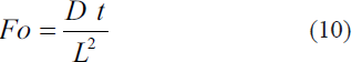
Where, Fo is the Fourier number (dimensionless number).
D is the coefficient of diffusivity (m2/s); t is the mixing time (s); L is the length of the channel (m); Fo to be 0.5; the diffusion coefficient for water at 325 K is 3.0 × 10⁻⁹ m2/s, and at 275 K is 1.1 × 10⁻⁹ m2/s.
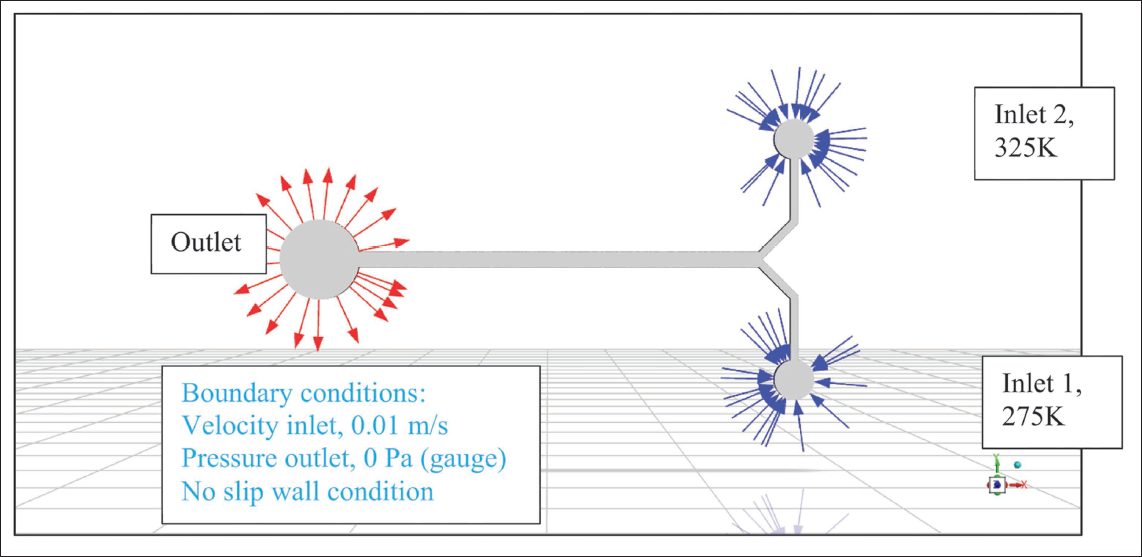
A Y-type mixer with a bifurcation angle of 90° was used for the study. Water was chosen as the medium for mixing, and to examine the mixing behavior, with inlet 1 supplied at 325 K and inlet 2 at 275 K to observe the mixing behavior as shown in Figure 2. The dimensions of the inlet reservoirs, bifurcation angle, channel width, channel length, and outlet reservoir are provided in Figure 3.
Channel dimensions of the microfluidic mixer.
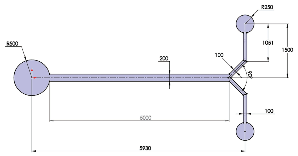
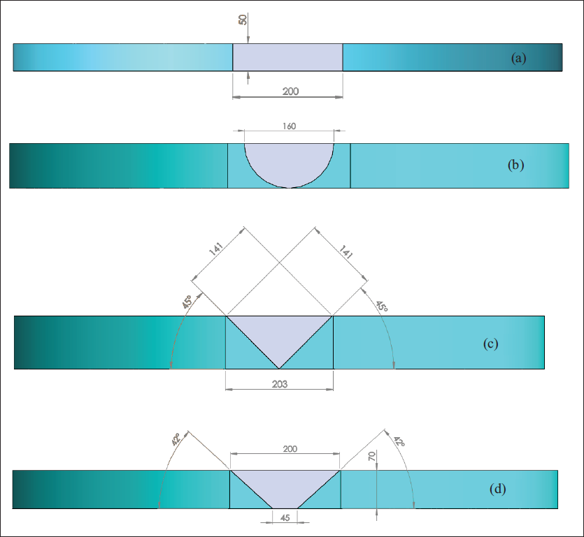
In the rectangle, V-shaped/triangular, and trapezoidal cross-section, the width of 200 µm is common, but the depth, angle, and the bottom width for trapezoidal and triangular section channels are designed such that the volume for all the channels, irrespective of the cross-section geometry, is uniform. For semi-circle cross-section, the width is 160 µm, and this forms the depth as well. The volume of 0.5 mm3 was maintained constant across all geometries. The cross-section dimensions of various geometries, such as rectangle, semi-circle, triangular, and trapezoidal, are shown in Figure 4.
(a) Rectangular cross-section, (b) semi-circular cross-section, (c) V-shaped cross-section, and (d) trapezoidal cross-section of the microfluidic channels.
Regarding spatial discretization, different methods were selected: the least-squares cell-based method for gradient calculations, the pressure staggering option (PRESTO) method for pressure, the first-order upwind method for volume fraction, and the second-order upwind method for momentum. The inlet boundary condition was specified as a velocity-inlet with a flow velocity of 0.01 m/s, with the inlet velocity determined by the nanofluids flow rate. The outlet boundary condition was set to pressure-outlet with a pressure of 0 Pa, and a no-slip wall condition was applied to the remaining walls, as shown in Figure 5.
Boundary conditions are applied to the micromixer geometry.
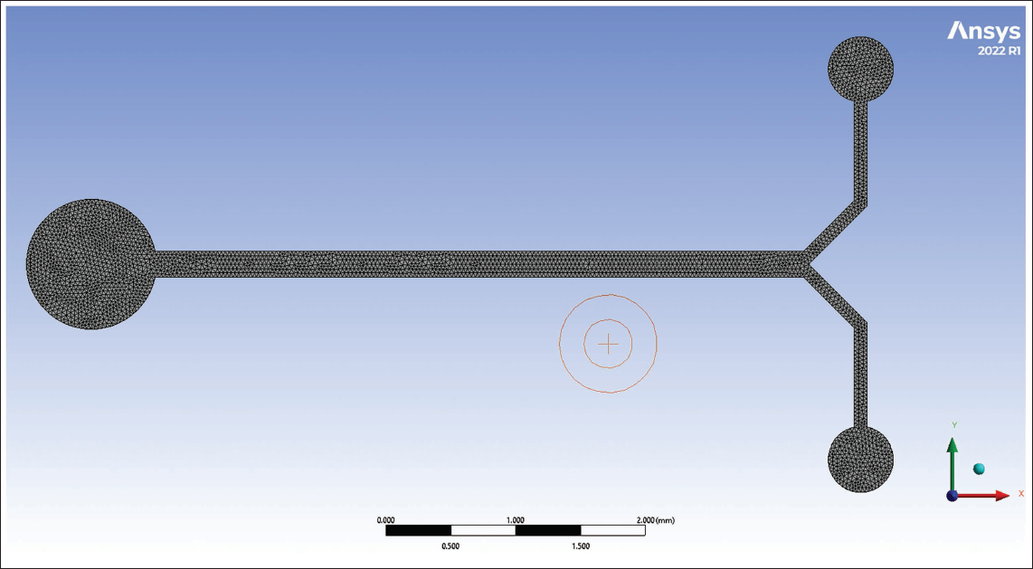
In this study, a tetrahedral mesh was used to discretize the micromixer geometry, enabling accurate representation of complex 3D features as shown in Figure 6. A global body sizing of 0.01 mm was applied to ensure uniform element distribution across the domain, and critical regions such as inlets, outlets, and mixing interfaces were locally refined to a mesh size of 1 µm to capture detailed flow behavior.
Meshing of the fluid element with a tetrahedron mesh and body size meshing.
Results and discussion
Flow analysis in microchannels
Mixing within the microfluidic channels is influenced by two primary factors: (a) the duration that fluids stay within the microchannel, and (b) the chaotic fluid motion generated within the microchannels because of their specific geometry. 16 Turbulence kinetic energy (often denoted as k) represents the energy associated with the turbulent motion of fluid particles within a flow field. Turbulence kinetic energy provides information about the intensity of turbulent fluctuations in a fluid, which is essential for understanding and analyzing turbulent flow behavior. It is a measure of the energy contained in the turbulent eddies or fluctuations within the flow, and it is calculated as a function of the velocity components and their fluctuations.
The equation for turbulence kinetic energy (k) can be expressed as:

k is the turbulence kinetic energy.
u′, v′, and w′ are the velocity fluctuations in the x, y, and z directions, respectively.
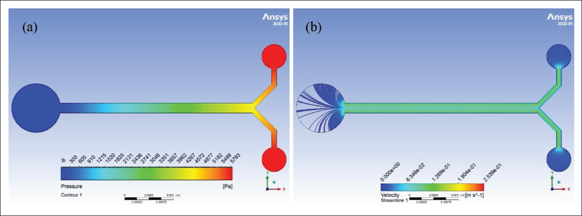
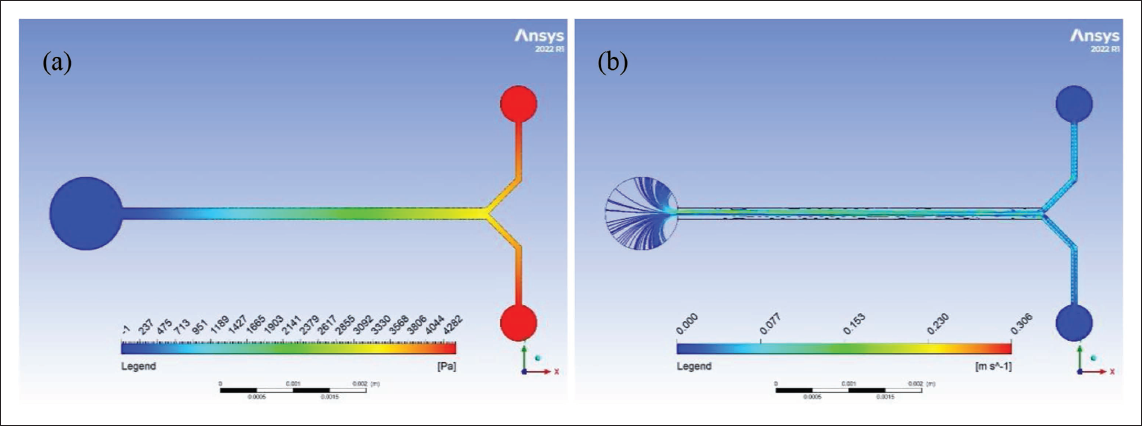
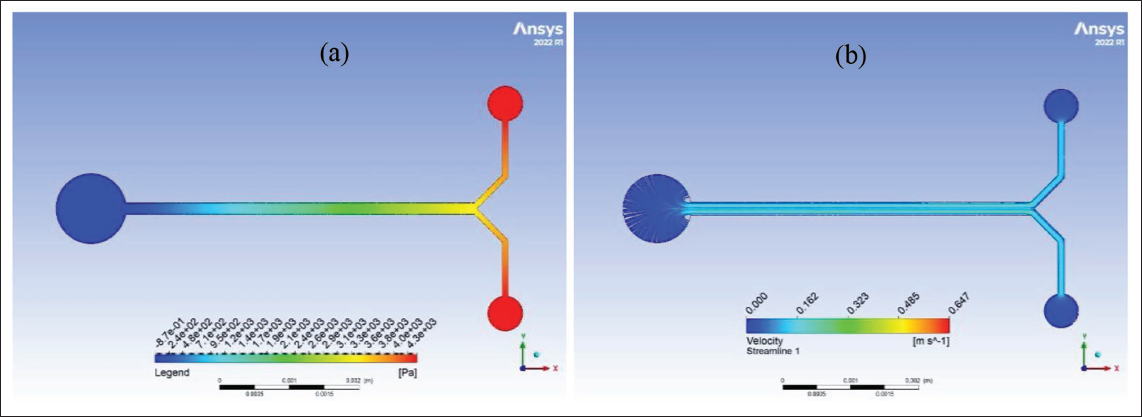
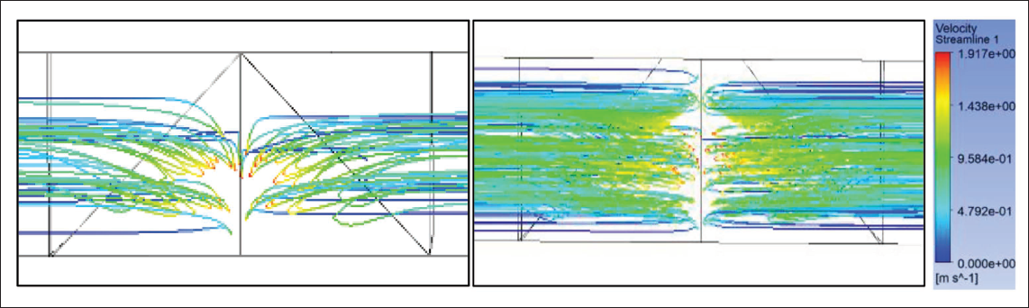
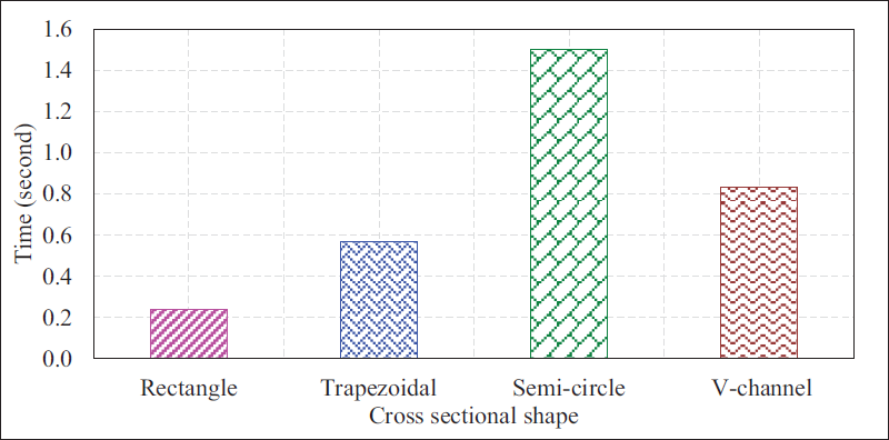
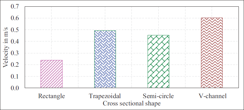
Figures 7–10 depict the pressure gradients and velocity streamlines for rectangular, semi-circular, triangular, and trapezoidal cross-sections as a result of two liquids flowing through the channels under the predefined boundary conditions. Smooth, symmetric streamlines indicate uniform laminar flow, whereas swirling or looped streamlines indicate vortex formation as shown in Figure 11, secondary flows that enhance mixing. Sections of uniform velocity are shown in the figures with a constant color, whereas sections in the channel where different hues are visible show that there is a presence of variation in the velocity. In triangular cross-section channels, velocity variation occurs due to the no-slip condition at the walls and the influence of the sharp corners. These geometric constraints result in a non-uniform velocity field, with maximum flow velocities concentrated along the central region of the cross-section and significantly reduced velocities near the triangle vertices. This irregularity helps in mixing as it disturbs the laminar flow regime. Figures 12 and 13 show the mixing time and maximum velocity across the various cross sections. Table 5 shows the maximum velocity, maximum turbulence intensity and mixing time for the various cross sections.
(a) Pressure and (b) velocity streamlines for rectangular cross-section.
(a) Pressure and (b) velocity streamlines for semi-circular cross-section.
(a) Pressure and (b) velocity streamlines for triangular/V-shape cross-section.
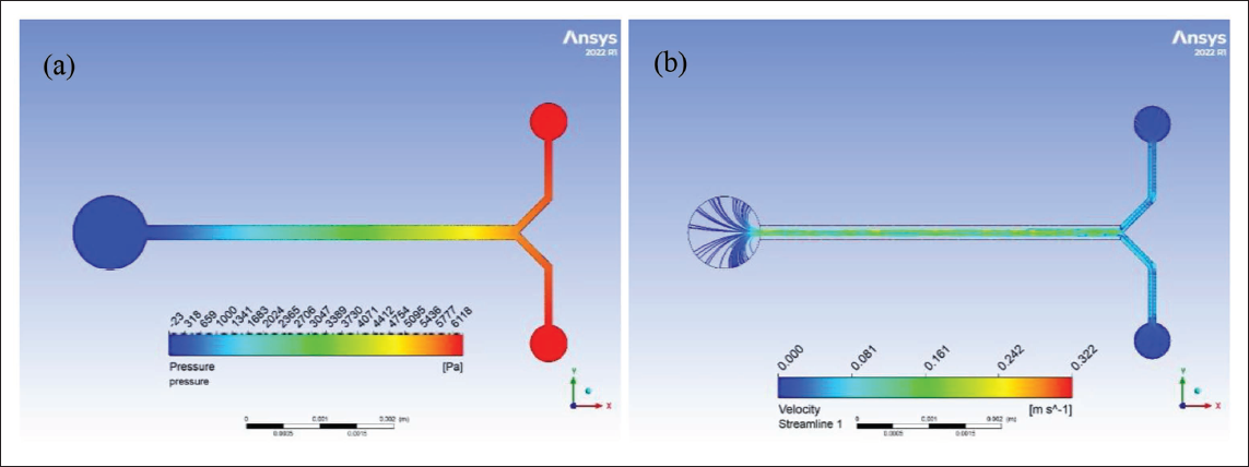
(a) Pressure and (b) velocity streamlines for trapezoidal cross-section.
Cross-sectional view of the triangular channel and the trapezoidal channel for viewing the vortices.
Mixing time required for different channel shapes.
Maximum velocity of different channel shapes.
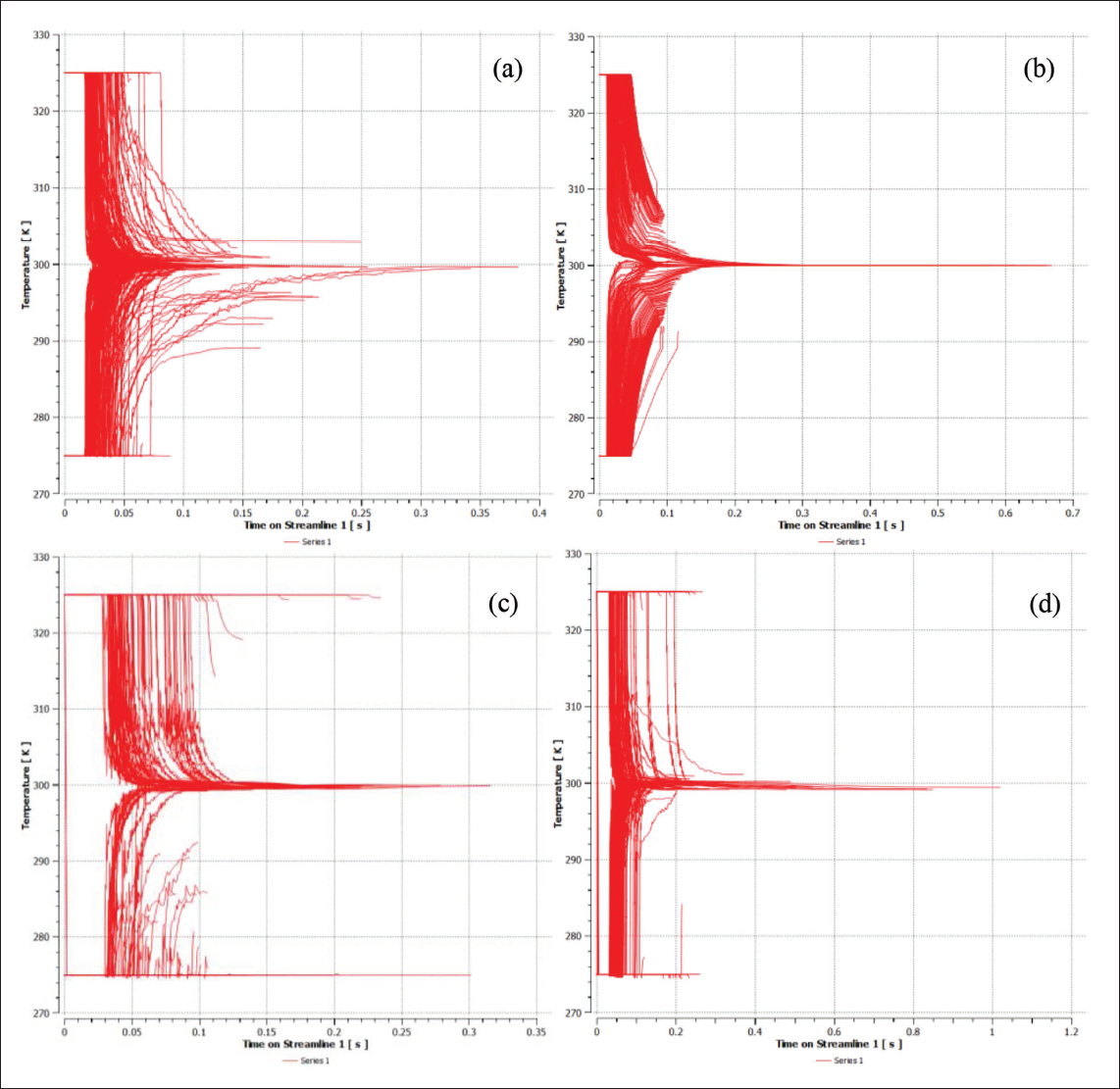
Variation of temperature with respect to time for the (a) rectangular, (b) triangular, (c) trapezoidal, and (d) semi-circular.
Results obtained for different shapes of channels.
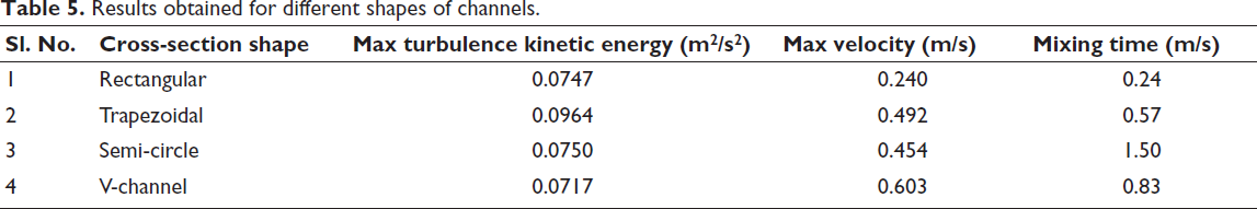
The higher turbulence intensity is exhibited by the trapezoidal cross-section, next only to the semi-circular cross-section. The higher velocities are achieved in V channels because they have a narrower cross-sectional area compared to other channel shapes, such as rectangular or cylindrical channels. V-channels achieve rapid mixing due to chaotic advection and are particularly effective in inducing secondary flows for improved mixing. 31 Also, V-channels generate longitudinal and transverse vortices, reinforcing near-wall mixing without drastically increasing friction. 32 The geometry reduces flow resistance, minimizing the impact of wall friction on the flow velocity, and allowing the fluid to flow more freely and at a higher speed. Also, the converging walls of the V-shape can induce chaotic advection and turbulence, leading to increased flow velocity in some regions. The variation of temperature along the channel over time for all the 4 cross sections have been shown in Figure 14.
Fabrication of microchannels
Based on the above results, it can be concluded that the triangular cross-sections have better mixing performance. The literature suggests that the triangular cross-sections are formed using the carbon dioxide laser on PMMA. The formation of V-shaped channels is due to the laser beam having the distribution of energy resembling as a Gaussian curve, 33 with the highest energy at the center of the beam and reducing towards the circumference or edges of the beam, this is the reason, the channels are deeper at the center and the depth decreases away from the center, thereby resembling the V-shaped or triangular cross-section of the microchannels fabricated.
Schematic representation of laser-material interaction.
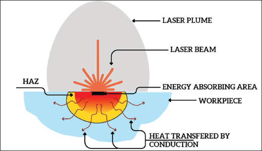
In pulsed lasers, there is localized material removal with a minimal heat-affected zone. Here, the material is removed by direct ablation, so there is an occurrence of a channel whose shape is a transition between triangular and rectangular/square, which is trapezoidal. Laser beams are also treated with a homogenizer to convert them into a top-hat beam, with a much uniform energy distribution across, this also enables to get squarer channels. The schematic representation of laser-material interaction is shown in Figure 15.
Surface morphological study of microfluidic channel
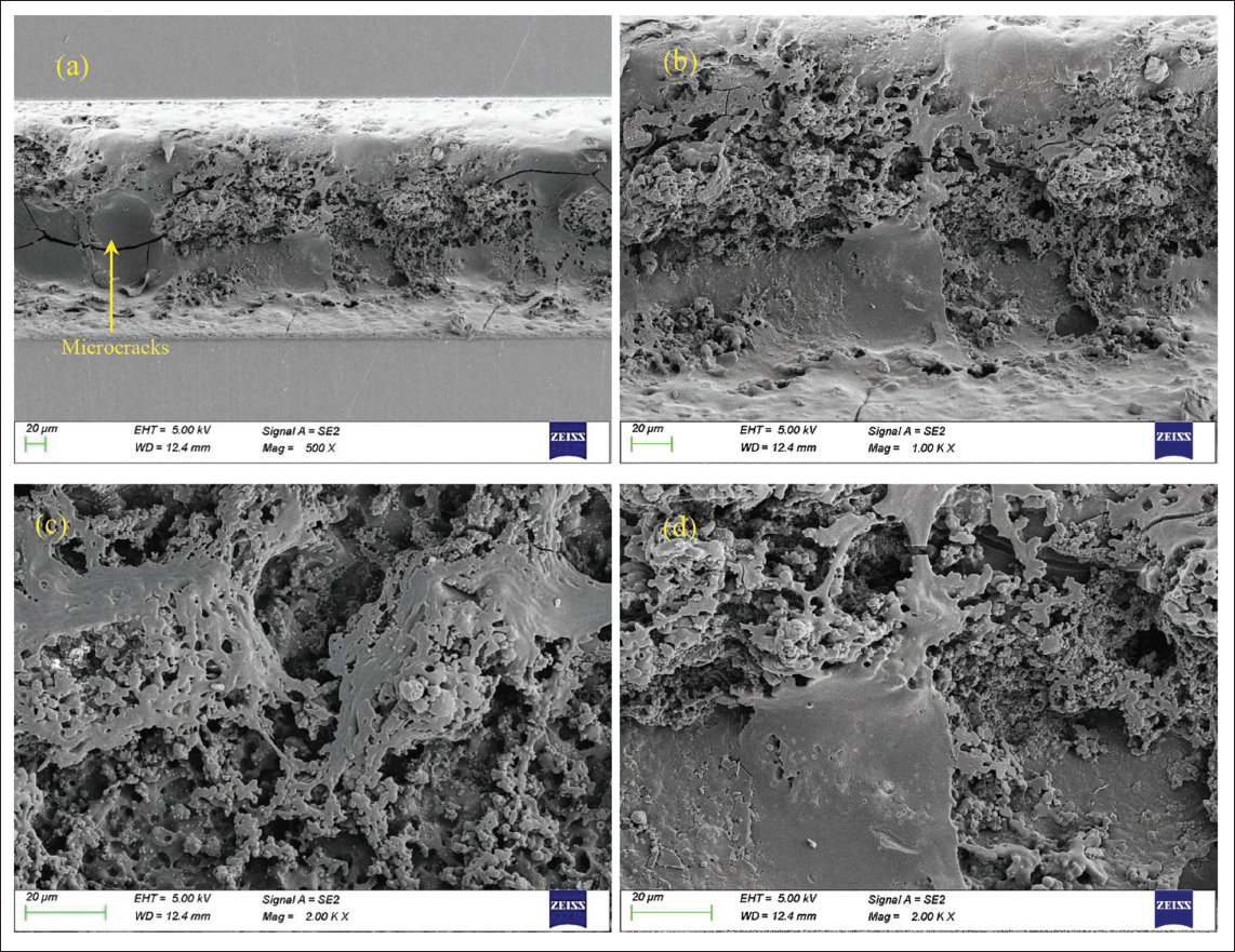
The surface of the channel reveals a complex landscape characterized by numerous peaks and valleys. This textured surface is primarily the result of the uneven ablation of PMMA, especially evident along the microchannel surfaces. The presence of these peaks and valleys significantly contributes to the roughness of the channels, affecting their physical characteristics. Furthermore, upon closer examination, we can identify certain regions where micropillar-like structures have formed. These distinct formations not only add to the surface roughness but also play a crucial role in enhancing the hydrophobic nature of the surfaces. Consequently, the combined effect of the roughness and micropillars leads to increased surface hydrophobicity, which has important implications for the channel’s functional properties, such as the flowability of liquids through them, the surface area is increased due to the micropillars formed, and the turbulence intensity of liquids flowing through them is higher than with smoother channels, aiding in the mixing of two liquids as shown in Figure 16.
Surface morphological imaging at (a) 500X, (b) 1kX, (c) 2kX, and (d) 2kX of the channels manufactured using a CO2 laser on polymethyl methacrylate (PMMA) samples.
Surface profile characterization and analysis of microfluidic channel
The cross-sectional profile of the channel was examined in detail using a stylus probe (DektakXT 150). Stylus profilometers are precision instruments that use a finely-tipped probe to physically trace along a surface, enabling the detection of variations in surface height. As the probe moves mechanically across the surface, it continuously records height data, which is crucial for generating an accurate surface profile. This measurement process is controlled by a feedback loop that carefully monitors the force exerted by the sample as it pushes against the probe, ensuring precise readings as it scans along the channel’s surface. This method provides a highly detailed visualization of the channel’s topography, capturing subtle features that define the surface profile.
Surface profile analysis with a mechanical probe on channels fabricated using a CO2 laser on polymethyl methacrylate (PMMA); V-shaped.
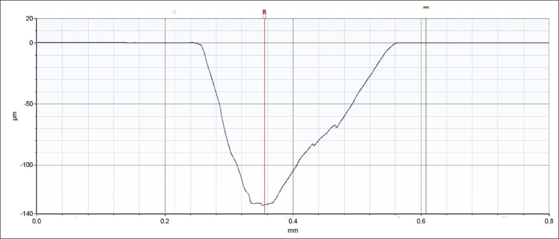
It can be seen from the images that we have an example of a trapezoidal cross-section channel obtained, and a V-shaped cross-section channel in the other. The resultant sections are due to the laser energy, laser frequency, and scan speed. Usually, high laser energy tends to form V-shaped channels due to a high ablation rate and the Gaussian profile of the laser energy distribution across the laser beam. We get similar results with low scan speeds, due to the high energy available at the substrate at a given time, which induces more ablation and deeper channels as shown in Figure 17.
Surface wettability study of microchannels
A KRÜSS DSA25E drop-shape analyzer was utilized to perform contact angle measurements, specifically to determine the angle of water droplets on both the as-cast PMMA surface and the laser-machined surfaces of the microchannels. The contact angle is defined as the angle created at the three-phase boundary where a solid surface, a liquid droplet, and the surrounding air (or an alternative gas) intersect. This angle measurement is crucial for evaluating wettability, as it indicates the surface’s tendency to repel or attract water. By analyzing the contact angle, we can gain insights into the surface characteristics, helping us determine if it behaves in a hydrophobic (water-repelling) or hydrophilic (water-attracting) manner. The samples were rinsed with distilled water, and any excess water was removed using a blow-dryer. Purified distilled water was used as the fluid droplet for the measurements.
Contact angle measurements on (a) as-cast polymethyl methacrylate (PMMA)—hydrophilic surface; (b) CO2 laser machine surface on PMMA—hydrophobic surface.
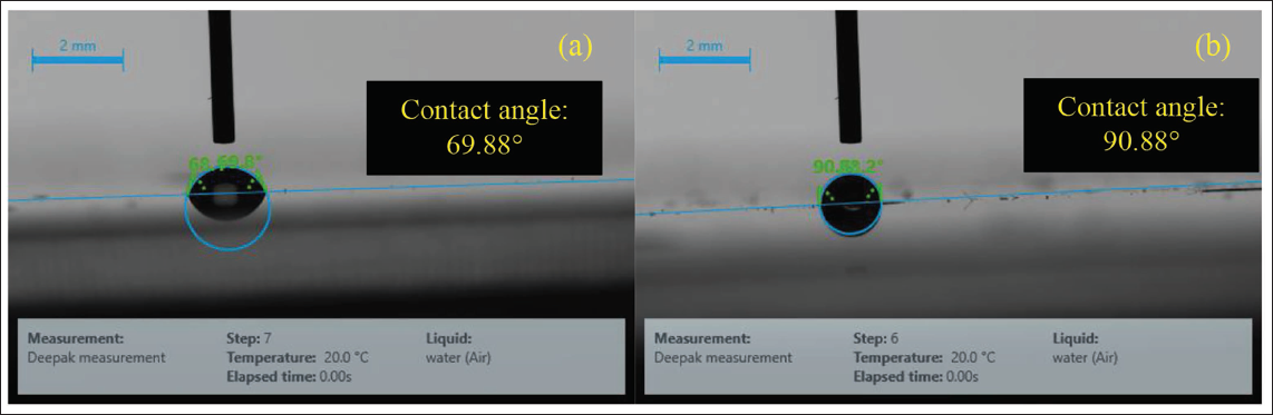
The water droplet on the sample surface was captured and analyzed to determine the contact angle. This angle is defined as the angle between the tangent to the droplet’s surface at the three-phase boundary—where the solid, liquid, and air meet—and the solid surface itself. To ensure accuracy and consistency, contact angle measurements were taken at five different locations on each sample type, helping to eliminate anomalies and confirm repeatability in the results. The contact angle of water on the as-cast PMMA sheets was measured at 69.88°, while the angle in the microchannels was 90.88°. This increase indicates that laser micromachining has introduced a hydrophobic effect within the channels, which supports smoother liquid flow along these surfaces as shown in Figure 18.
To restore or retain the original hydrophilic properties, post-processing treatments can be applied. Maxim et al. 34 have remarked that there is no need for additional coating. Whereas Kahraman et al. have experimented on fluorinated silane coatings on PMMA and remarked that they show long-term stability in retaining hydrophobicity in microfluidic channels.34, 35 Storage in desiccators and argon chambers introduces polar functional groups, thereby improving hydrophobicity. 36
Conclusion
The microfluidic channels with different cross-sectional shapes were studied for their mixing behavior while maintaining a constant volume across all designs. The trapezoidal and V-shaped cross-sections exhibited excellent mixing performance compared to the other shapes, owing to the high turbulence kinetic energies at 0.1 and 0.07 m2/s2, respectively, and high flow velocities. It can also be observed that 100% mixing is obtained in V-shaped channels, compared to the other channel designs. An in-depth analysis of the surface morphology, profile of the cross-section, and wettability studies has been carried out to further strengthen the statements as to why laser manufacturing of microfluidic channels is favorable. This is to help the researchers as a guide to choose the optimum channel cross-section shape and the fabrication method for microfluidic channels.
Footnotes
Declaration of Conflicting Interests
The authors declared no potential conflicts of interest with respect to the research, authorship, and/or publication of this article.
Funding
The authors received no financial support for the research, authorship, and/or publication of this article.