
Abstract
Nano finishing of small surfaces has become a challenging task in various industries such as automotive, machine tool, aerospace, and others. These miniature surfaces require a specially designed tool for their precise surface finishing. In the existing work, the magnetorheological (MR) finishing process replaces grinding, lapping, or honing processes to provide fine surface finishing through the use of gel-like smart fluid. The fluid contains a suspension of abrasive and iron particles along with grease and paraffin oil. With the use of Maxwell Ansoft software, a magnetic simulation was performed to verify the dispersion of the magnetic field. The safety and effectiveness of the tool design were well demonstrated by this simulation. Thereafter, the optimization study revealed with workpiece rotations of 300 rpm, tool linear speed of 70 cm/min, and completion time of 50 minutes, the maximum percentage change in surface roughness (Ra) value was found as 70%.
Introduction
Finishing is the final stage of the manufacturing process to add accuracy, quality, and surface integrity to a workpiece. Fine process adds the functionality of the workpiece and enhances its characteristics. 1 It is usually done after a material removal process, such as casting, forging, and machining processes, including grinding, milling, drilling, and others. Many workpiece materials can be utilized with it, including hard materials such as ceramics, glasses, semiconductors, diamonds, and even additively necessary specs for machined components. It can also be used on ductile metals. The industry often uses various conventional finishing techniques, such as honing, grinding, and lapping, to finish different kinds of surfaces. 2 The schematic of grinding, lapping, and honing is shown in Figure 1.
Schematic of various finishing processes (a) grinding, (b) lapping, and (c) honing.
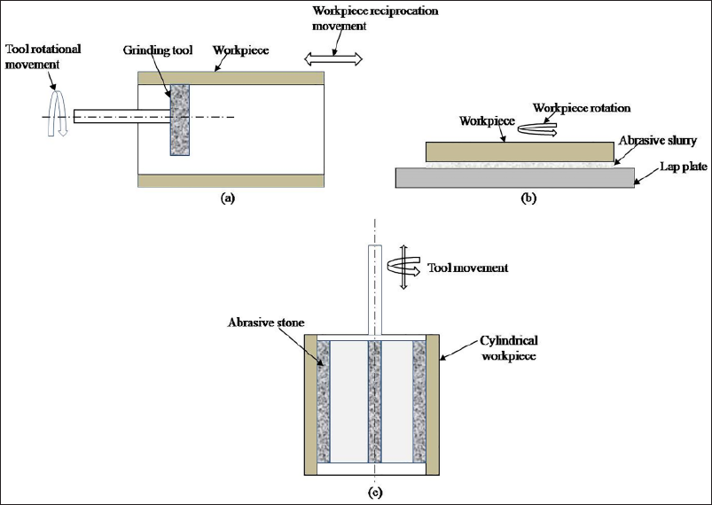
These processes are often employed in industries such as automotive, aerospace, and precision engineering to reduce the surface roughness (Ra) of various components upto certain limit. A solid abrasive tool is used in grinding to remove material to finish flat, cylindrical, or hollow surfaces. 3 While finishing, the abrasive particles of the grinding tool remove the materials in the form of chip particles under non-uniform finishing forces. In lapping, the two surfaces are rubbed together, where loose abrasives are cast off as a finishing agent at a normally low speed. 4 Products requiring strict tolerances for thickness, flatness, parallelism, or finish are processed using this method. One type of lapping is pressing brittle materials, such as glass, against abrasive materials, such as silicon carbide (SiC), jeweler’s rouge, or aluminum oxide, and then rubbing the glass itself against the iron surface. 5 The second form of lapping involves the rubbing of soft materials, such as pitch or ceramic charged with an abrasive, with a harder material (workpiece). Expanding abrasive stones of the right grit and grade against the work surface completes the finishing process in honing. Within the final surface, the stones are reciprocated and rotated. 6 When rotation and reciprocation are combined, the surface of the part being sharpened is covered in a crosshatch pattern. The issue faced with the above traditional processes is the lack of control over finishing forces. 7 Due to non-uniformity in the forces, the overall quality of the surface also results in non-uniform Ra values by producing surface defects such as pits, grooves, scratches, and others. Under advanced finishing techniques, magnetorheological (MR) finishing is highly considered to produce a defect-free surface on various industrial components. 8 The researchers have already created a platform for producing a super-finished surface quality on a variety of component forms, including flat, cylindrical, and 3D complicated, by developing various MR finishings. A MR polishing (MRP) fluid is another name for the smart fluid utilized in this finishing procedure. 9 Different materials, including grease, paraffin oil, iron particles, and abrasives, are mixed to create this fluid. The MRP fluid is gel-like during the first step, but it transforms into a wire brush structure when exposed to a magnetic field. 10 During finishing, this fluid performs finishing by rubbing its wire brush structure over the surface to be finished. The brief literature review regarding MR finishing is discussed below:
Using various magnetic configurations, the authors 11 evaluated the effectiveness of MR external finishing tools. The cylindrical copper workpiece was finished using MRP fluid, which is a combination of base fluid, abrasive powder, and iron powder. Iron and abrasive particles are present in a base fluid. According to the findings, after 60 minutes of finishing time, the Ra of curved cylindrical magnets decreased from 255 nm to 95 nm, while the Ra of flat cylindrical magnets decreased from 262 nm to 121 nm. The influence of MR finishing (MRF) fluid shear stress on workpiece thickness and magnetic field intensity was examined by the authors. 12 The results showed that with the decrease in thickness, the degree of magnetic field increases, whereas the shear stress increased for better clamping. Furthermore, the cutting forces were reduced to 14.3% with the proposed method in comparison to traditional clamping. The authors 13 developed a wheel-based magnetorheological finishing process (MRFP) technique to inspect the Ra and influence of residual stresses on oxygen-free high conductivity copper. The different variables that were the speed of the wheel, the working gap, and the feed rate were taken for this analysis. The author observed that as the working gap increased, a decrease in wheel speed as well as feed rate was observed, which further enhanced the Ra up to a Ra value of 15.5 nm while using a 6.9 MPa intensity of residual stresses.
The authors 14 experimentally investigated the Ra and the rate of material removed during finishing of fused glass silica through the ball end magnetorheological finishing process (BEMRFP) technique. The parametric approach was done with variables such as working gap, current, and tool rotations. The results concluded that a Ra value of 0.165 nm from 0.594 nm was observed with a current of 3A, a working gap of 1.2 mm, and tool rotations of 300 rpm. Using the Taguchi approach and the fuzzy gray relationship, the authors examined the impact of iron and abrasive particles in MRP fluid on surface quality. 15 The input parameters taken into consideration were the sizes of iron particles, the sizes of abrasive particles, different currents, and different working gaps during the overall 90-minute finish. The results revealed that the least Ra value was found to be 0.561 nm on Ni-P-coated SKD11 steel with iron particles of 0.4914 µm, abrasive particles of 0.7797 µm, a current of 0.6686 A, and a working gap of 0.7461 nm. The authors 16 investigated the effect of the temperature of the MR fluid on the polishing performance of the BEMRFP technique. The author developed a theoretical model, and correspondingly, the experiment was also done on a K9 glass specimen. The outcome demonstrated that polishing efficiency rose by 108.4% and the Ra value dropped to 14.9 nm from 202.2 nm at 60 °C with a high material removal rate. To obtain the optimum variables during MR finishing, a parametric study was performed. 1 The different variables, such as the rotational speed of the workpiece, mesh sizes of abrasives, and iron particles, were taken for brass surface finishing. The results revealed that with a rotational speed of the workpiece of 400 rpm, 600, and 200 mesh sizes of abrasives and iron particles, the maximum reduction in Ra was found as 77%.
The authors designed the blind hole MR finishing tool, 17 which was an enhanced version of the current tool structure. The EN-31 mold cavity was finished using the parameters of rotation of the cavity at 800 rpm, working gap of 2 mm, and total finishing time of 90 minutes. The findings showed that compared to the previous tool, the current tool improves surface quality on the inner vertical and inner bottom surfaces of the mold cavity by approximately 7.4% and 4.59%, respectively.
According to the literature review above, numerous studies have been carried out on MR finishing of wide varieties of components having internal, exterior, cylindrical, and flat shapes.18, 19 These studies generally overcome the limitations of either grinding, lapping, or honing processes. Somehow, there are likely no studies that have performed on miniature-shaped components (of hollow type) because a proper design of a tool is needed for producing a nano-scale finishing operation. But in the present study, a tool was made for finishing the internal surface of small-diameter tubes through MRP fluid.
Magnetostatic analysis
The magnetostatic analysis deals with the distribution of the magnetic flux in the working gap between the tool and workpieces. In this work, the magnetostatic analysis was also done with the help of Maxwell software. During analysis, the relative permeability was taken for the NdFe35 magnet as 1.0997, the MRP fluid as 5, and the copper workpiece as 0.9999. The magnet dimensions were taken as 20 mm × 20 mm × 20 mm (i.e., length × breadth × height), and the gap between the magnet and workpiece outer surface was taken as 1 mm. The working gap between the tool and workpiece was taken as 5 mm. The workpiece dimension was taken as 10 mm × 13 mm × 40 mm (i.e., internal diameter × external diameter × length). The magnetostatic analysis representing the distribution of the magnetic field can be clearly observed in Figure 2.
Magnetostatic analysis of the present tool with MR polishing inside the workpiece.
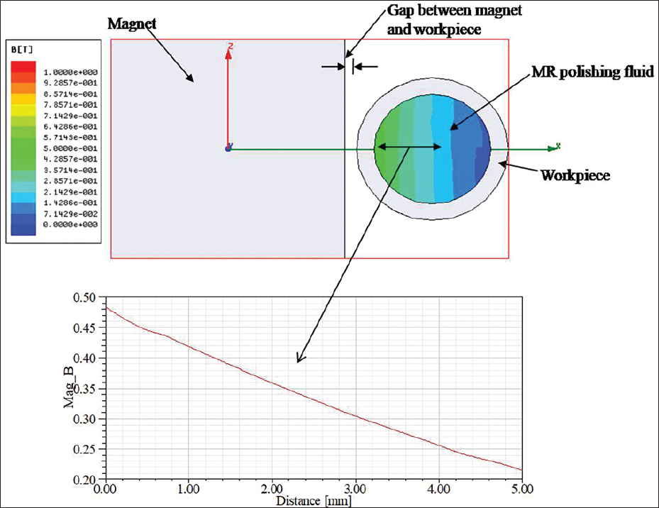
From the simulation, it was observed that the workpiece surface, which was near the magnet, was enriched with a high magnetic flux density, that is, 0.47 T, whereas it decreased toward the center of the workpiece, that is, 0.24 T. Under the region of 0.47T, the MRP fluid will be highly concentrated and perform the finishing operation. Both continuous workpiece rotation and tool reciprocation were used to shear the material on the interior surface of the workpiece.
Experimental setup and synthesis of polishing fluid
With a maximum spindle speed of approximately 1,300 rpm, a special-purpose lathe machine from Lotey Industries Pvt Ltd was employed for the finishing trials. The workpiece selected was a copper miniature-diameter tube of 10 mm external diameter, widely used in air-conditioning applications due to its excellent thermal conductivity. The experimentation was conducted over a 50 mm length of the workpiece. The actual photograph of the workpiece mounted inside the lathe chuck is shown in Figure 3(a). During finishing, the workpiece rotated in accordance with the spindle speed imparted by the chuck, while the reciprocal motion of the tool along the x-direction was enabled by fixing the experimental setup onto the lathe machine’s linear slide. The tool frame was fabricated from a rectangular aluminum plate, mounted at the tool-post location of the lathe machine. This frame was rigidly secured to an NdFeB permanent magnet, which generated a magnetic field strength of 0.24 T, through a bolt arrangement and a cylindrical bushing. The shape of the permanent magnet was taken as rectangular, based on the availability and better fitment in the setup. As illustrated in Figure 3(b), the magnet was fixed to the cylindrical bush using stud bolts. The tightening of bolts ensured proper alignment, thereby maintaining an accurate operating gap of 1 mm between the magnet face and the external surface of the 10 mm copper tube. The gap was measured using the tool gap measuring tool (stainless steel feeler gauge leaf). This arrangement ensured both stability and repeatability of the finishing process.
Actual photograph of (a) working mounted inside the lathe chuck, (b) MR finishing tool approaching the workpiece, and (c) synthesized MR polishing fluid.
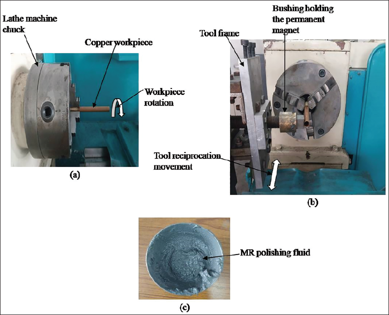
In this study, the internal surface finishing of a miniature-diameter copper tube was achieved primarily through the application of a specially formulated MRP fluid. The MR fluid was prepared in a mixing chamber by combining constituents in specific volumetric proportions: SiC abrasives (23%), electrolytic iron powder (EIP) (17%), and 60% of a base fluid, the latter comprising 80 wt% oil and 20 wt% grease. An actual photograph of the prepared MRP fluid is shown in Figure 3(c). This composition of the MRP fluid was considered based on an initial set of trial experiments performed on this setup.
To confirm the improvement in surface finish on the external surface of the copper cylindrical workpiece, Ra parameters were measured before and after MR finishing using a Ra profilometer (Mitutoyo Surftest SJ-210), with a cut-off length of 0.25 mm. The initial Ra was recorded at three different locations along the external cylindrical surface to ensure consistent and representative data for assessing finishing improvement. Following each MR finishing cycle using the developed finishing rig, Ra measurements were taken at the same locations to accurately compare changes and confirm the extent of surface enhancement.
During the finishing process, the MR fluid was introduced into the interior of the copper workpiece. Under the influence of the applied magnetic field, the suspended abrasive–ferro-particle chains were aligned and compacted, thereby enabling controlled material removal and imparting a smooth finish on the internal surface of the tube.
Material removal formation
Figure 4 shows a schematic illustration of the material removal mechanism used in the internal surface finishing of a small copper workpiece.
Formation of material removal using the currently developed tool.
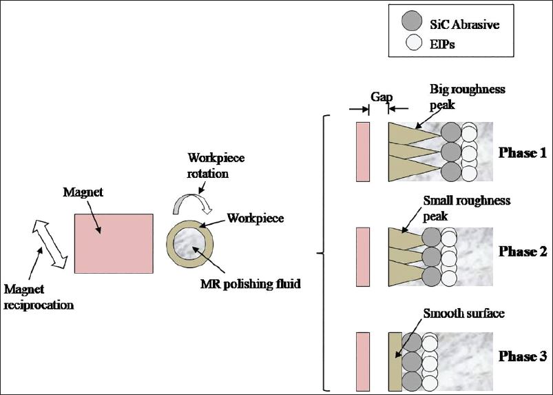
Initially, the workpiece internal surface contains big roughness peaks, as represented in phase 1. During finishing, the MRP fluid was inserted inside the workpiece, which came into action under the effect of a magnetic field. In phase 2, the abrasive particles present inside the fluid approach the peaks under the pressure of EIPs. In this, the big roughness peaks get cut-off into small roughness peaks. The MRP was conducted regularly to avoid the mixing of chips inside the fluid. Phase 3 involves the constant motion of abrasive particles across the workpiece surface, which eliminates the tiny peaks. Consequently, a smooth surface can be produced.
Optimization of process variables and experimental plan
The various process variables were taken for the plan of experimentation. The brief explanation of each process variable is shown below:
Workpiece rotation (rpm)
During finishing, the rotation of the workpiece was essential for producing the shearing effect of abrasive particles. The different workpiece rotations were taken, that is, 300 rpm, 500 rpm, and 700 rpm, against the % change in Ra value. When the workpiece rotates, the charged particles remove the unwanted materials from the workpiece surface under the shearing effect. The above values of workpiece rotation were taken from the existing literature review.
Tool linear speed (cm/min)
In relation to the percentage change in the Ra value, the various tool linear speeds were 10, 40, and 70 cm/min. The roughness peaks with lesser shearing forces can be sheared by using the minimum value of 10 cm/min, while the roughness peaks with larger shearing forces can be sheared by using the maximum value of 70 cm/min. The tool’s linear speed values listed above were determined using the available literature as a guide.
Finishing time (minutes)
Different finishing times of 40, 50, and 60 minutes were used to assess the percentage change in Ra value. The finishing time, which is 40 minutes, was taken as a minimum finishing time, whereas 60 minutes was taken as the maximum finishing time. The above values of finishing time were taken from the existing literature review.
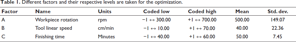
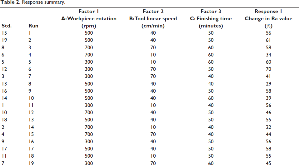
Using the SJ-210 surface test, it was discovered that the workpieces’ Ra values ranged from 259 to 280 nm during the experiment. After that, Design Expert 11 software was used to carry out the experimental plan. Table 1 shows the various components and the levels at which they were taken for the optimization study. According to the provided data set, 19 tests were conducted in total, and Table 2 displays the results of those studies.
Different factors and their respective levels are taken for the optimization.
Response summary.
Results and discussion
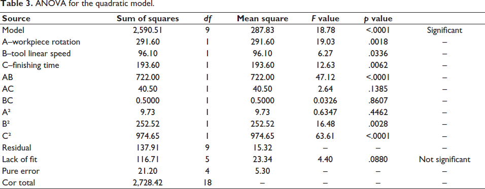
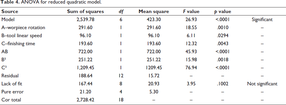
If the p value in the aforementioned analysis of variance (ANOVA) model is less than .05, the values are deemed statistically significant. The values are regarded as non-significant if the p value is higher than .05. Values such as A, B, C, AB, B2, and C2 were discovered to be significant in this model (as shown in Table 3). The values such as AC, BC, and A2 were found to be non-significant. Therefore, in the proper regression analysis, these non-significant values were to be removed. The ANOVA with a reduced quadratic model is depicted in Table 4. The substantial nature of the model is indicated by its F value of 26.93.
ANOVA for the quadratic model.
ANOVA for reduced quadratic model.
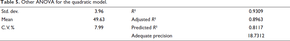
The statistical parameters presented in Table 5 summarize the adequacy and predictive capability of the developed quadratic model. The standard deviation of 3.96 indicates a low dispersion of the residuals, suggesting that the model predictions are close to the experimental values. The mean value of 49.63 represents the average response, and the coefficient of variation (C.V.) of 7.99%, being below 10%, signifies good precision and reliability of the model. The coefficient of determination (R²) of 0.9309 reveals that approximately 94.95% of the variation in the response is explained by the model, demonstrating an excellent fit to the experimental data. The adjusted R² value of 0.8963, which is close to the R² value, further confirms the significance and adequacy of the model terms without overfitting. The predicted R² of 0.8117 shows good agreement with the adjusted R², indicating satisfactory predictive capability for new observations. Moreover, the adequate precision value of 18.7312, which is well above the desirable threshold of 4, indicates a high signal-to-noise ratio and confirms that the model can effectively navigate the design space. Overall, these statistical results affirm that the developed quadratic model is both reliable and statistically significant for predicting the response within the studied range.
Other ANOVA for the quadratic model.
Following the total regression analysis, the final equation is expressed as Equation 1 in its coded form. Predictions on the response at specific amounts of each element can be made using the equation expressed in terms of coded factors. The factors are coded as follows by default: +1 for high levels and −1 for low levels. The coded equation can be used to determine the relative impact of the components.
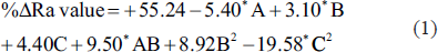
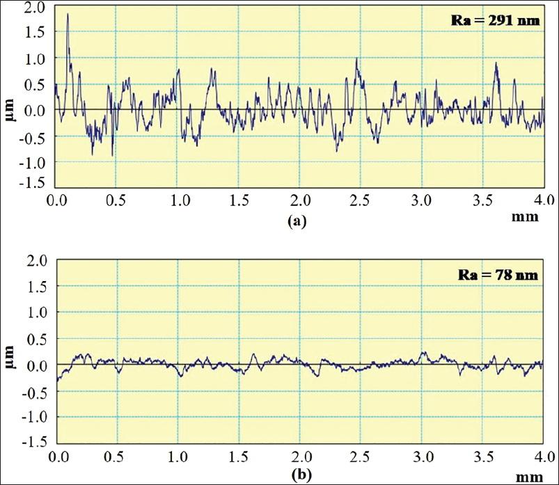
The current MR finishing method effectively reduced a maximum Ra change of 70% (from the beginning 291 nm to the final Ra 78 nm). Under ideal conditions—300 rpm workpiece rotation and 70 cm/min tool linear speed, as in Experiment Run No. 6—the target Ra of 78 nm was achieved within 50 minutes. The effect of individual process factors in relation to the percentage change in Ra value was covered in the ensuing subsections, which were very beneficial for determining the ideal value of each process variable.
Effect of workpiece rotation (A)
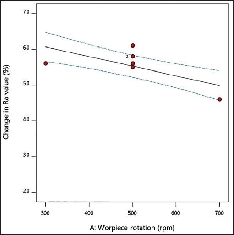
Figure 5 displays the effect of workpiece rotation (A) versus the percentage change in Ra value. The workpiece rotation (A) in this figure was adjusted between 300, 500, and 700 rpm, while the tool’s linear speed (B) of 40 cm/min and its finishing time (C) of 50 minutes stayed constant. The highest material reduction was seen at 300 rpm workpiece rotation, as opposed to 500 rpm and 700 rpm. At a rotational speed of 300 rpm, charged abrasives with sharp nose ends effectively removed surface peaks from the workpiece. However, at higher rotational speeds, their material removal efficiency decreased. This reduction in effectiveness is attributed to the increased relative speed between the abrasive particles in the MRP fluid and the surface peaks of the workpiece. As the relative speed increases beyond 300 rpm, the interaction time between the active abrasive particles and the surface features decreases. This shorter contact duration limits the ability of the abrasives to sufficiently engage with and remove material from the surface peaks, leading to diminished polishing performance. 18 Additionally, as the rotational speed of the workpiece increases, the magnetic field strength required to maintain the stability and effective confinement of the MRP fluid becomes insufficient. At higher speeds, the centrifugal forces acting on the fluid rise significantly, disrupting the controlled flow and alignment of abrasive particles within the magnetic field. This instability in the MRP fluid reduces its ability to exert consistent shear forces on the surface, further contributing to the decline in material removal efficiency and surface finish quality. 20
Effect of workpiece rotation (A) versus percentage change in Ra value.
Effect of tool linear speed (B)
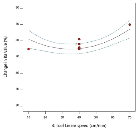
Figure 6 displays the tool’s linear speed (B) in relation to the percentage change in the Ra value. The tool’s linear speed (B) changed in this figure, going from 10 to 40 to 70 cm/min, while the other values, which are the workpiece rotation (A) at 500 rpm and the finishing time of 50 minutes, stayed the same. At 70 cm/min, the finishing was found to be better compared to 10 cm/min and 40 cm/min. The reason was that as the tool’s linear speed increases, the shearing phenomenon of abrasive particles hitting the roughness peaks occurs more efficiently and quickly. But as the speed decreases, the shearing phenomenon does not provide enough strength to erode the unwanted material from the workpiece surface.
Effect of tool linear speed (B) versus percentage change in Ra value.
Effect of finishing time (C)
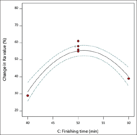
Figure 7 displays the influence of finishing time (C) versus percentage change in Ra value. The figure shows that while the other variable, workpiece rotation (A), remained constant at 500 rpm and the finishing time was 50 minutes, the finishing time (C) was adjusted to 40, 50, and 60 minutes. At 50 minutes of finishing time, the maximum unwanted material was removed as compared to 40 minutes and 60 minutes. With a lower finishing time, the workpiece roughness does not erode properly, but at a higher finishing time, that is 60 minutes, some scratches may be induced even after proper finishing, which further results in enhancing the Ra of the brass workpiece.
Effect of finishing time (C) versus percentage change in Ra value.
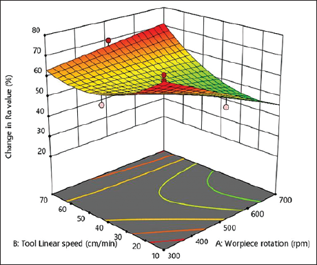
From the above subheadings, the optimum variables were found as workpiece rotation at 300 rpm, tool linear speed as 70 cm/min, and finishing time as 50 minutes, which final concluded that there was an overall 70% reduction of Ra value from its initial surface quality. The 3D contour plot between workpiece rotations (A) and tool linear speed (B) against the percentage change in Ra value is shown in Figure 8.
3D plot between workpiece rotations (A) and tool linear speed (B) against the percentage change in Ra value.
Confirmatory experimentation
From the above analysis, the optimum variables, that is, workpiece rotation at 300 rpm, tool linear speed at 70 cm/min, and finishing time at 50 minutes, were found, which concluded that the present setup was efficient in attaining nano finishing on the internal surface of the copper miniature workpiece. Therefore, for a clear examination of the final response, confirmatory experiments were done again with three experiments (taken from Table 5.2 randomly) to check the error between theoretical and experimental results. The final confirmatory experiments are depicted in Table 6.
Confirmatory experimentation.
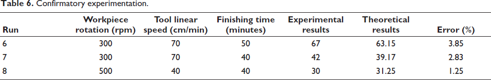
According to the aforementioned confirmatory studies, there was a minimum error of 1.25% and a maximum error of 3.85% when comparing the experimental and theoretical results. Figure 9 displays the Ra profile of the initial and final finished surfaces. The overall findings indicated that the current study was successful in producing an internal Ra on a tiny copper workpiece at the nano-scale.
Surface roughness profile of the initial and final finished surface.
Observations and comparative insights
Numerous studies have demonstrated the effectiveness of MRF processes—such as MR, MRF, and ultrasonic-assisted MRF—in significantly reducing Ra, from initial values in the micrometer or several hundred-nanometer range down to tens of nanometers (typically 60–100 nm or lower) under optimized conditions. Achieving these finer finishes generally requires longer processing times, higher magnetic fields or currents, smaller working gaps, and finer abrasive particles. In this study, MR finishing was applied to the external cylindrical surface of a copper workpiece. A Ra as low as 78 nm was achieved using a magnetic field of 0.24 T and a 1 mm working gap. Copper, being relatively soft compared to harder materials such as stainless steel (e.g., 316L) or titanium alloys (e.g., Ti-6Al-4V), is generally more amenable to fine finishing. However, the selection of process parameters remains critical to achieve sub-100 nm finishes. Recent literature features a variety of materials—including stainless steel, titanium alloys, aluminum (e.g., 6063), and copper—processed via MR-based techniques. Harder materials such as stainless steel and titanium typically pose greater challenges in achieving ultra-smooth surfaces due to their mechanical properties. Additionally, while some studies focus on external surfaces of components (e.g., shafts, cylinders), others target internal geometries (e.g., tubes or small mechanical parts such as nuts), which introduce complexities in tool access, uniformity of material removal, and deformation risks. There is also growing interest in the development and application of environmentally friendly MRP media, aimed at reducing issues such as oxidation and other negative side effects. The MR fluid employed in this work aligns with this trend, incorporating eco-friendly components without compromising performance.
Conclusions and future scope
The setup that was established in this study demonstrated its efficacy in achieving nanofinishing on the interior surface of a small copper workpiece. The following summarizes the study’s conclusions in brief:
In this parametric study, the tool developed was flexible, that is, it can mold according to the cylindrical dimensions of the work material. It can also finish tapered as well as stepped work materials. Hence, this tool may be called a multi-functional tool. The finishing setup made with a circular-curved magnetic structure was effective in achieving the mirror-quality surface finishing on the internal cylindrical surface of the miniature brass workpiece. Based on the final result, it was determined that, at workpiece rotations of 300 rpm, a tool linear speed of 70 cm/min, and a completion time of 50 minutes, the maximum percentage change in Ra value was 70%. The percentage error between the experimental and theoretical results was found to be between 1.25% and 3.85%.
The present study has the potential to expand into the following future domains.
The circular-curved magnets should serve as the foundation for the electromagnet-based tool’s exact finishing of different tiny cylindrical surfaces. It is possible to precisely polish many grades of materials, including brass and aluminum. Other parameters, such as varying SiC and iron particle mesh sizes, might be included in the optimization analysis.
Footnotes
Declaration of Conflicting Interests
The authors declared no potential conflicts of interest with respect to the research, authorship, and/or publication of this article.
Funding
The authors received no financial support for the research, authorship, and/or publication of this article.