
Abstract
Suspension smelting technology is emerging as a promising alternative in ironmaking to conventional hydrogen-based direct reduction (H-DRI) for low-carbon ironmaking. Unlike the slower solid-state reduction reactions in DRI processes, suspension smelting uses rapid in-flight reduction of fine iron ore particles. Within seconds, the ore fines undergo several process steps like heating up, phase transformation, reduction and partially melting, due to the high temperatures. This review explores hydrogen adaptation in suspension smelting technologies such as the flash ironmaking technology (FIT) and the HIsarna® process. The key reaction mechanisms, thermal decomposition and gas reduction with H2/CO, are examined through thermodynamic and kinetic analyses. A comparison of reduction kinetics between classical DRI processes and suspension smelting is provided, highlighting the significantly faster reaction rates of suspension smelting. Finally, the influence of the water–gas shift reaction and its potential negative impact on the reduction behaviour is analysed.
Introduction
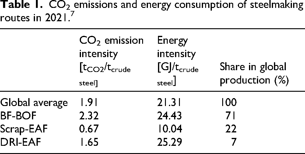
The steelmaking industry accounts for 7–9% of the global anthropogenic emitted CO2 emissions, 1 with an annual contribution estimated at around 2.6 Gt (2019). 2 The conventional iron- and steelmaking route is commonly based on either the blast furnace (BF) or the direct reduction of iron ores as the initial ironmaking step. 3 In 2019, the amount of pig iron produced by the blast furnace was 1208.7 Mt, while the amount produced by direct reduced iron (DRI) was 107.6 Mt, indicating the much stronger industrial presence of the blast furnace. 4 In BF ironmaking, iron ore is transferred to molten metallic iron, which can be directly cast to pig iron or mixed and treated with recycled steel in a basic oxygen furnace (BOF), whereas solid iron is produced by direct reduction, which is treated together with recycled steel in the electric arc furnace (EAF) to create molten steel. 3 Around 75% of iron used in the BOF steelmaking route is based on the BF hot metal, and around 25% is scrap. In contrast, the EAF can run on up to 100% scrap, but also utilise large shares of DRI.5,6 The World Steel Association summarises CO2-emissions and energy consumption for the main steelmaking routes. 7 Data from 2021 7 (Table 1) shows that most of the global steel production (71%) is based on the BF-BOF route. However, this route is responsible for high energy consumption and the most CO2 emissions. Even though DRI-based steelmaking shows (slightly) higher energy intensity compared to the BF-BOF route, its CO2 emissions are lower. Lastly, the recycling route using scrap as an input in the EAF shows the best environmental performance, both in terms of energy consumption and CO2 emissions. While recycling is clearly the most sustainable option, recycling alone cannot fulfil the ever-growing demand for steel. Hence, primary production will remain significant in the future. 8
CO2 emissions and energy consumption of steelmaking routes in 2021. 7
The conventional steelmaking route heavily depends on the use of carbon in the form of coal or coke as a reducing agent. 9 The EU aims to become carbon neutral by 2050 and to cut 55% of its emissions by 2030, 10 which forces the steel industry, as a large emitter, to move towards more sustainable production. Multiple strategies have been investigated to help reduce carbon emissions. Examples include the use of carbon capture and storage/use (CCS/U), the use of biomass in the reduction process, plasma-based iron ore reduction or electrolytic approaches. 11 Yet, the most popular approach to actively decrease the emitted CO2 from the production process is using green hydrogen to substitute carbon as a reducing agent for iron ore. 11 The adaptation of H2 in ironmaking processes could lead to various advantages compared to carbon-based reduction. First, pure H2-based reduction will only emit H2O. Secondly, H2 shows faster kinetics compared to carbon-based reduction, 9 resulting in a higher productivity. However, problems can also arise from utilising H2. In contrast to CO reduction, the reduction of iron oxides with hydrogen is endothermic, 6 requiring additional (external) energy supply to keep the high temperatures needed during the process. In addition, carbon is an essential component for the transition of iron to steel, which cannot be completely omitted. 12
To decrease the CO2 emissions arising from this intense use of carbon, hydrogen is increasingly investigated as a substitute. Ironmaking processes utilising hydrogen as a reducing gas can be classified based on the type and shape of input material, the reducing gas composition or furnace technology, where, for example, shaft furnace processes like MIDREX operate with pellets and fluidised bed applications like CIRCORED with fine ore as an input material. 13 Most H2 adaptation nowadays focuses on the DRI processes, where the shaft furnace is currently at the furthest state considering the technology readiness. 11 However, processes like HIsarna®, developed by Tata Steel, and the Flash Ironmaking process, developed by the University of Utah, are two new alternative ironmaking approaches based on the principle of suspension smelting.14,15 A significant difference of the suspension smelting process compared to the DRI processes is the much higher temperatures, which lead to a faster reduction, within seconds.15,16 Since such high temperatures are not achieved during DRI processes, the resulting reaction mechanisms differ and include thermal decomposition next to gas reduction. 15 Moreover, these processes are more flexible in their input material, leading to a more sustainable ironmaking by eliminating the material pre-treatment steps. 11 This review explores the differences between the two methods, covering H2 adaptation in both DRI and suspension smelting processes. 14 Next, the two reaction mechanisms in suspension smelting, thermal decomposition and gas reduction, are discussed in terms of thermodynamics and kinetics and compared to the more established DRI technology.
Hydrogen in DRI processes
DRI in shaft furnace
Direct reduction refers to the one-step conversion of iron ore to solid metallic iron using gas-based or coal-based reduction technologies. 6 In direct reduction ironmaking, gas-based reduction is responsible for over 90% of the annual DRI output.17,18 DRI is primarily used as feedstock for the EAFs or as a clean alternative to scrap iron in the BOF. 19 The most established DRI technology is the MIDREX process, operating in the shaft furnace. Around 60% of global DRI production can be assigned to it. It uses pellets or lump ore as input material and reformed natural gas (primarily hydrogen and carbon monoxide) as reducing agents. The raw material is charged into the furnace from the top, while the reducing gas is blown in at the middle. The exhaust gas leaves the shaft furnace at the top and is cleaned, cooled and reintroduced into the process. To create the reducing gases, the exhaust gas (containing H2O and CO2) is pressurised, mixed with natural gas, heated and passed through a reformer to produce CO and H2. After reduction, the DRI is discharged at the bottom of the shaft furnace. 19 The reducing gas composition in the MIDREX process contains 24–36% CO and 40–60% H2, with N2 as the remaining part. 17 To decrease emissions even further, natural gas can be mixed with pre-heated hydrogen before the reducing gas mixture is injected into the shaft furnace. This can decrease the use of natural gas in a MIDREX plant by up to one-third. 20 To achieve a complete transition from natural gas to hydrogen, ArcelorMittal is investigating a direct reduction demonstration plant based on the MIDREX process in Hamburg, Germany, in the framework of the H2 project. 21 The plant in Hamburg currently operates with natural gas. The objective is to utilise 100% hydrogen as reductant with a production of 100,000 tDRI/a by the end of 2025.21,22 Another commercial shaft furnace-based DRI process is HYL, operating with natural gas or coal-based (Energiron HYL). 23 An advantage of HYL is the possibility to recycle its reducing gases and recharge some H2 and CO back into the DR plant. 24 However, the production share of HYL is currently lower compared to MIDREX and accounts for approximately 15% of DRI output. 25
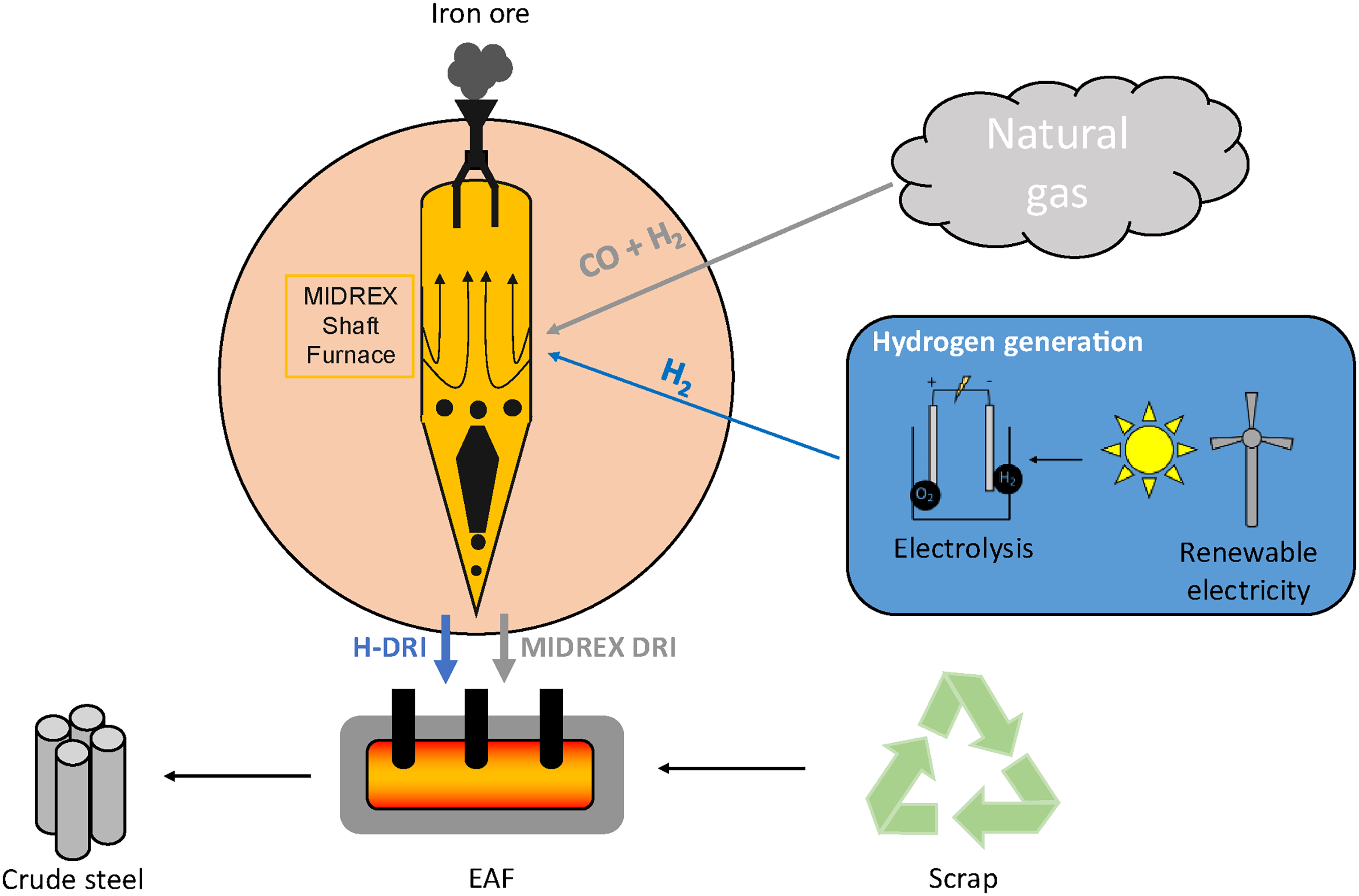
Figure 1 shows a general illustration of a possible decarbonised steelmaking route by hydrogen-based direct reduction (H-DRI) compared to natural gas in a classic MIDREX furnace, with the resulting DRI converted to steel together with scrap in an EAF. In this illustration, emissions are further reduced with the hydrogen supply to DRI generated based on electrolysis with renewable electricity. The hydrogen and iron ore are fed to the DRI process, resulting in either DRI or being made into hot briquetted iron (HBI) as output. The resulting product can then be fed into the EAF (with the option of adding more steel scrap), resulting in crude steel as a final product.
DRI in a fluidised bed reactor
In the framework of gas–solid reduction processes based on hydrogen as the reducing gas, fluidised bed (FB) technology is an alternative to shaft furnaces. The reaction takes place in fluidised bed reactor chambers, where fine iron ores and reducing gases are continuously injected and brought into contact with each other. 11 The use of fine ores as input material leads to further reduction in the environmental footprint since no prior agglomeration of the material is necessary, eliminating the CO2-emissions arising in these pre-processing step. 27 In general, fluidised bed technology can achieve higher metallisation (∼95%) compared to the shaft furnace (∼90%) due to less sticking problems of the fine ores compared to the pellets in the shaft furnace. 11 However, the application of fluidised bed technologies also brings disadvantages, leading to less market dominance than the shaft furnace-based processes. First, fine ores have a wide distribution of particle sizes, meaning that not all particles can be fluidised equally during the process. A second drawback is the trade-off between low and high temperatures during the process. While a high temperature leads to kinetic advantages and counteracts the endothermic reaction behaviour of hydrogen-based reduction, a lower temperature would prevent sticking of the fine ores during the process. 5 Industrial processes using fluidised bed technology are FINMET and the Metso Outotec CIRCORED. In contrast to the FINMET process, the CIRCORED process uses pure hydrogen as a reducing gas. 27 The CIRCORED process is based on a two-stage reduction process. First, the ores are treated in a circulating fluidised-bed (CFB) reactor. The CFB reactor can be defined as a pre-reduction stage, where 70% metallisation is reached. Since the reactions taking place in the CFB reactor are endothermic, energy is supplied by pre-heating the fine ores and through the combustion of natural gas and air. Processing of fine ores at high temperatures can lead to the sticking of the material. To prevent this, the CFB reactor only operates at 630 ˚C. Next, the material from the CFB is supplied to the second stage, the fluidised bed reactor. Here, final reduction takes place to achieve metallisation rates of 92–93% at temperatures of 850–900 °C. The off-gas from the second-stage fluidised-bed reactor is reintroduced into the CFB reactor as a secondary process gas. Briquetting requires a material temperature of approximately 700 ˚C. Therefore, the reduced iron is supplied to a flash heater before briquetting.13,14,28 If pure hydrogen is used, the final product of the CIRCORED process shows no carbon contents. 13
Smelting reduction ironmaking
Even though the dominant trend in Europe is moving in the direction of establishing H-DRI processes for ironmaking,2,29 smelting reduction is another alternative that can reduce the carbon footprint of iron production. Smelting reduction currently accounts for 7.5–7.8 Mt iron per year, 17 a much lower number compared to the 1354 Mt (2021) produced by the blast furnace and 114 Mt (2021) produced by DRI technology. 14 The COREX and FINEX processes (illustrated in Figure 2) are the only commercially available smelting reduction installations. In general, smelting reduction combines an iron ore pre-reduction step, followed by smelting in a reactor without coke usage. The product is liquid pig iron, which is comparable to the hot metal exiting the blast furnace. 6 The initial pre-reduction stage follows the DRI principle and can be performed in a shaft furnace (Figure 2(a)) or fluidised bed (Figure 2(b)), at comparable low temperatures (800–900 °C). However, it is now followed by a melting stage (Figure 2(c)) operating at a much higher temperature of 1000–1800 °C, depending on the zones of the melting reactor. 30 Another difference from the DRI processes is the ratio of CO and H2 in the reducing gases. In smelting reduction, the hydrogen content is usually much lower. 17 The hydrogen content in COREX is 20–25% 14 and therefore relatively lower than the 40–60% in MIDREX. 17
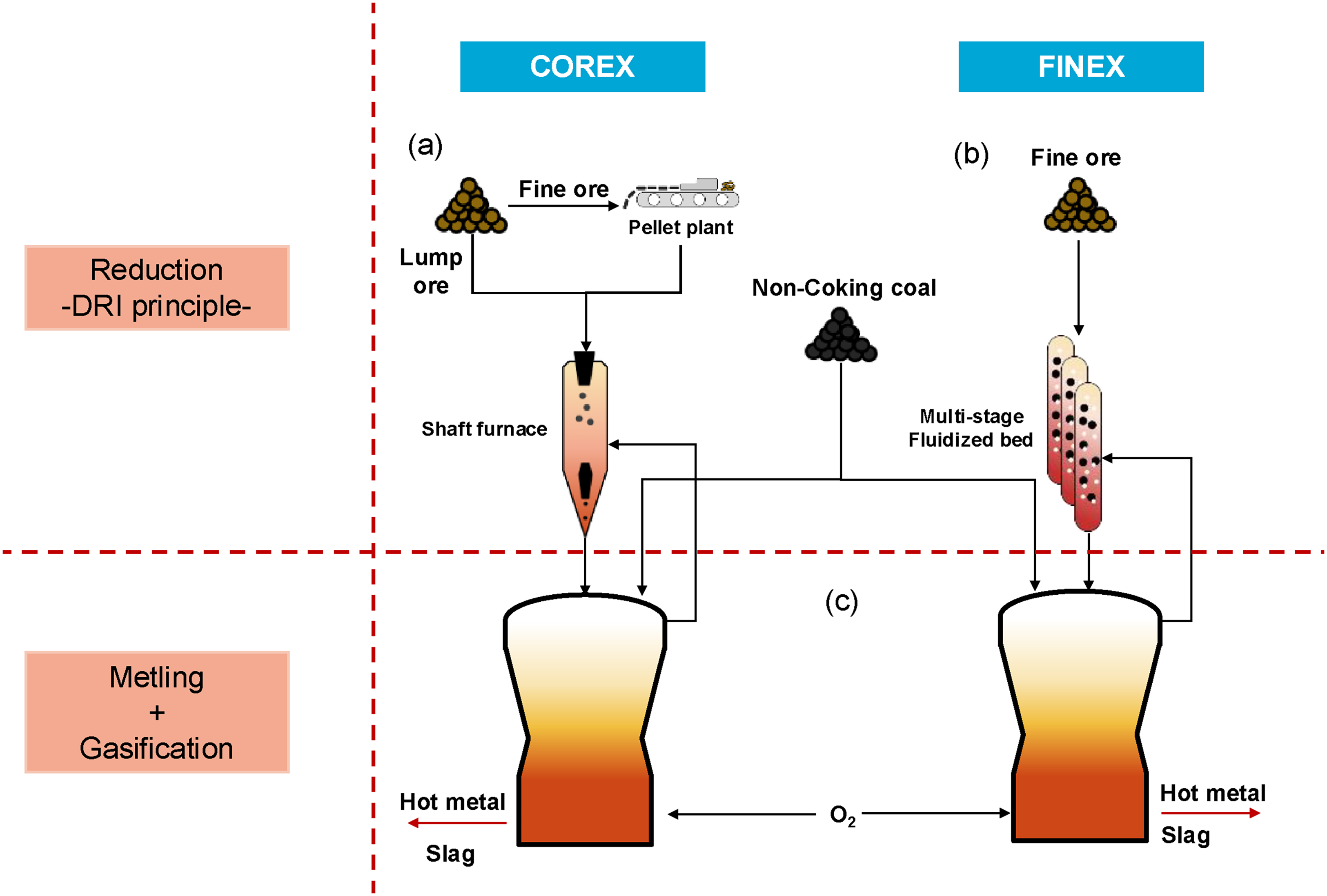
Simplified presentation of a COREX and FINEX process, adapted from 14 with permission from Elsevier.
The COREX process is commercially the most common form of smelting reduction. 6 A commercial example of COREX implementation is JSW (Jindal South West) Steel in India, implementing the world's biggest COREX-based DRI plant (2014). 31 COREX works in two stages. In the first step, the reduction from iron ore to sponge iron takes place. This pre-reduction works according to the shaft furnace principle with CO and H2 as reducing gases. The reducing gases are obtained by the gasification of coal with a resulting composition containing 65–70% CO, 20–25% H2 and 2–4% CO2. The reduced iron ore is then melted during the second step in a melter-gasifier. The resulting heat, from the coal combustion, is used to melt the reduced ore, which drops from the shaft furnace to the melter-gasifier. The hot gas then leaves the melter-gasifier and is mixed with a cooling gas to reach a temperature of 850 ˚C. After purification of the gas, it is fed back to the shaft furnace as a reducing gas. 6
The FINEX process can be considered as a variant of the COREX process, where the first commercial plant of POSCO (Pohang Iron and Steel Company) in Pohang started operation in 2007. The main difference is that the FINEX process uses fine ore, while COREX uses lump ore and pellets. Furthermore, the reduction process is based on the fluidised bed principle instead of the shaft furnace. 6 Generally, FINEX operates as a four-unit process with a multi-stage fluidised bed reactor as pre-reduction steps, hot-compacting, coal-briquetting and a melter-gasifier needed for the final reduction. 32 Compared to the shaft furnace approach of the COREX process, the fluidised bed approach leads to a better contact between the reducing gases and the material. The more uniform gas flow and ore distribution lead to more even reduction degrees of the material compared to the pellets in the shaft furnace. 32 FINEX allows to operate with low-cost fine ores with a higher content of iron oxide, thereby reducing costs and emissions for the input material and generating gases which can be reused in power generation and metallurgical applications. 33 To further reduce CO2-emissions, POSCO plans to continue the transition from coal to H2 as reducing agent in its ironmaking processes by 2050. 33 The newly planned HyREX approach, based on FINEX technology, will help POSCO achieve carbon neutrality. In this new approach, DRI will be produced in fluidised bed reactors with 100% H2 (compared to the current 25% H2) before being processed in an EAF to molten iron.34,35
Another commercially available smelting reduction technology is HIsmelt, developed by Rio Tinto. HIsmelt is a single-reactor smelting reduction process, currently operating in China (Molong plant).14,36 Before being injected into the smelting bath, fine ores can be pre-heated and partially reduced, for example, by means of a two-stage circulating fluidised bed reactor.37,38 In the HIsmelt reactor, reduction and melting of pre-reduced fine iron ores occur simultaneously.39,40 The fine ores, fluxes, and coal are injected directly into a molten metal bath (∼1673 K), which is covered by a layer of molten slag. The injection is performed via water-cooled lances, while a hot oxygen-enriched air blast post-combusts the off-gases generated during iron oxide reduction. 36 The submerged injection of the solid reagents further induces stirring, causing slag droplets to erupt into the upper regions of the reactor, promoting heat transfer from the post-combustion zone into the liquid slag/metal zone.36,39
At the Molong plant (in operation since 2016), rotary kilns are used for the pre-treatment of the ores. The first kiln dries the hematite ores, while the second heats them up to around 1073 K using pulverised coal combustion. 36 An advantage of HIsmelt over the blast furnace is its ability to process ores with high phosphorus content without significantly increasing the phosphorus content in the liquid iron, due to the more oxidising conditions in the reactor. 39
From a sustainability perspective, HIsmelt theoretically allows partial substitution of coal with H2.37,41 However, no industrial implementation exists to date. 37 Other potential improvements include the use of sustainable biomass (converted to biochar) to replace coal, enrichment of H2 during the ore pre-reduction, or CO2-capture from off-gases. 41
Suspension smelting ironmaking
Two new approaches currently under development utilise a method known as suspension smelting ironmaking. The reduction part of the process takes place in suspension, using flash or cyclone processes, leading to the reduction of iron ore fines at high temperatures and short particle residence times (seconds). 42 One such process under development is the flash ironmaking technology (FIT), which is investigated at the University of Utah.43–48 In the FIT, iron ore concentrates are reduced in a flash reactor using reducing gases such as hydrogen, natural gas, bio/coal gas or their mixtures. In the case of natural gas and pure hydrogen, the injected mixtures are H2 + CO + H2O + CO2 and H2 + H2O, respectively. This technology could be scaled up to industrial applications with the prerequisite that the concentrate is smaller than 100 µm. 16 In terms of energy efficiency and emission savings, the advantages of this technology arise from the input material, since no agglomeration or coking steps are necessary as pre-treatment. Another advantage is the very short residence times (only seconds) needed for reduction at the operating temperatures of 1473–1873 K. 16 Total energy savings using FIT are expected to be around 38% compared to the traditional blast furnace route. 48 An additional advantage is the combination of the two steps previously discussed in smelting reduction. 44 The process could be established in an overall continuous direct steelmaking route, leading to products in either molten- or solid state for EAF steelmaking. 16
The development of FIT started in 2005, primarily at the University of Utah with support from the US Department of Energy. 48 The article by Sohn, Elzohiery and Fan 49 provides a comprehensive overview of the research progress achieved within FIT-related projects. Early studies focused on understanding reaction kinetics under FIT conditions and on formulating reduction rate equations in the temperature range of 1423–1873 K.50–54 These investigations demonstrated that high metallisation degrees of magnetite fine ores could be achieved within seconds. Building on the kinetic analysis, studies were subsequently conducted utilising a laboratory flash reactor operating at temperatures between 1423 and 1473 K.55–57 Applying H2–H2O mixtures, reduction degrees exceeding 90% were obtained. In contrast, experiments employing post-combustion of methane with pure oxygen generated reducing gas mixtures of H2 + CO + H2O + CO2, but resulted in lower overall reduction degrees (approx. 80%).
In a subsequent step, upscaling of the process to pilot scale was investigated. The pilot flash reactor, with a reactor volume of 1.01 m3, was operated at temperatures between 1473 and 1823 K and material feeding rates ranging from 1 to 7 kg/h. The pilot-scale experiments demonstrated good reproducibility, and complete reduction was achieved at temperatures between 1573 and 1673 K using H2 with an excessive driving force of 1.51, a fine ore feeding rate of 5 kg/h, and a nominal particle residence time of 14.6 s. Overall, these results indicated the technical feasibility of up-scaling FIT towards industrial iron production.49,58 To further support the scale-up efforts, a CFD (Computational Fluid Dynamics) model of the laboratory flash reactor was extended and refined based on the experimental findings obtained from the pilot-scale reactor. 59 Despite FIT being regarded as a promising technology for next-generation, low-emission ironmaking, challenges remain with respect to large-scale implementation. To the author's knowledge, no additional upscaling efforts beyond the pilot-scale investigations reported in the literature have been made public.
Another process utilising the principle of suspension smelting is the HIsarna® process. HIsarna was developed in the framework of the ULCOS (ultra-low-CO2-steelmaking) initiative.
14
The initiative (2004) aimed to reduce 50% of CO2 emissions per ton of steel in a production based on iron ores as input material.
60
As part of the initiative, a pilot plant was built at Tata Steel in IJmuiden (Netherlands), with construction completed in 2010. The hot metal capacity of the pilot plant is approx. 65 ktpa (∼8 t/h).
61
HIsarna combines the two process steps of a cyclone converter furnace (CCF) and a smelting reduction vessel (SRV) into a single furnace (Figure 3), operating in a counter-current principle, where the injected iron ores are in contact with the hot processing gases.
62
Overall, HIsarna can be categorised as smelting reduction technology, due to final melting in the SRV, which is based on HIsmelt technology.
14
However, the mechanism occurring in the CCF (top part) of the furnace can be compared to suspension smelting. HIsarna operates by injecting the iron ores at the top of the CCF section of the furnace, together with oxygen and potentially also fluxes.
63
The upcoming off-gases from the SRV containing pre-heated H2 and CO gases result in the pre-reduction and even melting of the injected ores, since temperatures in the CCF can reach up to 1773 K.
63
Due to the high temperatures, two reaction mechanisms can influence the reduction of the injected ores: thermal decomposition and gas reduction.
15
The gas reduction ability of the SRV off-gas is described by the post-combustion ratio (PCR) that gives the percentage of the total CO and H₂ that was converted to CO₂ and H₂O, as in equation (4.1)
62
:
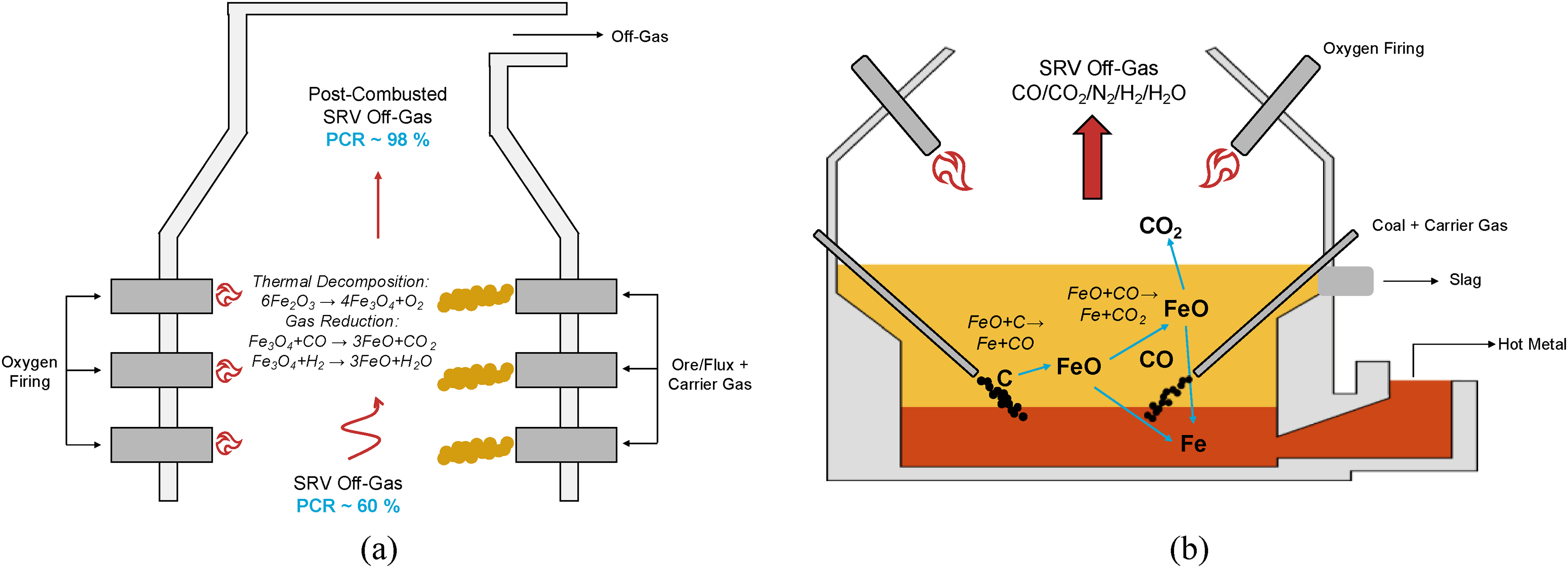
Schematic of HIsarna process with (a) the CCF top and (b) the SRV bottom section shown separately, adapted from 63 , CC BY 4.0 license.
When the off-gases from the SRV enter the CCF, the gas composition is characterised by a PCR of around 60% and usually contains more CO (∼32%) than H2 (3.4%). 63 While reacting with the injected ores, the off-gas is further oxidised, reaching PCR values of around 98% at the end of the CCF, consisting of mainly CO2 and H2O and only marginal amounts of reducing gases. 63 In the CCF section, reduced ore exhibits pre-reduction degrees of 20–25%, which indicates FeO as the main product. Following the pre-reduction, the molten droplets directly fall into the SRV section, where the final reduction to liquid iron is achieved by the injection of coal into the molten bath. 64
Hot commissioning and the first pilot campaign (campaign A) were carried out in 2011. Between 2011 and 2014, a total of four pilot campaigns (A–D) were conducted, each consisting of multiple production runs over several months. The main objective was the verification of the technical feasibility and stable operation of HIsarna. These campaigns further revealed high flexibility in raw materials quality (including steel scrap, dust and sludge utilisation) and supplied the first hot metal to a BOF plant. 61 Campaigns B and C specifically aimed to improve the production rate compared to campaign A, to increase the run length, and optimise key parameters such as the PCR, oxygen distribution in the reactor and coal injection. The increase of PCRs from approx. 80% to 90–95% was achieved and led to higher production rates (up to 6 thot metal/h) and reduced specific coal consumption. During these campaigns, the influence of ore particle size and dust losses was quantified and stable hot metal chemistries with very low Si (<0.02%), Mn (<0.02%), and P (0.015–0.03%) contents were demonstrated. 65 After the conclusion of campaign D, the main objective was to demonstrate the industrial feasibility of the process, and therefore demonstrate strong CO2 reduction potential at long runs with stable operation. To achieve this, the pilot plant underwent major upgrades between 2014 and 2017. These changes were, for example, the off-gas handling system, addition of raw materials handling and preparation area, and a scrap handling system. 61
In terms of environmental footprint, HIsarna provides the same advantages as FIT due to the direct production of liquid hot metal from iron ores without pre-treatment of the coke (coking) or ore agglomeration. 39 In combination with CCS technology, HIsarna can save up to 80% of CO2-emissions compared to the traditional blast furnace ironmaking. 14 In order to further improve HIsarna from an environmental perspective, it is possible to partly substitute the injected coal with biomass, natural gas or hydrogen. 66 Earlier studies indicated the potential to replace around 40% of fossil coal with the more sustainable charcoal. Even though complete removal of the solid carbon source is not possible for HIsarna to guarantee carburisation of the hot metal, injection of gaseous reducing agents (CH4, H2) could further improve the process. 66 Another advantage of HIsarna is the flexibility in the input material, since it is also possible to use low-grade ores and secondary materials from the steel production.62,66 The first pilot plant trials utilising scrap and biomass-derived charcoal were conducted in 2017–2018, as part of the H2020 LoCO2Fe project, demonstrating low CO2 potential (55% lower than HIsarna base case). Stable operation with up to 37% hot metal produced from scrap and up to 42% renewable carbon input was achieved. 61
More recently (2022), accumulated pilot data have been used to develop fundamental process models for HIsarna, describing the chemical, physical and thermodynamic phenomena of the process. This model is used to support further up-scaling of the process by combining theory with plant data. The model divides HIsarna into two parts, consisting of the ‘main process’ and the ‘secondary process’. The two parts consist of seven zones. The main process includes the hot metal (zone 1), slag (zone 2) and evolved gas (zone 3), while the secondary process includes metal splash, char and volatiles above the slag layer (zone 4), metal droplets in the slag layer (zone 5), the surplus carbon in the metal (zone 6), as well as the process gases from both the smelting and pre-reduction section (zone 7). 67 In 2025, following the successful pilot-scale operations and trials in IJmuiden, Tata Steel has approved the initiation of engineering and regulatory activities for a 1 million t/a HIsarna demonstration plant in Jamshedpur (India), signalling its strategic intent to advance the low-carbon technology towards industrial development. 68
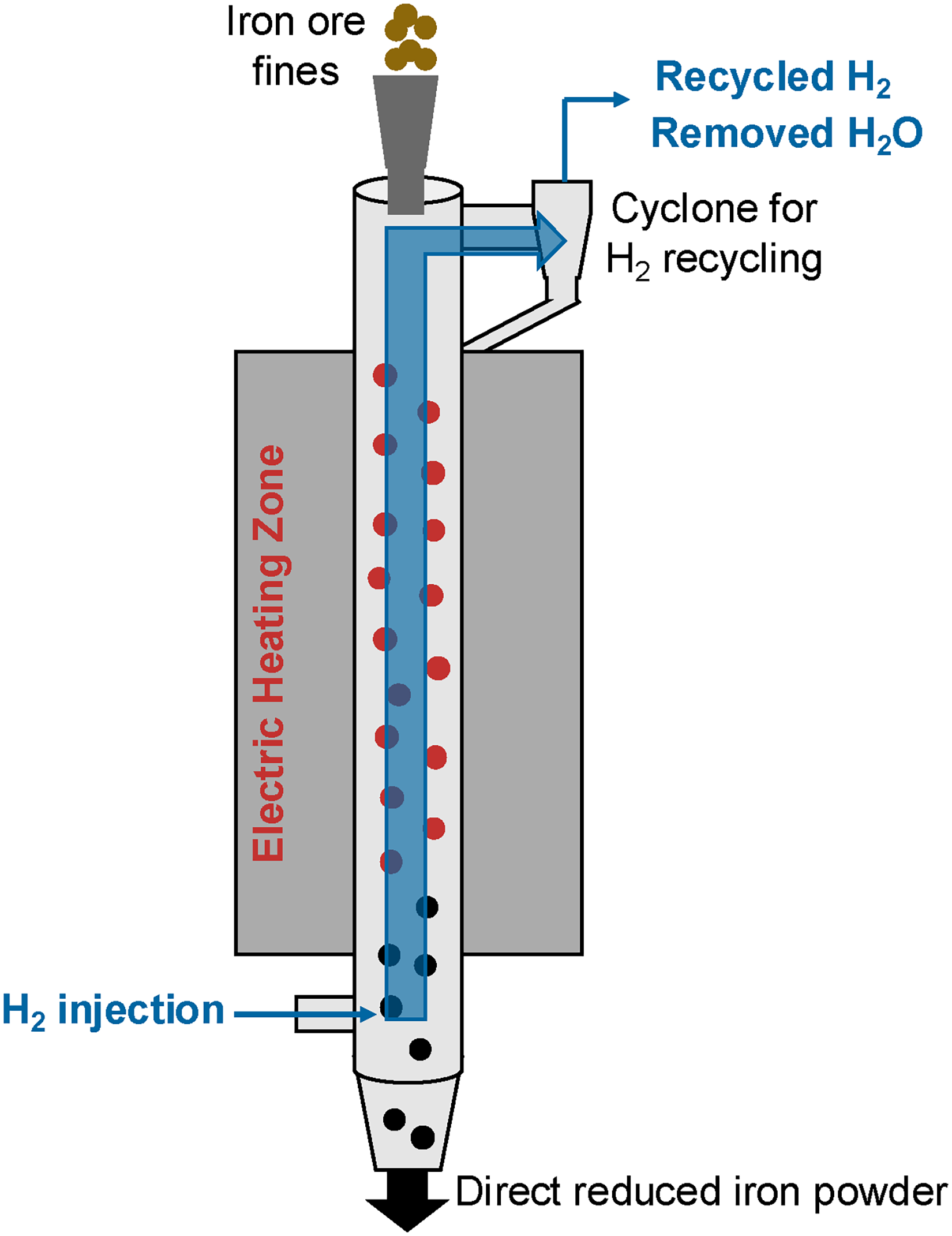
Another process worth mentioning in the framework of flash ironmaking technologies, utilising H2, is ZESTY (Zero Emissions Steel Technology) (Figure 4), which is currently under development and tested in pilot plant scale by Calix in Australia.69,70 Due to its lower reaction temperatures of 950–1100 °C compared to HIsarna and the FIT, the ZESTY process creates a DRI powder product, even though it follows more the principle of the flash ironmaking technology.70,71 Therefore, ZESTY doesn’t operate in suspension, but in the temperature range of classic DRI processes. Pilot testing has been done with a large range of particle size distributions (<500 µm) of several Australian iron ore samples, where most were mixtures of hematite and goethite, but also ores with magnetite as the iron-bearing phase.69–71 The iron ores are fed from the top using a screw feeder and are reduced over the length of the furnace (18 m) by H2, flowing in counter-current contact with the ores. The product is water-cooled to stop the following reactions. 70 With approximate residence times of 60 s, the reduction is longer compared to the FIT and pre-reduction in HIsarna, but significantly shorter than the reduction in a MIDREX shaft furnace, which can take several hours. 70 In pilot testing, ZESTY was able to achieve high metallisation degrees of 98%. The tested magnetite ores achieved lower metallisation compared to the hematite/goethite mixtures, explained by lower surface area and porosity. 69
Comparing HIsarna and the FIT to other smelting reduction processes like COREX and FINEX, the main difference is the pre-reduction of the ores. While in COREX and FINEX, pre-reduction is based on the DRI principle, HIsarna and FIT rely on suspension smelting technology, in which the ores are pre-reduced at significantly higher temperatures and shorter residence time, making use of the accelerated kinetics of gas reduction and thermal decomposition at high temperatures. 15 The following sections discuss in detail the two reaction mechanisms, namely, thermal decomposition and gas reduction, responsible for reduction in suspension smelting and compare them to the reduction mechanisms in DRI processes.
Reaction mechanisms in suspension smelting
Due to the much higher temperatures in suspension smelting ironmaking, thermal decomposition of the iron ore plays a crucial role in addition to gas reduction. In considering the thermal decomposition, it is important to account for the presence of multiple iron-bearing phases in the ore. Some interesting ores to consider from an industrial perspective are magnetite (Fe3O4), hematite (Fe2O3) and goethite (FeO*OH), while many others are mined as well. 14 The main reactions of interest are the dehydration of the goethite phase, as well as oxygen removal from the hematite phase, which are discussed separately.
Thermal decomposition of goethite
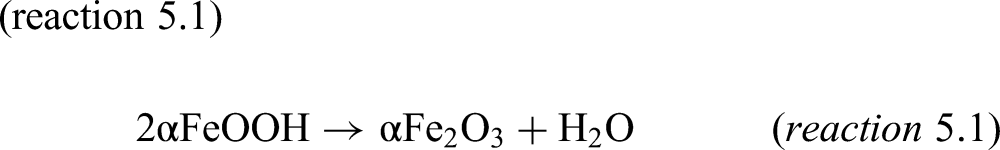
At relatively low temperatures, goethite transforms into hematite under the release of water–vapour, following (reaction 5.1)
72
:
The temperature range of goethite thermal decomposition has been studied by Walter et al. 73 for several goethite ores with varying particle sizes and specific surface areas. They determined that the initiation temperature for dehydration varies between 465 and 523 K and found a single or two-stage decomposition process, depending on ore properties (specific surface area and particle geometry). The peak temperature varied between 545 and 551 K for the first stage and between 578 and 595 K for the second stage. Ammasi 74 investigated the decomposition for several heating rates and observed similar initiation temperatures, with complete conversion occurring between 593 and 623 K (higher temperature corresponding to higher heating rates).
Several experimental studies75–78 have been conducted under non-isothermal conditions to determine the kinetic parameters and mechanisms of the goethite dehydration, with the results of selected studies presented in Table 2. Przepiera and Przepiera
77
described goethite decomposition based on (reaction 5.2), in which the removal of water first creates an amorphous hematite phase before forming crystalline hematite at increasing temperature.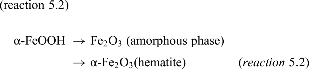
Kinetic findings of goethite thermal decomposition.
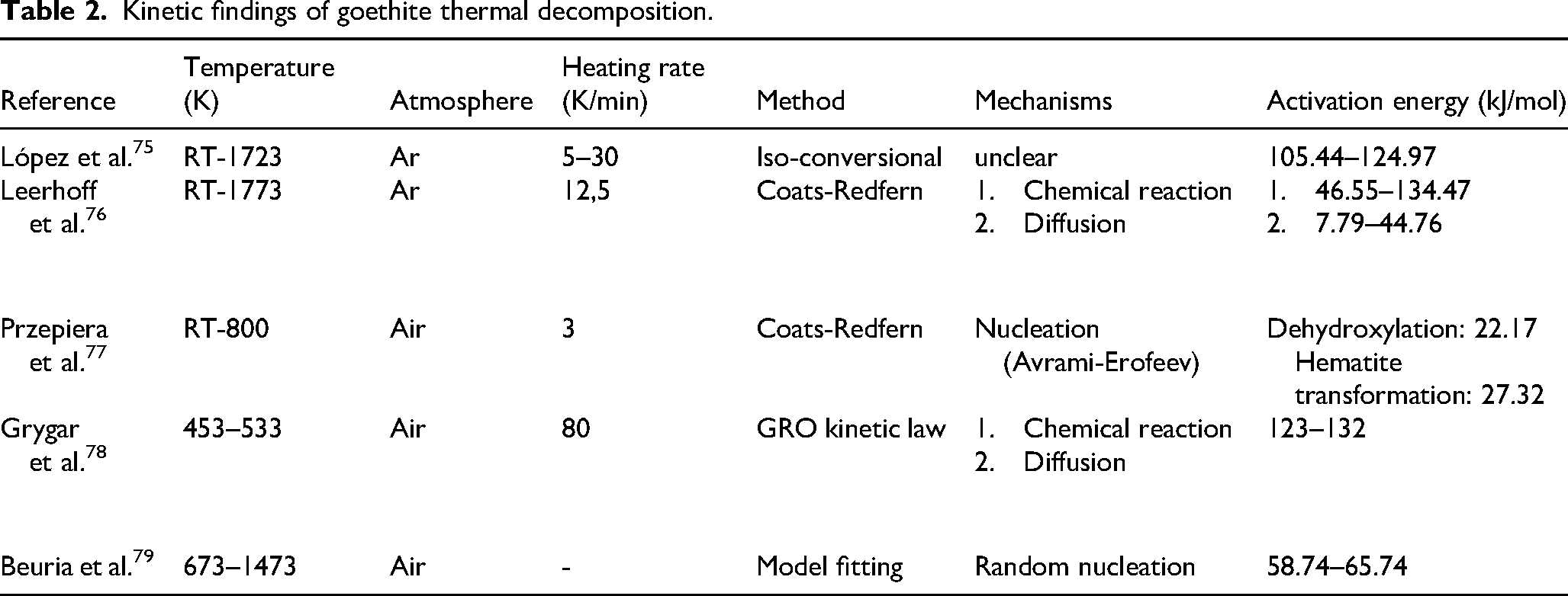
They determined that the overall decomposition reaction is controlled by nucleation. Grygar et al. 78 and Leerhoff et al. 76 also reported a two-stage decomposition of goethite but proposed separate mechanisms. Both identified chemical reaction control in the first stage and diffusion in the second. Other studies, such as Beuria et al. 79 suggest that the overall reaction is governed by nucleation in isothermal conditions. While the studies which report nucleation as a dominant mechanism77,79 indicate lower activation energies, the values of Beuria et al. are comparable to Leerhoff et al. for ores with lower goethite content during the reaction-controlled stage. In contrast, Grygar et al. reported significantly higher activation energies across both stages. Leerhoff et al. further found that an increasing goethite content in the ore raises the activation energy for the chemical reaction controlled, but reduces it for the diffusion-controlled stage. These results indicate that the amount of goethite in the ore does not have an influence on the decomposition mechanism, but on the activation energy needed to initiate the stage-dependent reaction.
Strezov et al. 80 studied the influence of goethite transformation to hematite on the structural changes within the ore particle. Their proposed mechanism, based on initial findings from Ariyama et al. 81 is presented in Figure 5. They observed diameter increase upon heating, with a volume expansion of 110% at 673 K and 112.5% at 1173 K (measured with a custom-designed spring-loaded linear velocity displacement transducer). This was followed by cracking of the particle, which they assigned to the formation of water–vapour.
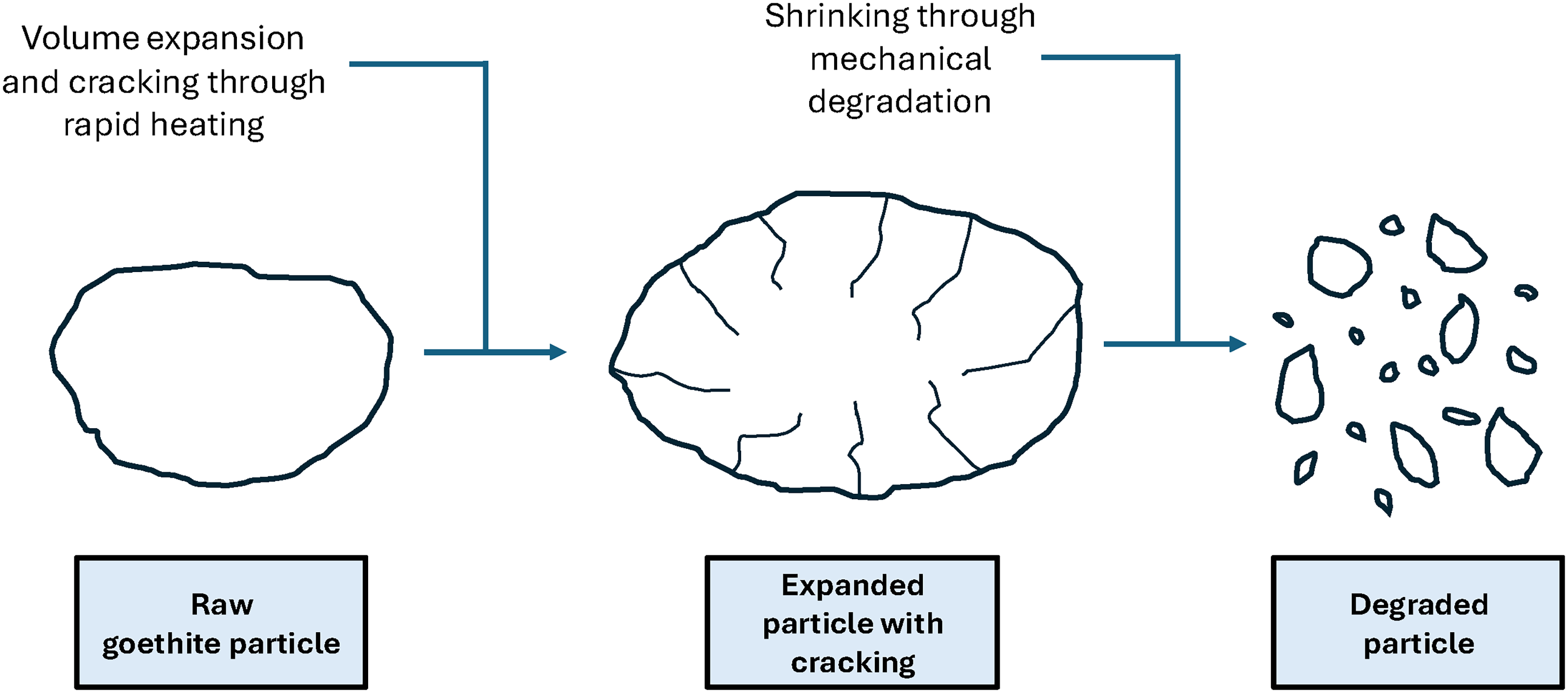
They found that most strain occurs at the particle surface, reaching up to 20% of its depth. They further found the influence of dehydration on the particle size of the goethite particle to be dependent on the initial particle size. For a particle size between 1.5 and 10 µm, the particle size decreased and for a particle size of 40–100 µm the particle size increased. This indicates that the expansion and not the fragmentation to finer fractions was the dominant effect. A change in material properties after heating was also observed by Li et al., 82 who studied the behaviour of fluxes and goethite ore during sintering. During the heating stage, crack formation on the goethite ore was observed once more, which led to a more porous structure. This change in the particle structure enhanced the diffusion of the fluxes during the process. Murakami et al. 83 found a link between the water content in the ore and the affected surface area during heating. A higher amount of water led to a higher specific surface area at a heating temperature of 673 K. Upon further heating the goethite to 1073 K, the specific surface area still increased compared to the raw material but decreased compared to the values measured after heating to 673 K, which they explained by the formation of larger pores at higher temperatures as also proposed in the study of Hirokawa et al. 84
Thermal decomposition of hematite
Iron can be present in different oxide states, namely hematite (Fe2O3), magnetite (Fe3O4) and wustite (FeO), depending on the applied temperature and oxygen potential. Besides their composition, these iron oxides differ in their thermal stability. Magnetite exhibits the highest melting point (1870 K), followed by hematite (1838 K) and wustite (1644 K).
85
From a thermodynamic viewpoint, the thermal decomposition and gas reduction of the hematite phase describe the same fundamental principle: the removal of oxygen from the iron oxide. The main reactions of hematite thermal decomposition are shown in (reaction 5.3) and (reaction 5.4)
86
: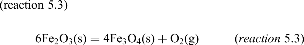
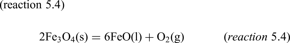
Figure 6 shows calculations for the thermal decomposition of 100 g pure hematite in an argon atmosphere, calculated with the equilib module of FactSage 7.0. 87
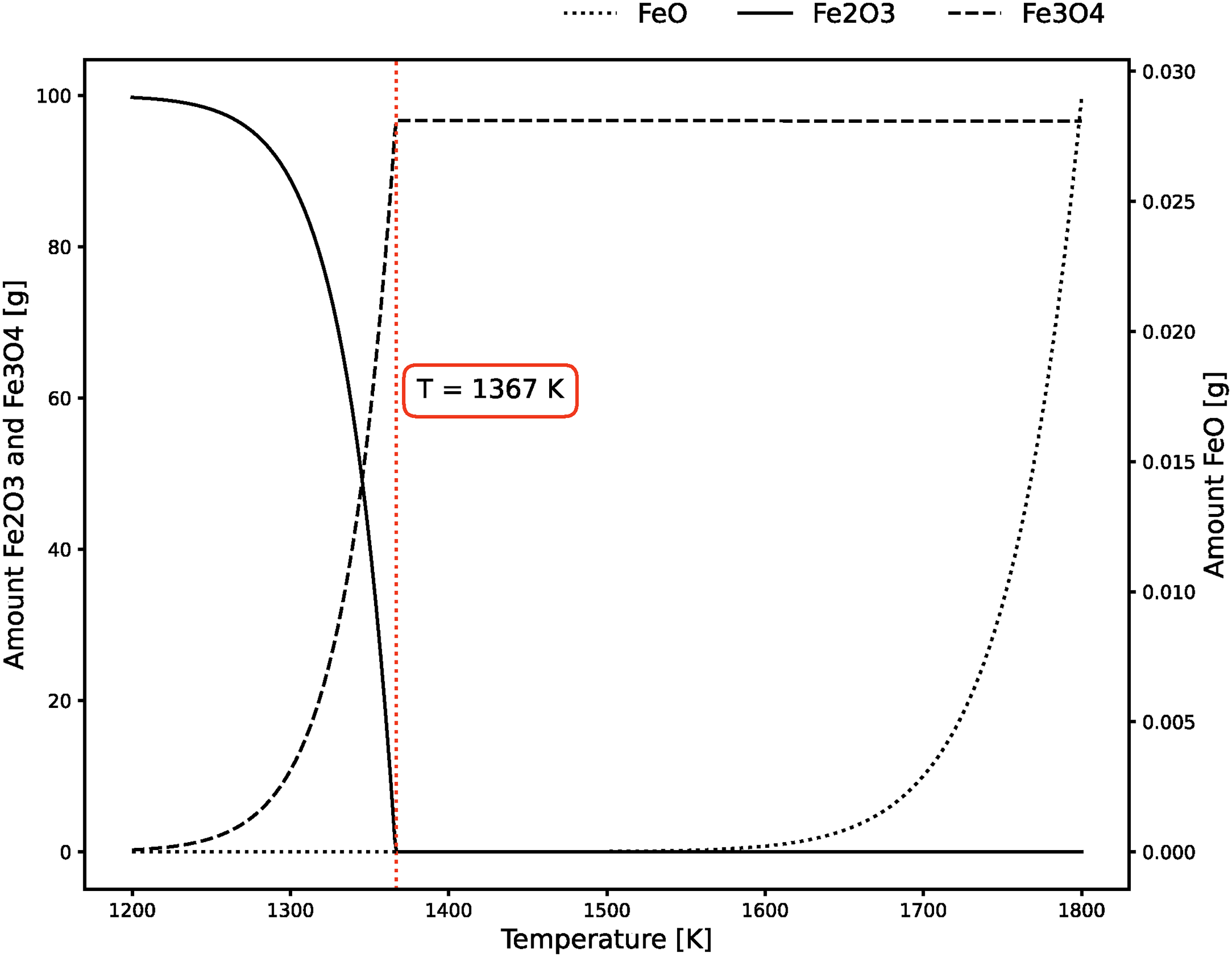
Based on these thermodynamic calculations in Figure 6, the first significant thermal decomposition of hematite to magnetite starts at 1200 K, even though marginal amounts can be detected before. At 1367 K, all hematite is converted to magnetite. At temperatures present during suspension smelting, only minor amounts of wustite can be created based on thermal decomposition. The thermodynamic calculations indicate that, for example, at 1800 K, 0.03 g of wustite is released into the gas phase, indicating that (reaction 5.3) is the main reaction of thermal decomposition.
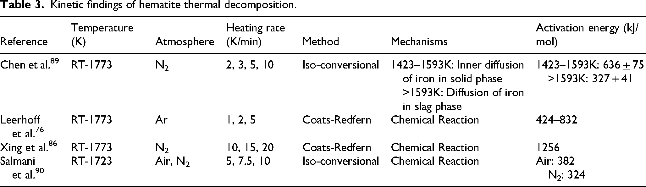
To determine the decomposition temperature of hematite in the ores in practice, TGA (thermogravimetric analysis) measurements have been widely used in the literature. Chen et al. 89 reported that the hematite within a low-grade ore decomposes via a two stage process; the first stage occurs between 1423 and 1593 K, while the second stage takes place at temperatures above 1593 K. Similarly, Qu et al. 85 determined the thermal decomposition temperature of hematite in higher grade ores (94.94 wt.% Fe2O3) to be between 1473 and 1573 K. Leerhoff et al. 76 studied the decomposition behaviour of varying low-grade iron ores and also identified a two stage process. Depending on the mineralogy and heating rate, the first stage occurred between 1312 and 1419 K, and the second stage at temperatures above 1676 K. However, the influence of mineralogy on the decomposition temperature was only marginal and mainly influenced by the applied heating rate. Xing et al. 86 examined the effect of particle size on the decomposition temperature of hematite ores and observed no significant influence. The decomposition range they reported was between 1480 and 1532 K, depending on the heating rate and particle size. Generally, it is clear that the initiation temperatures of the thermal decomposition determined with the TGA are significantly higher compared to the theoretical thermodynamic calculations shown in Figure 6, indicating kinetic barriers to thermal decomposition.
Several studies76,86,89,90 were carried out to determine the reaction mechanisms of hematite thermal decomposition. The main findings from selected studies are presented in Table 3. These kinetic mechanisms are usually determined under non-isothermal conditions using several heating rates, with kinetic parameters commonly determined via model-free iso-conversional methods, like the Ozawa Flynn and Wall method 91 or the model-fitting Coats-Redfern method. 92 Overall, there seems to be a consensus that the hematite thermal decomposition is controlled by chemical reaction. Only Chen et al. 89 defined different reaction mechanisms, consisting of inner diffusion of iron at the first stage, followed by slag diffusion. The reported activation energy varies significantly across studies. Salmani et al. 90 reported comparably lower values for the main decomposition stage, while Chen et al. 89 observed higher values, particularly in the first stage. Leerhoff et al. 76 found a wide range of activation energies, influenced by ore mineralogy, and Xing et al. 86 reported higher values than those observed in other studies. These trends highlight a strong dependence of the activation energy on the applied method, but also on material properties.
Kinetic findings of hematite thermal decomposition.
Gas reduction of iron oxides
During the pre-reduction stage of smelting reduction and DRI processes, iron ores are reduced via gas–solid reactions with H2 and/or CO. Below 843 K, only hematite and magnetite are stable, and reduction proceeds in two steps via the disproportionation reactions (5.5, 5.6, 5.9, 5.10), producing magnetite and metallic iron. Above 843 K, wustite becomes more thermodynamically stable, and the reduction shifts to a three-step process involving wustite. This temperature marks the threshold for a change in the dominant reduction pathway.6,93 The chemical reactions of iron oxides with H2 and CO are presented in Table 4 (reaction 5.5)–(reaction 5.12) with their reaction enthalpy given at room temperature (25 ˚C)94,95:
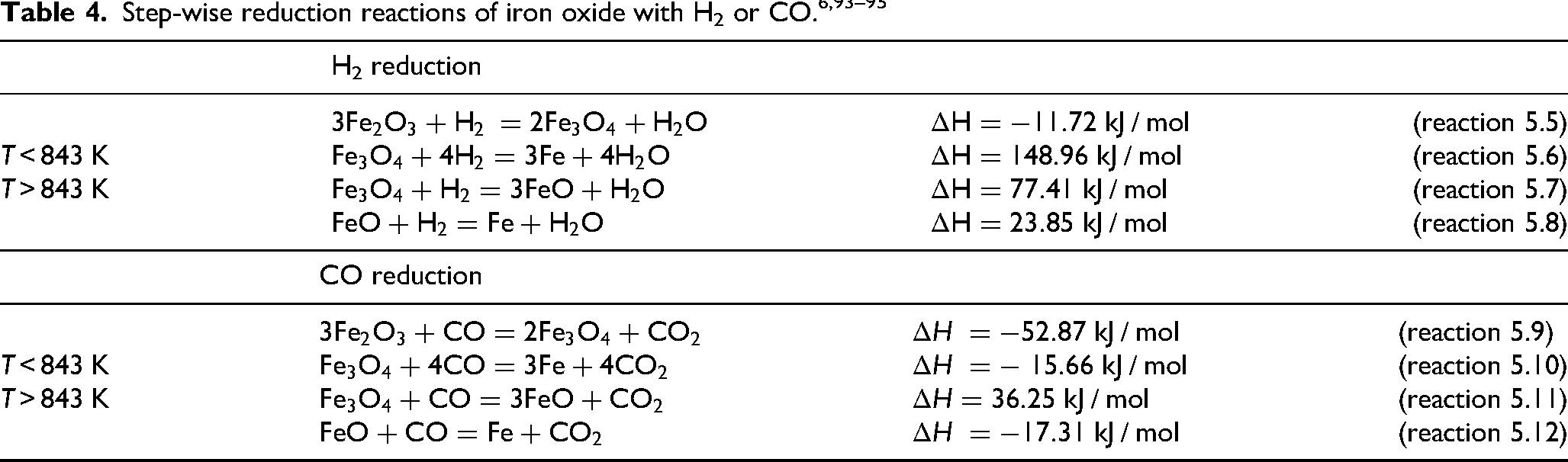
Examining H2-based reductions (reaction 5.5)–(reaction 5.8), only the reduction from hematite to magnetite is exothermic. The following steps of the reduction are endothermic. This indicates that additional energy has to be supplied to the system after the pre-reduction of hematite to magnetite. For CO-based reduction, the reduction of magnetite to wustite is endothermic. All other reduction steps of the iron oxides are exothermic and, therefore, release energy to the system. Hence, CO reduction has a better influence on the overall energy balance of the system.
Figure 7(a) represents the classic Bauer-Glaessner diagram, where the influence of the reducing gas partial pressure is displayed for the ratio of CO to the total gas volume of CO + CO2 and similar for the case of H2 and H2O. The main takeaway from the diagram is that CO is a better reducing agent at lower temperatures, while H2 is preferred at higher temperatures, from a thermodynamic perspective. This indicates that under the DRI conditions, H2 is better suited as the reducing agent. Figure 7(b) shows a broader temperature range, which is more relevant for the suspension smelting processes. The gas composition displays the post-combustion ratio, present in the cyclone converter of the HIsarna furnace (equation 4.1) and, therefore, considers the presence of both reducing gases H2 and CO and the resulting gases H2O and CO2. A pre-reduction degree of 33.33% would indicate the reduction from hematite to wustite. 85 Therefore, the figure highlights that wustite is the thermodynamic limit of pre-reduction in the HIsarna furnace, where a decrease in the PCR would increase the pre-reduction degree (PRD). During the flash ironmaking, which operates at higher amounts of reducing gases, the reduction to metallic iron in solid and liquid form is theoretically possible.
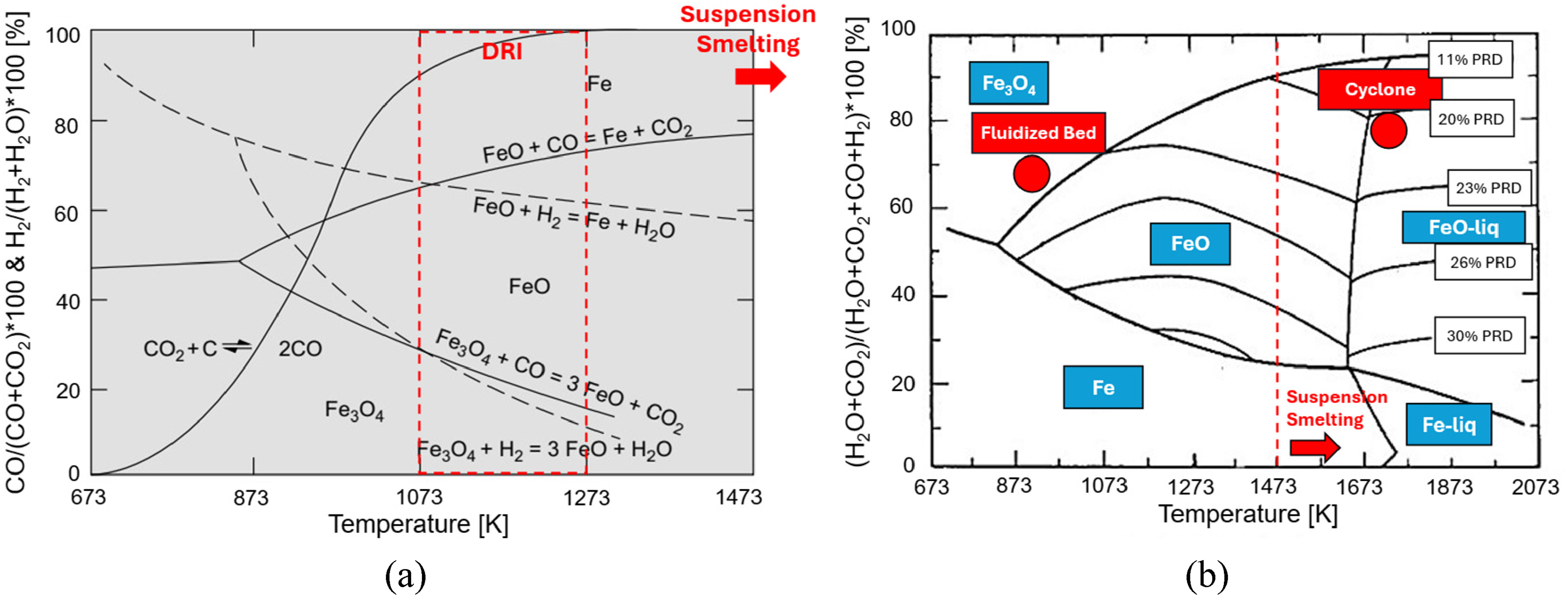
Bauer–Glaessner Diagram for (a) the general reduction of hematite with CO and H2, adapted from 14 with permission from Elsevier and (b) the Bauer-Glaessner diagram with special focus on the conditions during the cyclone pre-reduction in HIsarna ironmaking, adapted from 39 with permission from Springer Nature.
Reaction kinetics of hematite reduction with H2 and/or CO
Spreitzer et al. 96 and Heidari et al. 97 summarised multiple parameters that influence the reduction kinetics of iron oxides and therefore their reduction rate. These parameters can be categorised into process parameters (such as temperature, pressure and gas composition) and material properties (such as particle size, morphology and porosity). Comparing differences between suspension smelting and DRI ironmaking processes, most interesting parameters to consider are the influence of the processing temperatures, material properties like particle size and mineralogy and of course the reducing gas composition. From a kinetic point of view, another important processing parameter is the reduction time. Thermodynamics indicate that reduction of iron ores is already possible at lower temperatures, but the significantly higher temperatures in suspension smelting processes have the potential of decreasing the reduction time.
A general approach to describe the kinetics of the gas–solid reduction of pellets or particles is the (un-)reacted shrinking core model.98,99 In the shrinking core model, the first reactions take place at the outer surface of the particle. The reaction zone then progresses inward towards the core, while the reducing agents CO and H2 diffuse through the developing product layer and towards the unreacted core. The product layer is the already converted material phase surrounding the unreacted solid iron ore core. The developing reduction products (CO2 and H2O) diffuse back through the product layer and into the gas film.
99
The shrinking core model considers interfacial chemical reactions, internal diffusion or a mixed mechanism of both as possible reaction mechanisms.99–102 Generally, chemical reaction-controlled mechanisms are much more temperature dependent than diffusion-controlled mechanisms. Therefore, chemical reaction is often the rate-limiting step at lower temperatures, whereas diffusion becomes more likely to be rate-controlling at higher temperatures.
96
One disadvantage of the shrinking core model is that it assumes a reduction from the outside to the inside of the particle, disregarding the possibility of (internal) nucleation and growth being the underlying mechanism. Based on the selected model, the reaction rate constant can be determined using the Arrhenius equation (equation 5.1).
103
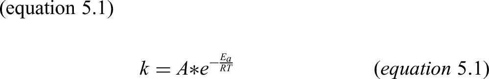
where A is the collision factor (1/s), Ea is the activation energy (J/mol), R is the ideal gas constant (J/(mol*K) and T is the temperature (K). The influence of temperature on the reduction kinetics is generally described by its exponential dependency on the rate constant indicating an increase of the reaction rate with increasing temperature, 97 which is highly beneficial for the suspension smelting processes. A lot of research has been done on the reduction kinetics of iron ore pellets and fines with H2 and CO, and a selection of studies focusing on the reduction under isothermal conditions are summarised in Table 5. In terms of kinetic aspects of the gas reduction, it is important to evaluate the influence of H2 and CO on the reaction rate, the underlying reaction mechanism and the arising activation energy.
Overview of isothermal kinetic studies on H2–CO reduction in ironmaking.
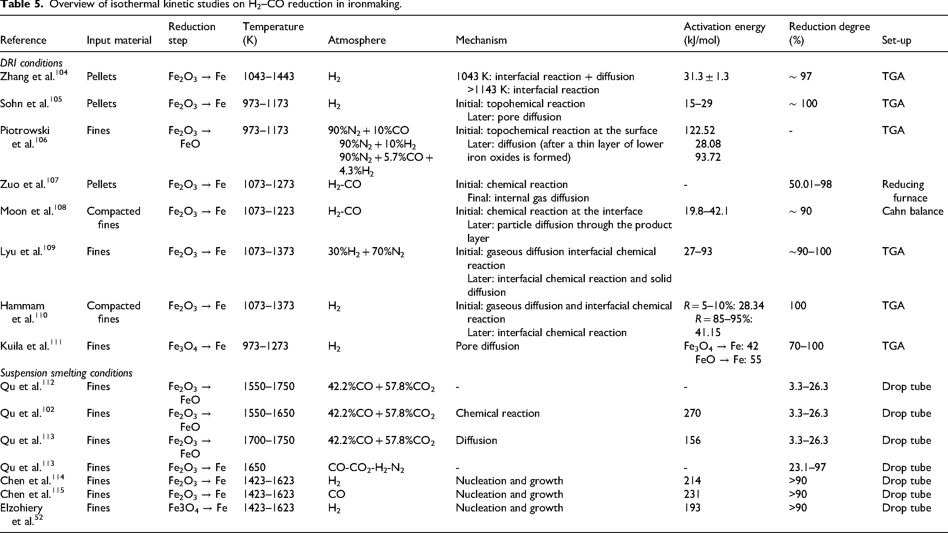
Literature reports that the presence of hydrogen gas in the reducing atmosphere offers an advantage over carbon monoxide, due to increased reduction rates.107,108,116 This is generally attributed to the faster diffusion of hydrogen due to its smaller molecular size and lower viscosity. 107 Regarding the reaction mechanism of H2 or CO reduction, literature indicates a change in the reaction mechanism throughout the reduction process from hematite to metallic iron. Sohn et al. 105 investigated hematite pellet reduction in pure H2 at 973–1173 K and found a transition from a topochemical reaction in the early stages to pore diffusion in later stages. Similar observations were reported by other studies,106–108 explained by the formation of an initial iron or wustite layer on the surface, limiting the gas diffusion through the product layer. However, some authors propose slightly different mechanisms. Kuila et al. 111 studied the reduction of magnetite fines with H2 at temperatures between 973 and 1273 K and found that both the reduction from Fe3O4 to FeO and the subsequent reduction from FeO to Fe is controlled by pore diffusion. Lyu et al. 109 used a mixture of 30% H2 and 70% N2 for the reduction of hematite fines and proposed that the first stage of the reduction is already a mixed mechanism of gaseous diffusion and chemical reaction at the interface, before it shifts to the mixed mechanism of interfacial chemical reaction and solid diffusion.
The influence of H2 and CO on the activation energy was investigated by Piotrowski et al. 106 The reduction of hematite to wustite was investigated for temperatures between 973 and 1173 K in reducing gas mixtures of H2, CO and N2. The calculated activation energies varied between 25 and 125 kJ/mol, depending on the gas composition. For the reduction with pure hydrogen, significantly lower activation energies (ΔEa = 28.08 kJ/mol) are determined in comparison to CO-based gas mixtures (ΔEa = 122.52 kJ/mol). For the mixture of the two gases, an activation energy of ΔEa = 93.72 kJ/mol was determined. Conversely, Moon et al. 108 observed an increasing activation energy with an increasing amount of H2 in the atmosphere.
The influence of particle size on the reduction rate of hematite fines in H2 atmosphere has been investigated by Hou et al. 117 (pure Fe2O3), Wagner et al. 118 (pure Fe2O3) and Pang et al. 119 (62.7 wt.-% T.Fe, Fe2O3 + Fe3O4). All observed a general increase in reaction rate with decreasing particle size. Hou et al. 117 found 0.045 mm as the lower limit of the influence because the internal diffusion resistance doesn’t have an influence on the overall reduction rates at these dimensions. Pang et al. 119 further state a co-dependency of the temperature and particle size. The influence of temperature on the reduction is stronger with decreasing particle sizes.
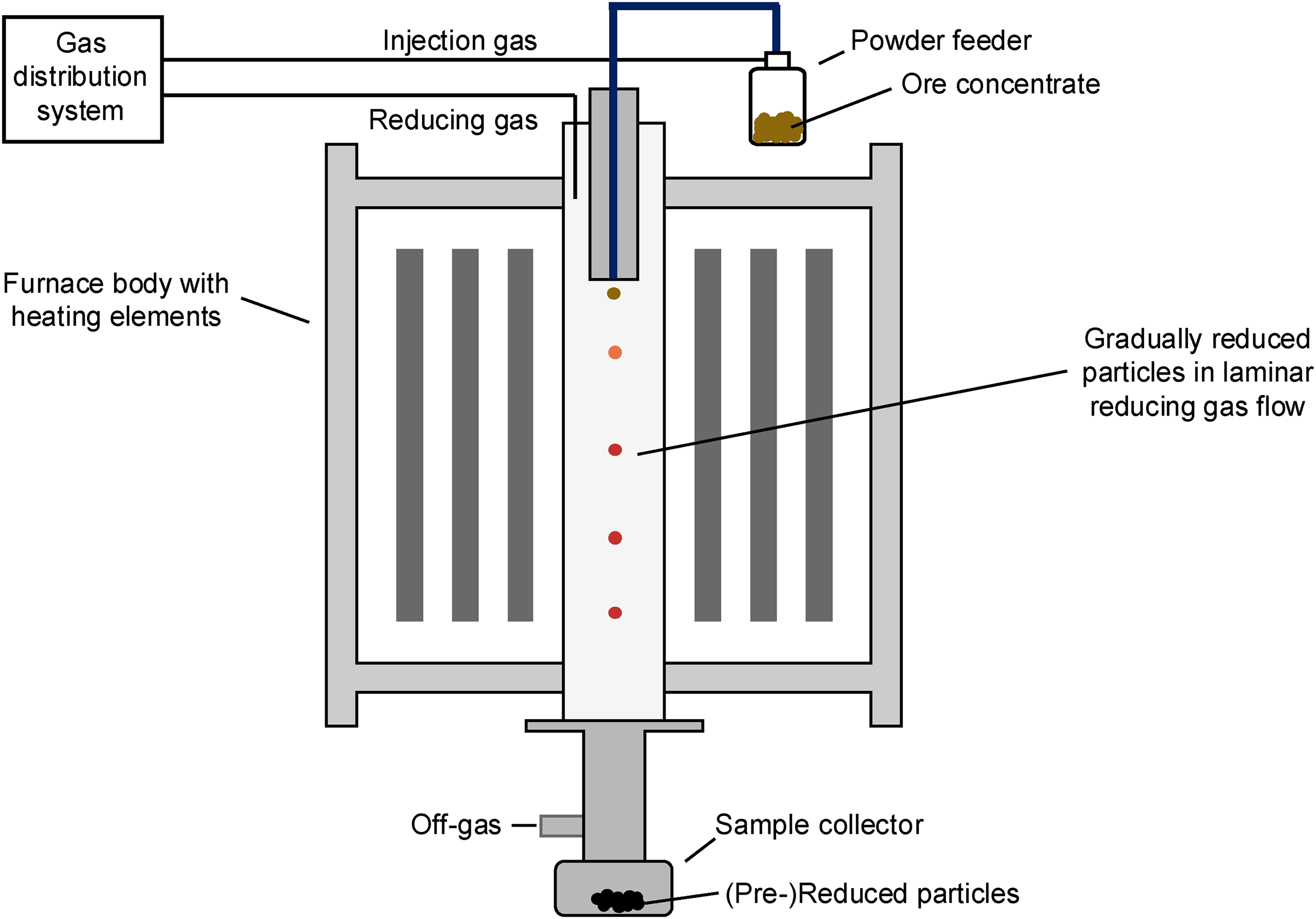
Even though a significant reduction with H2 is already achieved at lower DRI processing temperatures, the advantage of higher temperatures is the acceleration of the reaction and, therefore, decrease in the needed reduction time for the pre-reduction under industrial process conditions relevant to HIsarna and Flash Ironmaking Technology. In contrast to DRI ironmaking, thermal decomposition of the hematite ore becomes a crucial part of the process. Considering the reduction of iron ore fines at elevated temperatures, significant research was conducted at Delft University of Technology95,102,112,113,120–122 in the framework of investigating fine ore reduction in the pre-reduction section of HIsarna and at the University of Utah16,43,44,52 for Flash Ironmaking. Both approaches focus on a fast reduction at high temperatures. A common experimental apparatus used in these studies is the drop tube furnace, where the ore concentrates are transported through a defined reaction zone filled with the reducing gases present in laminar flow. The rough principle of a laminar flow reactor as it is used in the studies at Delft University of Technology and the University of Utah is portrayed in Figure 8. The particles are generally introduced into the hot reaction zone via a pneumatic powder feeder, with the powders being carried with an injected gas stream into the furnace, where they are gradually reduced via the laminar reducing gas flow. Next, the reduced particles are quenched to prevent reoxidation and collected at the bottom using a sample collector.52,95,114
Qu et al.102,112,113 studied the impact of gas reduction mechanisms on the overall reduction of fine hematite ores at short particle residence times (210–2020 ms). They investigated the reaction kinetics for a gas mixture containing 42.2% CO and 57.8% CO2, and found that the reduction was chemical reaction-controlled in the temperature range of 1550–1650 K, with an activation energy of 270 kJ/mol. With an increase in temperature (1700–1750 K), the reaction mechanisms shifted to diffusion and the activation energy decreased to 156 kJ/mol. They also found a significant influence of the temperature, with only 3.3% of reduction degree at 1550 K and a particle residence time of 210 ms and an increase to 26.3% at 1750 K and a residence time of 970 ms. Based on their observations, they were able to explain the influence of thermal decomposition and gas reduction on the pre-reduction degree in the drop tube furnace. 112 The results are summarised in Figure 9. Until 1700 K, thermal decomposition is the dominant reduction mechanism, with a particularly low contribution of gas reduction at lower temperatures. Gas reduction becomes the significant reduction mechanism at 1750 K. However, the influence of thermal decomposition is only significant in the first 210 ms of the reaction. Since thermal decomposition is mostly completed in this fast timeframe, gas reduction becomes more influential at increasing particle residence times.
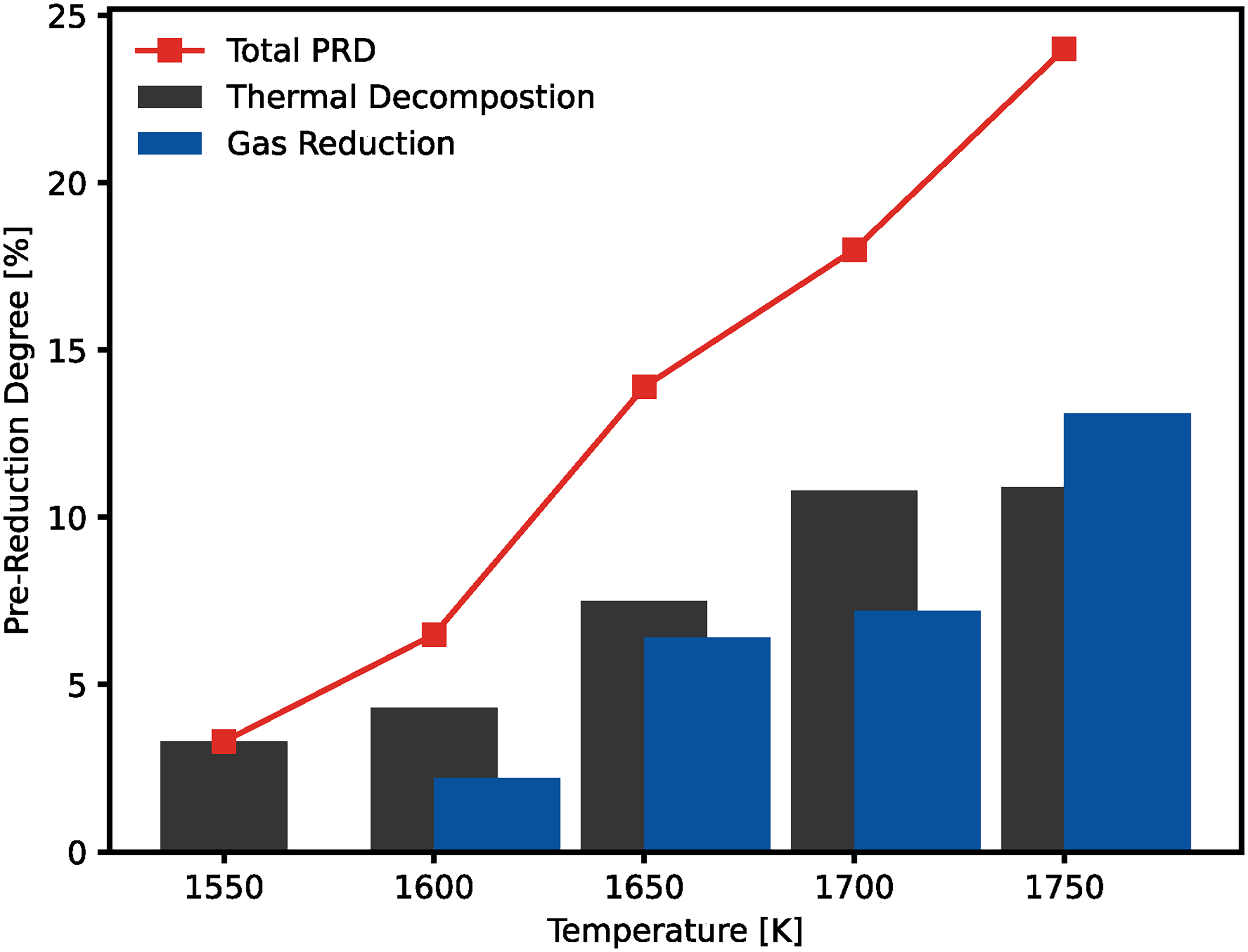
Influence of gas reduction (42.2% CO + 57.8% CO2) and thermal decomposition (100% CO2) on the pre-reduction degree at a particle residence time of 210 ms and a particle size of 45–53 μm, adapted from 112 with permission from ISIJ.
Additionally, Qu et al. 113 studied the impact of hydrogen enrichment on the reduction degree in the drop tube furnace by testing 5 different atmospheres at 1650 K and a relatively long particle residence time of 2020 ms. They showed that by changing the atmosphere from 25% CO and 75% N2 to 25% H2 and 75% N2, the reduction degree increased from 26.4% to 77.1%. Moreover, increasing the hydrogen content in the atmosphere to 75%, the reduction degree increased further to 97%, even at the short particle residence times.
The influence of the reducing gas atmosphere in suspension smelting processes was further studied by Chen et al.114,115 in the framework of developing the flash ironmaking technology. They studied the reduction of hematite concentrates (d = 21 μm) in a temperature range of 1423 to 1623 K in H2 and CO separately. Both H2 and CO reduction followed nucleation and growth as reduction mechanisms and achieved reduction degrees above 90%. However, they observed faster reduction with H2, achieving a similar amount of reduction in 3 s, as it took 5 s for the CO reduction. Building on the reduction of hematite concentrates, Elzohiery et al. 52 tested the H2 reduction of magnetite concentrates (d = 20–25, 32–38, 45–53 μm). Again, they found that the reaction completed within seconds, whereas the duration of the reduction was influenced by the temperature and particle size. All three studies determined nucleation and growth as the governing reaction mechanism, and reported the lowest activation energy for the reduction of the magnetite concentrates (193 kJ/mol), followed by the reduction of hematite concentrates with H2 (214 kJ/mol) and CO (231 kJ/mol), respectively.
Qu et al. 123 investigated the impact of temperature and reduction degree on particle morphology during flash reduction (Figure 10). In the temperature range of 1450–1600 K, with corresponding reduction degrees of approximately 9.6–47.5%, the particles maintained their irregular shape. Under these temperatures, the reaction occurs as gas–solid reduction. However, at temperatures exceeding 1600 K and a reduction degree of 52.2%, the reduction mechanism transitioned to a gas–liquid reduction, leading to the formation of spherical particles, with melting mostly driven by the developing wustite phase. Initially, iron products disperse across the wustite particle before changing into a spherical form as the temperature increases.
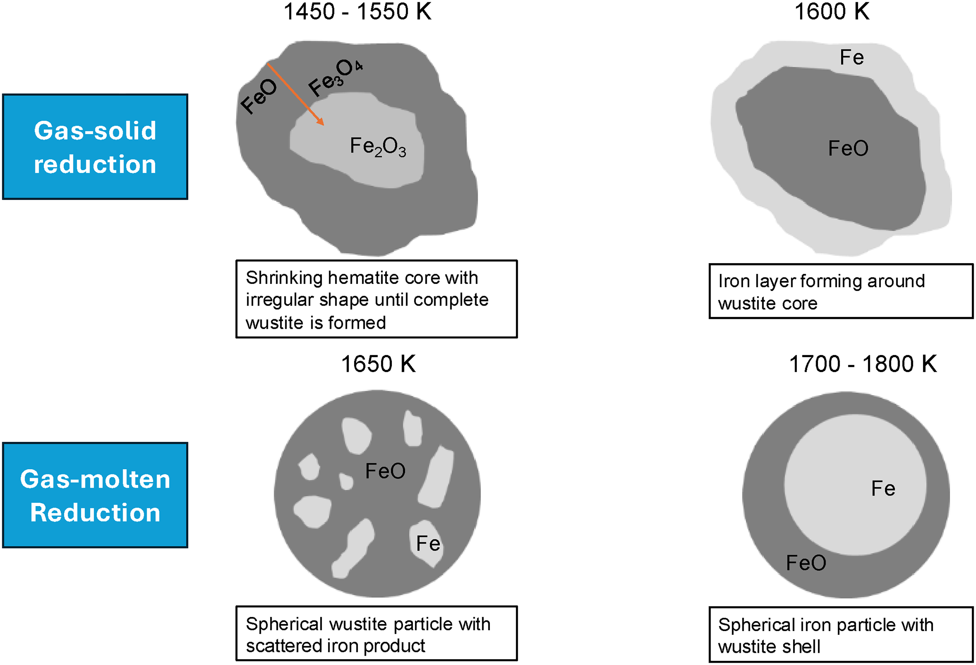
Influence of temperature on hematite particle during gas reduction in a drop tube furnace, adapted from 123 with permission from Elsevier.
The particle size plays a crucial role in the reduction process in suspension smelting. Here again, Qu et al. 112 investigated the influence of particle size on the reduction behaviour of iron ores at high temperatures (1650 K). They studied four particle size fractions (38–45, 45–53, 53–75 and 75–90 µm) in gas atmospheres consisting of CO–CO2 and CO–CO2–H2–N2 and varying contents of reducing gases. For all the tested gas compositions, the reduction degree increases approximately linearly with decreasing particle size. Chen et al.120,121 found an influence of the particle size on the reaction rate constant for the reduction of hematite, described by a nucleation and growth mechanism of magnetite grains, within the hematite particle. The reaction rate constant increased with an increase in particle size from 67 to 85 μm. However, after a threshold of 85 μm, the reaction rate constant decreased with a further increase in particle size. An increase in particle size, however, can yield a negative influence on the heating of the particle, which has a significant influence on the thermal decomposition at the short particle residence times during suspension smelting and therefore leads to a negative effect on the reduction degree. 120
When comparing the reaction kinetics of suspension smelting studies to those of DRI-based ironmaking, a key difference is the substantially higher activation energy observed in suspension smelting. This increased energy requirement is attributed to the high degrees of reduction achieved within very short reduction times. The higher activation energy is therefore higher in suspension smelting processes. However, its significant advantage is the rapid reduction, which enables the formation of metallic iron under the appropriate atmospheric and temperature conditions.
Water–gas shift reaction
The reduction of iron ores with H2 and CO produces H2O and CO2 as combustion products, both of which can participate in the water–gas shift reaction (WGSR) (reaction 5.13), wherein steam (water vapour) reacts with carbon monoxide to form carbon dioxide and hydrogen gas.
124
This reaction plays an important role in influencing the local gas composition during reduction, potentially enhancing the availability of H₂ and thereby affecting the overall reduction kinetics.
The reaction (5.13) is exothermic and reversible.
124
An important factor for the evaluation of the WGSR is its equilibrium constant, KP, which is defined by equation (5.2):
with Pi being the partial pressure of the different gaseous species. While pressure does not affect the equilibrium due to constant mol numbers,
124
it can increase the reaction rate and CO conversion before the equilibrium is reached. If large amounts of steam are present (H2O/CO > 1), the equilibrium shifts towards product formation, increasing CO conversion.
125
Temperature strongly affects the WGSR via the equilibrium constant KP, given in (equation 5.3) (best applicable: 588 to 753 K).124,125
Figure 11 compares KP values calculated via the Reactions Module in FactSage 7.0 126 and (equation 5.3) across 298–1800 K. Both show decreasing KP with rising temperature, indicating that the forward reaction is favoured at lower temperatures. A brief plateau appears in the FactSage calculations at low temperatures but is negligible for high-temperature ironmaking. At ∼1058 K (equation 5.3) and 1101 K (FactSage), KP becomes negative, favouring CO and H2O formation. This shift is crucial in suspension smelting as it may lead to more endothermic conditions, requiring an external energy supply.6,127
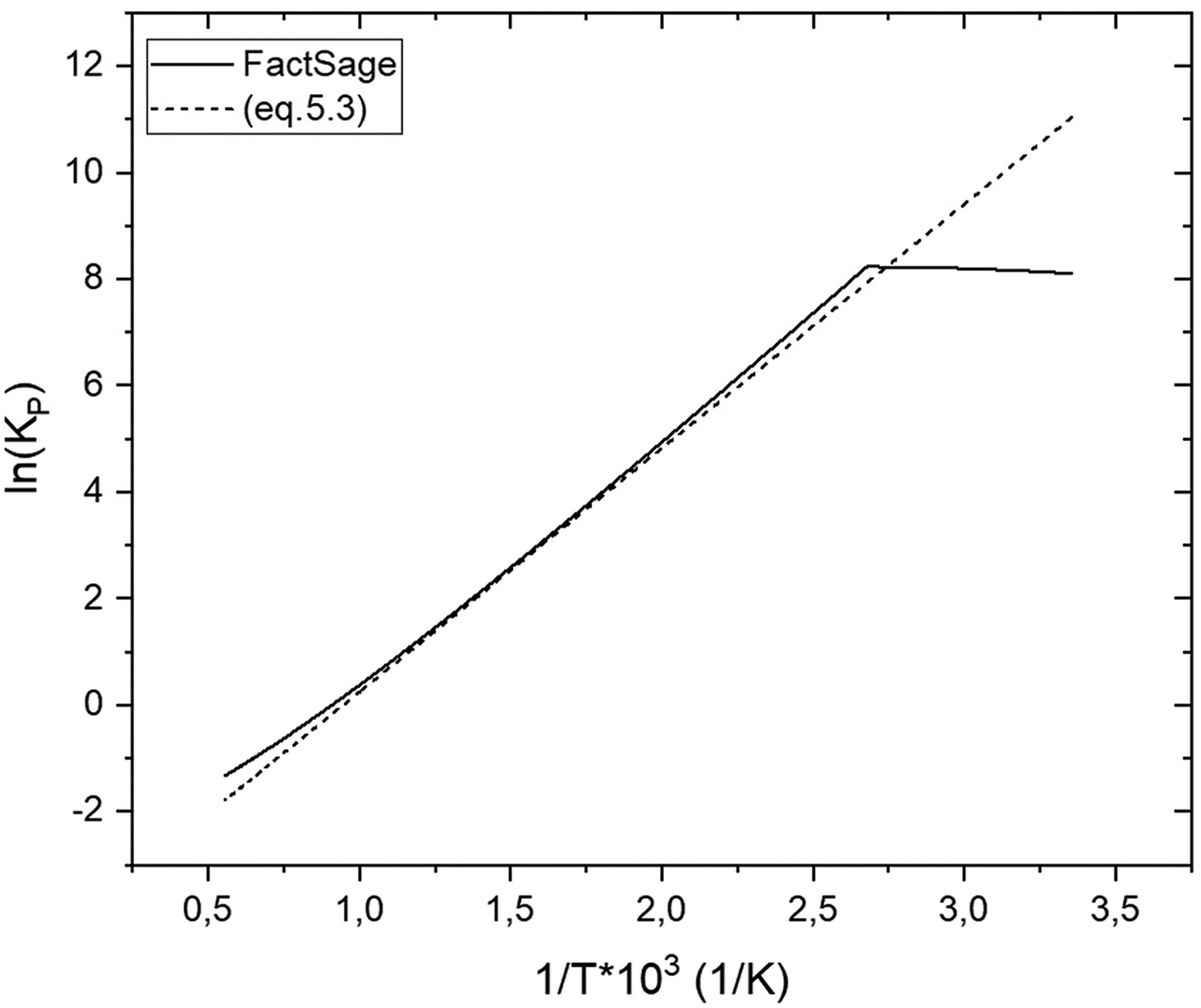
Temperature dependence of WGSR after FactSage7.0 126 calculations and (equation 5.3).
Another issue with the WGSR at high temperatures is the development of water–vapour. Water vapour decreases the thermodynamic driving force for the reduction of the iron oxides. In addition, the water vapour can be absorbed at the reaction interfaces and thus block the reactive surfaces and inhibit reduction. 96 Abdelrahim et al. 128 studied iron ore reduction using CO–CO2–H2–H2O–N2 gas mixtures. They found that when the H2O content exceeds 2% at 1073–1173 K, the reduction efficiency decreases. This was explained by H2O blocking the active sites on the wustite. Lorente et al. 129 observed that up to 5% steam has little effect on Fe2O3 to Fe3O4 reduction but significantly limits the Fe3O4 to Fe step. Similarly, Kim et al. 130 studied magnetite reduction in H2–H2O mixtures (pH2O = 0.1 atm) and observed that H2O negatively affects the reduction rate, particularly at temperatures between 773 and 973 K. However, the influence diminished at higher temperatures.
The influence of the WGSR reaction becomes increasingly interesting due to the intense use of H2–CO mixtures and high temperatures in flash ironmaking processes. If H2O and CO2 are present in the system, the occurrence of the WGSR is possible. From Figure 11, the equilibrium constant is smaller than one around 1100 K, meaning that at this temperature, the H2/CO ratio decreases as CO formation is favoured. Gas-based DRI processes operate at these high temperatures. The MIDREX process, for example, operates with a gas feeding temperature around 1173–1223 K. 5 Particularly in the temperature range relevant to suspension smelting ironmaking processes, where the equilibrium strongly favours the formation of H2O and CO, it is essential to verify the actual composition of reducing gases and assess if the WGSR could reduce the available H2 content. This can become an issue for processes like the cyclone converter of the HIsarna furnace, where large amounts of CO2 are present in the atmosphere, together with H2. Figure 12 shows the influence of the WGSR on a potential gas atmosphere for PCR ∼ 60% for two cases: one based on plant data from literature 63 and another from a theoretical calculation assuming a potential increase in H2 content in the CCF, both calculated with the Equilib module of FactSage 7.0 87 and the FactPS database. 88
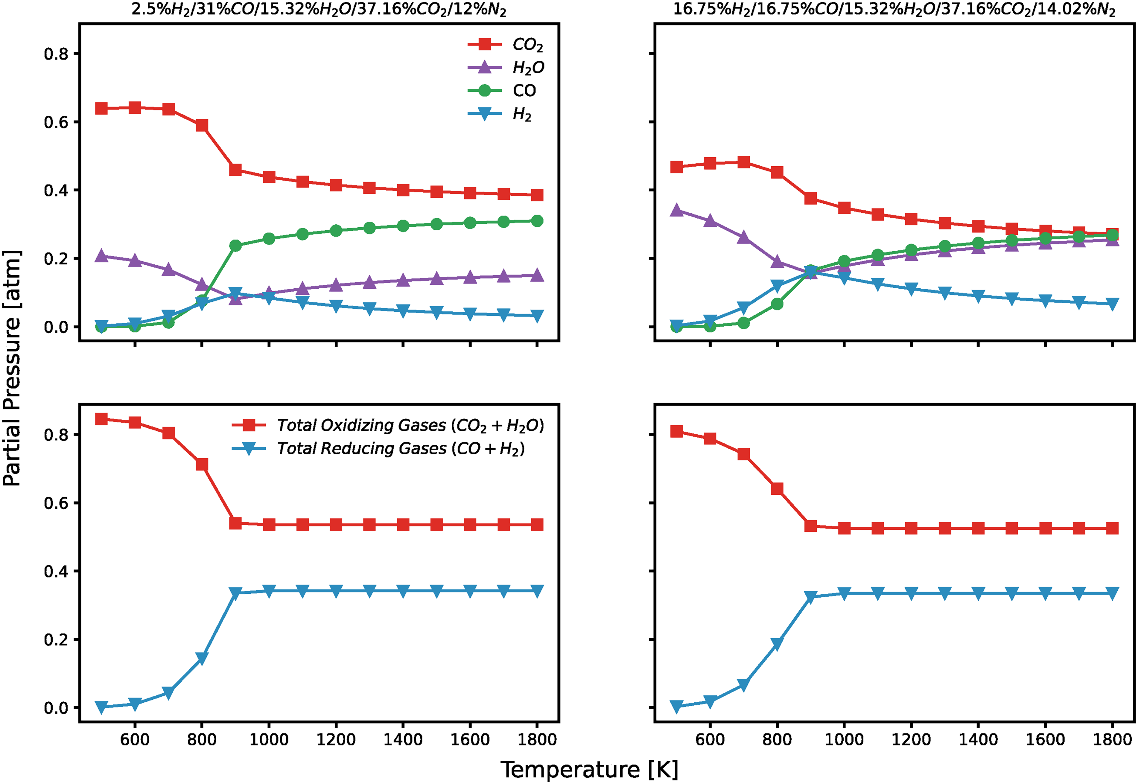
Influence of WGSR reaction of PCR ∼ 60% atmospheres in HIsarna CCF based on plant data 63 and a potential H2-enriched scenario.
In both cases, the equilibrium shifts towards CO and H2O with increasing temperatures, leading to lower amounts of H2 in the reducing gas atmosphere. At high temperatures, the total concentration of reducing and oxidising gases saturates, indicating that although the overall amount of reducing gases remains constant, the proportion of H2 decreases. This shift could lead to a significant decline in the reduction potential of the gas mixture, which is especially crucial in the smelting reduction process where the reactions occur in a very short time.
Conclusion
The transition of the steel industry towards a more sustainable production is becoming an urgent necessity to reduce emissions and comply with the EU climate goals. Currently, the blast furnace is still the dominant technology for ironmaking, but this will change soon. New approaches with either less limitations in terms of input material or more sustainable reducing agents are being developed. In this framework, the adaptation of hydrogen in DRI processes, especially shaft furnace-based, seems to be most promising. In the current state of the art, hydrogen is already utilised in DRI ironmaking, where the transition to high hydrogen concentrations and consequently, a significant reduction in CO2-emissions appears to be most feasible. Compared to the more established DRI ironmaking processes, this article focuses on suspension smelting technologies as a potential alternative, which are currently still under development, including the FIT and the pre-reduction stage of the HIsarna process. The FIT and HIsarna both bring an advantage by eliminating material pre-treatment steps, since fine ores can be directly used without agglomeration. The objective of this review is to understand the reaction mechanisms involved in suspension smelting ironmaking processes, examine how they differ from the more conventional DRI routes and evaluate the role of hydrogen within these processes.
According to the literature, the two primary reaction mechanisms in suspension smelting are thermal decomposition and gas–solid reduction, with a transition to gas-melt reduction at elevated temperatures. Regarding thermal decomposition, an important parameter is the nature of the iron ore. In the case of goethite being present in the ore, its conversion to hematite can influence the material properties due to volume expansion and cracking. This can potentially accelerate the gas-reduction, for example due to the change in particle size and potential reactive surfaces. The thermal decomposition of the hematite phase is mostly described by the reduction to magnetite and has a stronger influence on the reduction during the first 210 ms of suspension smelting. Most literature agrees that the thermal decomposition of hematite to magnetite is chemical reaction-controlled. The kinetic onset of thermal decomposition was determined to lie between 1312 and 1480 K, making it an insignificant mechanism in DRI ironmaking.
From a thermodynamic perspective, reduction with H2 has the disadvantage of being largely endothermic, in contrast to the typically exothermic reduction with CO. This results in a less favourable energy balance and the need to apply additional energy input to sustain the process. In terms of thermodynamic preference, the reduction with CO is favoured at lower, while H2 becomes advantageous at higher temperatures. However, more critical than thermodynamics is the impact of H2 on the reduction kinetics. Overall, H2 enables higher reduction rates compared to CO, which is explained by its better diffusivity. While various parameters influence the reaction mechanism, many studies report a mixed-controlled mechanism. The process is first controlled by chemical reaction at the pellet or particle interface and subsequently transitioned to diffusion control as a product layer of wustite or iron is formed.
The most commonly used equipment to study the kinetics of suspension smelting processes is a laminar flow drop tube furnace, which allows for studying the in-flight flash reduction of the particles under isothermal conditions without the influence of turbulence. In suspension smelting, the particles are reduced within seconds. In this rapid process, the kinetic advantage of H2 becomes particularly relevant for achieving high reduction degrees in a very short residence time. A significant difference from DRI is the higher activation energy observed for suspension smelting, attributed to the fast reduction kinetics. In processes such as HIsarna, achieving high reduction degrees in the pre-reduction cyclone could further improve the environmental performance by reducing the amount of carbon needed for the final reduction in the smelting section. One important consideration during reduction with CO or H2 is the influence of the WGSR in the presence of CO2 or H2O in the gas phase. At elevated temperatures, the equilibrium of the WGSR shifts towards greater production of CO and H2O, which can lower the effective H2 content in the atmosphere and diminish its kinetic advantage. Furthermore, the presence of excessive water–vapour in the system may further negatively affect the reduction performance.
In conclusion, the suspension smelting reduction process remains a relatively new technology compared to the more established DRI processes. Further research is essential to understand how material properties and gas atmosphere influence the reduction kinetics. Nevertheless, hydrogen-enriched atmospheres must be applied with caution, particularly due to the possible limitations imposed by the water–gas shift reaction at high temperatures and the endothermic nature of the hydrogen reduction.
Footnotes
Ethical considerations
There are no human participants in this article, and informed consent is not required.
Consent to participate
Not applicable.
Authorship contribution statement
Philipp Leerhoff: writing – review and editing, writing – original draft, visualisation, validation, software, methodology, investigation, formal analysis, data curation, conceptualization. Christiaan Zeilstra: writing – review and editing, supervision, resources, project administration, funding acquisition. Koen Meijer: writing – review and editing, supervision. Jan van der Stel: writing – review and editing, supervision. Shoshan T. Abrahami: writing – review and editing, supervision. Neslihan Dogan: writing – review and editing, supervision. Yongxiang Yang: writing – review and editing, supervision, resources, project administration, funding acquisition.
Funding
Declaration of conflicting interests
The authors declared no potential conflicts of interest with respect to the research, authorship, and/or publication of this article.
Data availability statement
Data will be made available on request.