
Abstract
This article presents an orepass geotechnical rating evaluator (OGRE) developed to help geotechnical and mine engineers assess the geotechnical risks of proposed orepass locations. Orepasses (near-vertical excavations that transport ore by gravity) are integral to many underground stope mining methods that rely on centralized haulage levels. Despite their importance, orepass designs are often not finalized during planning stages, and their longevity can be compromised by geotechnical conditions. The evaluation method presented is adapted from an existing orepass longevity calculator. Operational considerations, such as material size, blasting practices, cushion guidelines, and support or liner use, were removed, while new geotechnical parameters (sulfide-generating potential, orientation of finger raises, intersection angle of finger raises, and rock quality clarifications) were incorporated based on insights gathered from a survey on orepass planning, design, and construction practices in Canada and the United States. This allows the OGRE to consider stress regime, rock quality, geological structures, sulfide-generating potential, orepass orientation, and finger raise or knuckle use. The resulting tool enables comparison of orepass location options based on geotechnical risk. The value of each of the six aforementioned parameters individually ranges from as low as 0.05 up to 1.00, and they are multiplied together to produce a final rating between approximately 0 and 1. If an orepass location option has a number closer to 1.00, it would indicate less geotechnical risk. Furthermore, this article also identifies methods of managing geotechnical risk through design modifications for orepass locations identified as high risk.
Introduction
Mine planning involves a complex series of interrelated design decisions that shape the technical, economic, and environmental outcomes of a mining project. Many of these decisions are dictated based upon the deposit characteristics (e.g., deposit depth, orientation, or commodity), while others emerge through trade-off analyses that balance production, cost, and safety. Production volumes often drive the selection of mining method and excavation strategies, which in turn determine whether haulage levels and orepasses are required. Mining methods that commonly require orepasses to achieve desired production include: sublevel open stoping, sublevel caving, cut and fill stoping, and vertical crater retreat (Hartman and Mutmansky, 2002).
Haulage levels are common in multilevel underground mines, especially those with underground crushing capability or shaft haulage systems (Darling, 2023). Located below the production levels, haulage levels serve as key collection points where broken ore is transferred for transport to the surface. In many mines, gravity is harnessed to move material (e.g., ore) from production levels to the haulage level through vertical or near-vertical excavations called orepasses (Darling, 2023).
At the tipping point of an orepass, a sizing device, for example, grizzly, restricts oversize rock that could damage the walls or block the pass. In mines with multiple production levels, secondary connections called finger raises feed material into the main orepass. At the base, where the orepass meets the haulage level, various control structures may be installed (e.g., drawpoints, hoppers, chutes, or knuckles) to regulate flow and reduce impact velocities.
The size and configuration of orepasses depend both on mining method and deposit geometry. In Canada and the United States, orepasses are typically steeper than 80° from horizontal, measure 3 × 3 m (10 × 10 ft) in cross-section, and extend more than 38 m (125 ft) in length (Guerin-Davey and Brickey, 2025; Hadjigeorgiou et al., 2005). However, in deep operations in countries such as Canada, Chile, Indonesia, South Africa, and Sweden, long or ultra-long orepasses may extend 300–700 m (980–2300 ft), demanding specialized design and geotechnical considerations (Salmi et al., 2024a).
Orepasses also vary in lifespan and operating strategy. Operations often utilize multiple orepasses at once, though this is dependent on production demands, mining method, and mine layout. Some remain in service for only a few years, while others last the full life of the mine (Salmi et al., 2024a). They may be operated full, partially full, or empty, depending on material characteristics, stability concerns, and production needs. Operating a pass full can reduce wall wear and provide temporary storage but may also increase the risk of blockages (e.g., hang-ups). Empty orepasses minimize hang-ups within the pass but also expose the system to upstream delays (e.g., blockages in stopes, loading equipment failure) if material cannot be delivered (Skawina et al., 2022). Although orepasses generally function without mechanization, their operation presents several design and management challenges that must be carefully considered during mine planning.
Orepass challenges
The main orepass challenge is wall degradation from either impact damage or wear, as shown in Figure 1. If the tipping point is not aligned with the orepass, the impact zone of the orepass wall can start to deteriorate. Cracks can form, leading to wedge failure near the top of the orepass. Material can also start to bounce from wall to wall, which creates damage zones down the entire length of the orepass. Additionally, the discharge point of finger raises can cause impact damage to the opposite orepass wall. If the orepass is oriented improperly in relation to the strata, wall degradation can be accelerated. Orepass degradation may impact planned production within an operation, as orepasses are relied upon to efficiently transport material from the production to haulage levels.
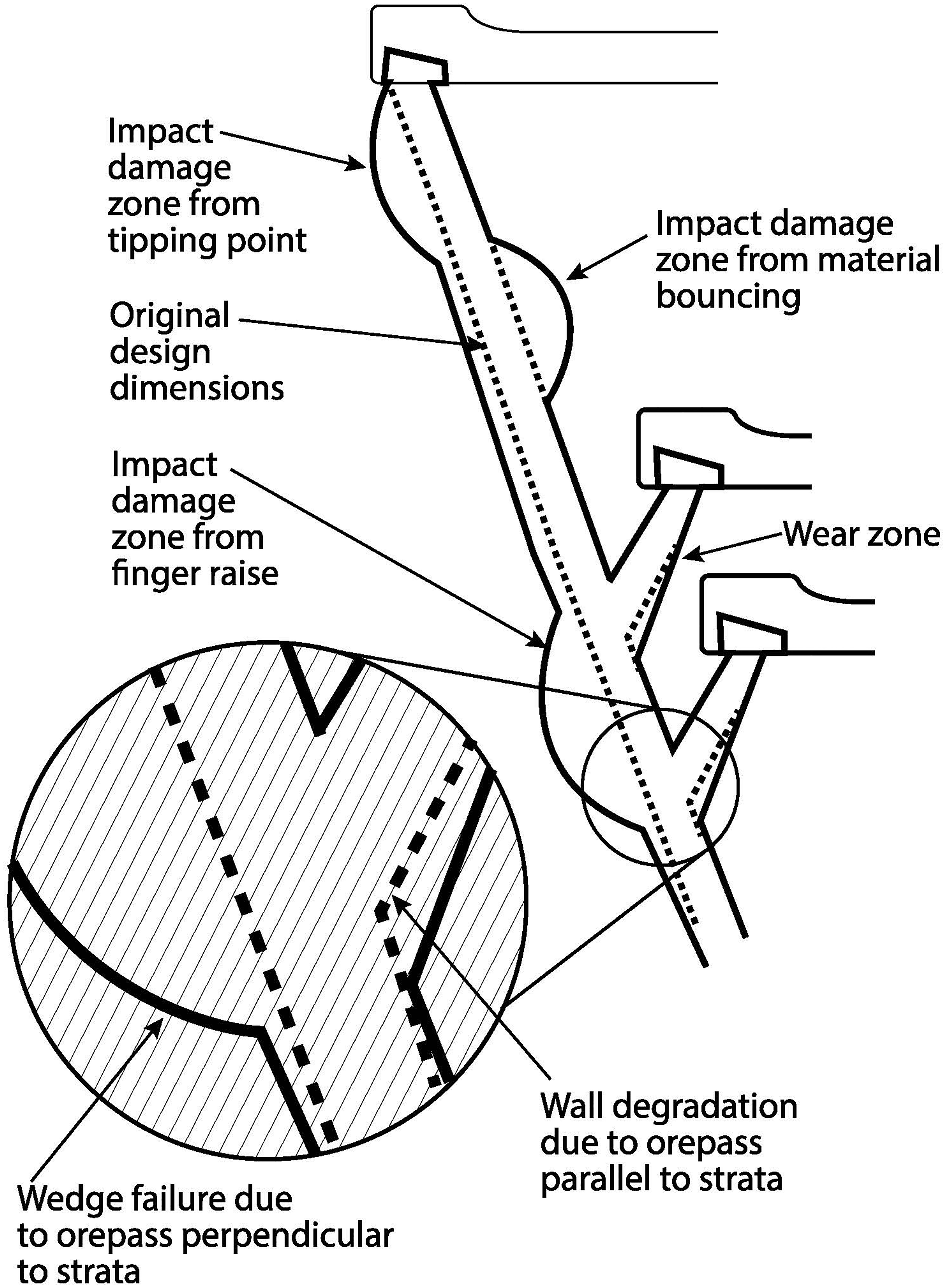
Typical damage seen in an orepass, (i) impact damage at the tipping point (ii) impact damage from material bouncing on the orepass walls (iii) impact damage from the finger raise discharge point (iv) wall degradation from strata (v) wedge failure. Not to scale. Source: Guerin-Davey and Brickey (2025).
Furthermore, there is typically no defined strategy or guideline for orepass design (Hadjigeorgiou and Stacey, 2013), which can lead to mine planners not understanding the potential risks of orepass placement in adverse geotechnical conditions. Hadjigeorgiou and Mercier-Langevin (2008) created the orepass longevity calculator (OLC) to provide a way for mine planning engineers to predict orepass life, measured in millions of tons of throughput. In 2022, the OLC was updated to a longevity chart (LChart) by Sredniawa et al. (2022) based on case study data from the Kiruna Mine, Sweden. For the presented study, the LChart is applied in an adapted form to evaluate the geotechnical risk level of potential orepass sites. By removing the operational parameters of the LChart and modifying or adding additional ground condition parameters, operations can utilize the presented orepass geotechnical rating evaluator (OGRE) to evaluate orepass options during the mine planning phase. The use of the OGRE system will allow operations to understand the risk of placing orepasses in particular locations and provide a novel approach to orepass planning. Subsequent sections outline the technical background information, the OGRE methodology, the case study mine, and the outcomes of applying the OGRE system.
Background
There are many factors that can affect the geotechnical stability of orepasses, which can be divided into three main categories: ground conditions, design parameters, and operational factors. Ground condition factors are properties of the rock or orepass itself, and though they can be somewhat mitigated if the orepass is placed in a different area or angled differently, there is only so much an engineer could do to change them. Design parameters involve understanding the ground conditions and adapting the design to best suit these conditions. Operational conditions are decisions that the operation is in total control of and occur during the mine operation. Altering these practices can not only extend or shorten orepass life expectancy but can also impact the design parameters. A more detailed description of factors in general that impact orepass stability and longevity, as well as how they impact each other, can be found in the article Rock Engineering Systems for Quantifying Risks and Controls for the Resilient Design and Optimisation of Long and Ultra-long Ore Passes (Salmi et al., 2025).
Ground conditions
Ground conditions are properties inherent to the rock mass and cannot be changed. It is important to understand the ground conditions of a given location for mine infrastructure, such as an orepass, to get an idea of the geotechnical risk level of each particular location. The following ground conditions are discussed in relation to orepasses: (i) stress regime, (ii) rock quality, and (iii) major structures.
Stress regime
The stress regime is the ratio of the principal stress, σ1, to the uniaxial (unconfined) compressive strength, σc, of the orepass walls. It is the inverse of the stress reduction factor (Barton et al., 1974). The principal stress, σ1, is the maximum principal stress and is one of the three states of stress necessary to produce rock failure (Mogi, 2007). Uniaxial compressive strength, σc, is determined in a lab by placing a cylindrical rock specimen under an axial load, without any lateral confinement, and loaded until failure (Sivakugan et al., 2013).
Rock quality
The Rock Mass Rating (RMR) system was first developed by Bieniawski in 1973 and modified further by Bieniawski (1989) as more case study data became available. The purpose of this rating system is to classify the geomechanics of the in-situ rock and to provide an estimate of the rock strength, that is, rock quality. The RMR system uses six parameters: (i) Uniaxial compressive strength of the rock, (ii) rock quality designation, (iii) spacing of discontinuities, (iv) condition of discontinuities, (v) groundwater conditions, and (vi) orientation of discontinuities.
Each structural region of the rock mass, usually coinciding with a major structural feature such as a fault, is analyzed and given a rating with a maximum overall score of 100. Ratings are divided into five categories: (i) very good rock (RMR: 81–100), (ii) good rock (RMR: 61–80), (iii) fair rock (RMR: 41–60), (iv) poor rock (RMR: 21–40), and (v) very poor rock (RMR: <20) (Bieniawski, 1989). Bieniawski also provides construction method and support suggestions for each RMR value. The first five parameters contribute positively to the rating, providing between 15 and 30 points each, and the last parameter (orientation of discontinuities) is an adjustment considering how favorable or not the joint orientations are with respect to the project, and ranges from 0 to −60 (Sivakugan et al., 2013). The sum of all six parameters determines what rating category the rock mass is classified as.
Geologic structures
Structures within a rock mass, such as faults or joint sets, can cause potential geotechnical issues when an excavation intersects the structure. Faults are fractures in the strata where significant shear displacement has occurred between adjacent blocks (Sivakugan et al., 2013). Additionally, faults are often surrounded by zones of fracture rock, often called damage zones, which can scale with various fault parameters (Faulkner et al., 2011). Discontinuities create planes of weakness that become the most vulnerable points within an excavation and lead to instability (Sivakugan et al., 2013).
Joint or bedding planes are geological discontinuities and are referred to as sets when they have the same geologic origin, orientation, spacing, and/or mechanical characteristics (Sivakugan et al., 2013). These sets give a plane of potential failure, and if an excavation such as an orepass passes through them at too similar an angle (within 45°), plane or slabbing failures may occur.
Design parameters
Design parameters are aspects of design that can be modified to accommodate the inherent ground conditions yet still have an impact on orepass longevity, stability, and performance. In fact, Salmi et al. (2025) list the orepass construction method and parameters, including orientation, location, and fingers, as one of the eight principal representation factors in optimizing orepasses. There is a risk associated with designing underground excavations, such as orepasses, in line with discontinuities. The following design parameters are discussed: (i) sulfide potential, (ii) orepass orientation, and (iii) finger raise or knuckle use.
Sulfide potential
A major risk of mining through an area that contains sulfides is sulfide oxidation, as heat production is a byproduct of sulfide oxidation. Wet oxidation, dry oxidation, or even combustion can occur as part of sulfide oxidation chemical reactions (Bergholm et al., 1995). The reaction temperatures can be upward of 600°C (1110°F). When this process is looked at within an orepass, these temperatures can cause the material within the pass to heat up as well. This can fuse material in the pass, resulting in a blocked orepass. Clearing these types of blockages is often difficult and may require the use of explosives. Excessive use of explosives to clear orepass blockages can further damage the orepass walls, leading to additional wall degradation (Hadjigeorgiou and Lessard, 2010).
Another concern with sulfide oxidation within orepasses is the production of acid. Some detrimental effects from acid production include concrete degradation, steel corrosion, structural degradation, and accelerated chemical weathering of rock (Bryant, 2003; Salmi et al., 2025). Any of these effects can decrease the stability of the orepass, particularly if support systems or terminal end infrastructure are in use. There can also be potential environmental side effects, such as acid mine drainage.
Orepass orientation
Engineers have limited flexibility to adjust orepass orientation due to safety constraints, required offsets, and tramming distance considerations, but any misalignment between tipping point, the orepass, or the surrounding strata can create significant operational and geotechnical drawbacks. Salmi et al. (2024b) specifically noted alignment relative to geological strata and structures as one of the top parameters identified by experts as an orepass concern. Wedge failures occur when two discontinuity planes intersect (Sivakugan et al., 2013), and these large blocks of material may further damage an orepass or even create a blockage. A wedge failure may occur if the tipping point is not aligned with the orepass, as a zone of impact damage at the top of the orepass can form, leading to cracking. Wedge failure may also occur when cracks form due to impact damage within the orepass walls intersecting the discontinuity plane. One contributing mechanism is the tendency for material to rebound within the orepass when discharged from a misaligned tipping point or when impacting the wall opposite a finger raise.
Finger raise or knuckle use
If an operation has multiple production levels, there may become a need to connect multiple levels to a single orepass. Additional levels will connect to the orepass through the use of a finger raise. The angle between the finger raise and orepass can become problematic, as described in Esmaieli and Hadjigeorgiou (2009), as it can maximize the impact speed of the material coming out of the finger raise and into the opposite orepass wall. There is often damage to the wall opposite the finger raise discharge point, as shown in Figure 1. Using a different angle between the finger raise and orepass can mitigate this issue.
A knuckle is used at some operations at the terminal end of an orepass to slow down material as it exits the orepass. It is a sharp change in direction, similar to a finger knuckle if you bend your finger, but also can lead to pass degradation due to material impacting this area of the orepass (Guerin-Davey and Brickey, 2025). Additionally, the orientation of the knuckle could lead to additional degradation if it is in line with discontinuities.
Operational considerations
Operational considerations of orepasses are factors that can be altered or adjusted to increase the stability of an orepass once it is in operation but can also impact the design. Generally, practices remain consistent across an entire operation and will not change based on which orepass in a given area is selected. The following are major operational decisions that need to be considered during the orepass design phase:
Material size
Material size can be regulated using a material control device, such as a grizzly or scalper. The use of a material control device can reduce the impact damage to orepass walls by both spreading out the material and preventing oversize material from entering the orepass.
Blasting to restore
If an operation uses explosives to clear hang-ups, there is a high likelihood that the orepass walls will be damaged during a detonation. It is important to understand the potential impact of the orepass integrity and utilize other methods to either clear hang-ups or prevent them from occurring.
Cushion guidelines
An orepass can be operated full, partially full, or empty (pass through). If an orepass is operated full, there is less impact damage to the orepass walls as the material speed is greatly reduced, however, material may consolidate within the pass, creating a blockage, or have material start to oxidize and fuse to the orepass walls. It is important to note that if finger raises are utilized and active, the material level cannot be above the lowest finger raise in the orepass or material will not flow.
Support and liners
The use of support and liners can extend an orepasses expected life, if these systems are not maintained, they can deteriorate and contribute to orepass blockages or loss. Salmi et al. (2025) list orepass supporting methods as one of the eight principal representation factors in optimizing orepasses as this specifically affects the stability and integrity of orepasses. Often, geotechnical conditions will dictate the need for the use of support or liners, but they are an additional expense for the operation.
Previous work
In 2008, Hadjigeorgiou and Mercier-Langevin (2008) presented an OLC. In 2022, Sredniawa et al. (2022) published an extension of the work done by Hadjigeorgiou and Mercier-Langevin as an orepass LChart based upon case study data from the Kirunavaara (Kiruna) Mine in Sweden.
Orepass longevity calculator
The OLC was developed by Hadjigeorgiou and Mercier-Langevin (2008) in 2008 to assist operations in understanding the longevity of an orepass through a measure of the amount of material that can be safely transferred through the pass. The orepass longevity, in millions of tons, was calculated as shown in equation (1), where LRF is the longevity reduction factor, and LEF is the longevity extension factor:

The LRF factor was calculated as shown in equation (2) and was based upon both ground conditions and operational factors that reduce the life expectancy of an orepass. The first group of factors is different adverse ground conditions that the orepass can encounter: A1 is for stress regime, A2 is for the RMR, A3 is for major structures, and A4 is for the orientation with respect to major joint set or bedding. The second group of factors is different wall impact factors: B1 is for material size and B2 is for the use of fingers or knuckles. The last group of factors is for orepass operational factors: C1 is for the practice of blasting to remove hang-ups, and C2 is for cushion guidelines:

The LEF factor was calculated, as shown in equation (3), based upon two factors that can extend the life of an orepass if implemented. The first factor, F1, is to implement ground support within the orepass, and the second factor, F2, is to line the orepass:

The OLC was verified with the use of several case studies, and the most critical factor influencing orepass longevity was found to be the rock mass structure as “All other factors being equal, an ore pass situated in very high quality rock is likely to be in operation 20 times longer than an identical ore pass located in poor rock” (Hadjigeorgiou and Mercier-Langevin, 2008). The primary goal to achieve the longest orepass longevity should be placing an orepass in the best ground conditions available.
Longevity chart
In 2022, Luossavaara-Kiirunavaara Aktiebolag Kiirunavaara researchers (Sredniawa et al., 2022) created an orepass LChart as an extension of the OLC Hadjigeorgiou and Mercier-Langevin (2008). The eight included categories in the LChart are: (i) stress regime, (ii) geotechnical conditions (rock quality), (iii) material size, (iv) number of finger or knuckles, (v) blasting hang-ups, (vi) cushion or filling orepass guidelines, (vii) wall support, and (viii) throughput and renovation items. The stress regime, rock quality, and material size categories were modified over the 2008 version, and results were presented from a case study performed at the Kiruna Mine.
The case study was used to create a LChart for each orepass, which showed the maximum throughput (Mtonnes), throughput to date (Mtonnes), and throughput until rehabilitation (Mtonnes). This analysis allowed the operation to schedule renovations and reconcile them with the short-term production plan. Though the LChart did not predict orepass damage, it allowed the operation to schedule which orepass sections (as their orepasses are divided into multiple sections) require rehabilitation and maintenance in the future, and to integrate this into the production schedule.
Orepass geotechnical rating evaluator formulation
The core methodologies of the OLC (Hadjigeorgiou and Mercier-Langevin, 2008) and LChart (Sredniawa et al., 2022) were adapted to evaluate geotechnical risk, resulting in the development of the OGRE. Based off of an online questionnaire survey and follow-up email interviews done on orepass use in Canada and the United States (Guerin-Davey and Brickey, 2025) and results from a 2024 global online survey of orepass subject matter experts (Salmi et al., 2024b), the rock quality, orientation, and finger raise or knuckle use categories were modified and an additional category, sulfide-generating potential, was added. In order to calculate the rating based on the exact location of the orepass, only ground condition categories were applied to the evaluator. The following orepass categories are utilized:
Stress regime (SR) Rock quality (RQ) Sulfide-generating potential (SP) Major structure (MS) Orientation (O) Finger raise or knuckle use (FR)
Operational factors were removed as they were assumed to be constant regardless of where the orepass is placed. For example, if an orepass option in location A is expected to be operated full and there is another orepass option in location B 100 m (330 ft) further down the drift, the operational practice of running full would be the same. The same can be said about the use of a material sizing device, such as a grizzly. Thus, these parameters do not affect the geotechnical rating of each individual orepass. The following operational factors included in the aforementioned OLC (Hadjigeorgiou and Mercier-Langevin, 2008) were removed in the OGRE:
Material size Blasting to restore Cushion guidelines Support Liner
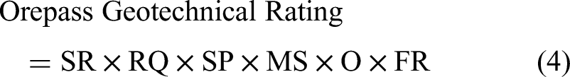
The OGRE categories are described in detail in the following sections, along with corresponding tables of how the modifying reduction factor (MRF) is calculated. The OGRE is presented in an effort to assist geotechnical or mine planning engineers in understanding the geotechnical risk for each potential orepass location. The overall rating of an orepass is calculated by multiplying the MRF of each of the six categories together, as shown in equation (4), where SR is the MRF for stress regime, RQ is the MRF for rock quality, SP is the MRF for sulfide potential, MS is the MRF for major structure, O is the MRF for orientation, and FR is the MRF for finger raise or knuckle use. The lower bound of MRF values ranges from 0.05 to 0.7. If the lowest MRF value is applied for every category, the resulting value would be approximately 0. This calculation is adapted from Hadjigeorgiou and Mercier-Langevin (2008) and Sredniawa et al. (2022):
Stress regime
The MRF for the orepass stress regime is kept the same as in the Sredniawa et al. (2022) system, as shown in Table 1. The range of the MRF is from 0.5 to 1.0. While the stress regime can change with orepass cross-sectional dimensions and shape, that is not considered in this geotechnical evaluator. That is because it is assumed that the orepass excavation method, which most commonly dictates the orepass shape and dimensions, should remain consistent regardless of which orepass in a given area is chosen to construct. It is important to note, however, that the stress regime may impact what excavation method is to be used to ensure long-term stability. Rock stresses may also impact the generation of new fractures and thus decrease overall orepass stability (Salmi et al., 2025). Additionally, the stress profile may change with mining activity, so it is important to place orepasses outside of the effected stress envelopes or incorporate this into potential location decisions (Salmi et al., 2024b).
Stress regime calculator table.
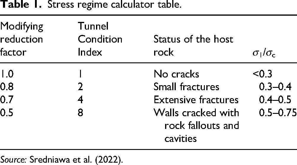
Source: Sredniawa et al. (2022).
Rock quality
The MRF related to the rock quality category, that is, the RMR (Bieniawski, 1989), is kept the same as in the Sredniawa et al. (2022) system, as shown in Table 2. The range of the MRF is from 0.05 to 1.0 for rock quality, which also has the most significant impact on the geotechnical rating. However, if an orepass is placed in an area where it travels through multiple RMR zones, we recommend a more conservative approach for the engineer to decide if the lowest RMR value or a weighted average should be used.
Rock quality calculator table.
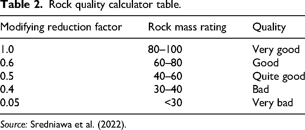
Source: Sredniawa et al. (2022).
An analysis of common orepass issues and accidents by Stacey and Erasmus (2005) in South African mines led to the conclusion that “…locations of passes should be chosen to avoid poor rock if possible…”. Additionally, the U.S. Mine Safety and Health Administration recognizes the correlation between injuries from roof falls in underground mines and extremely difficult ground conditions associated with mining in a weak rock mass (Pakalnis et al., 2007). This relationship highlights the importance of understanding the rock mass at an operation, especially when structures travel through multiple RMR zones, and of understanding the potential consequences of having infrastructure in areas with poor or very poor RMR ratings. In terms of risk, an orepass that has a bulge can cause more hang-ups or even a wedge failure of the orepass walls. Additionally, the cost for constructing an orepass could be elevated as orepass support will likely be needed. These concerns were further highlighted in an interview with a Canadian Senior Ground Control Engineer (Canadian Senior Ground Control Engineer, 2024).
Sulfide-generating potential
The addition of the MRF for the sulfide-generating potential of the orepass host rock was added based on the survey results and interviews conducted on orepass planning, design, and construction in Canada and the United States (Guerin-Davey and Brickey, 2025).
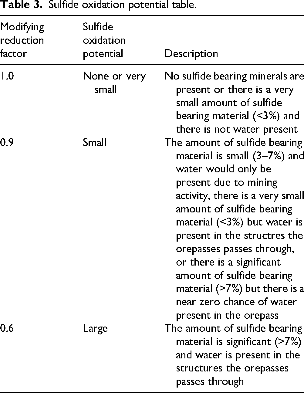
The proposed MRF for an orepass based on the sulfide-generating potential is listed in Table 3. The range of the MRF is from 0.6 to 1.0. There is a significant change in the MRF between the small and large sulfide oxidation potential categories, as there is a significant amount of damage to an orepass that can result from sulfide oxidation. If there are no sulfides present, then there is no risk. If there is a small amount of sulfides, and/or there is no water present, then it is a low sulfide oxidation potential. If there is a large amount of sulfides present, and there is also water, then it is a high sulfide oxidation potential. Previous research (Woo et al., 2013) suggests that at 3.3 wt% pyrite, there is not a strong influence on the weathering rate, but at 5.5 wt% pyrite, there is a strong influence on the weathering rate of the rock. It is up to each operation to determine their sulfide oxidation and water infiltration potential, though common sulfide minerals (Perkins, 2022) include:
Pyrite ( Chalcopyrite ( Molybdenite ( Sphalerite ( Galena ( Cinnabar (
Sulfide oxidation potential table.
Major structure
The MRF for the orepass major structure is kept the same as in the Hadjigeorgiou and Mercier-Langevin (2008) system, as shown in Table 4. The range of the MRF is from 0.5 to 1.0. Potential interaction between orepasses and major geological structures has a high potential for adverse effects on the orepass. If the orepass does intersect a major geological feature, such as a major fault, it is more likely to cause orepass instability, large structural failure, wall degradation, or even collapse (Stacey and Erasmus, 2005; Salmi et al., 2025). There is also a higher probability that water will flow into the pass if it intersects a major geological feature, due to increased rockmass permeability (Salmi et al., 2025).
Major structure calculator table.
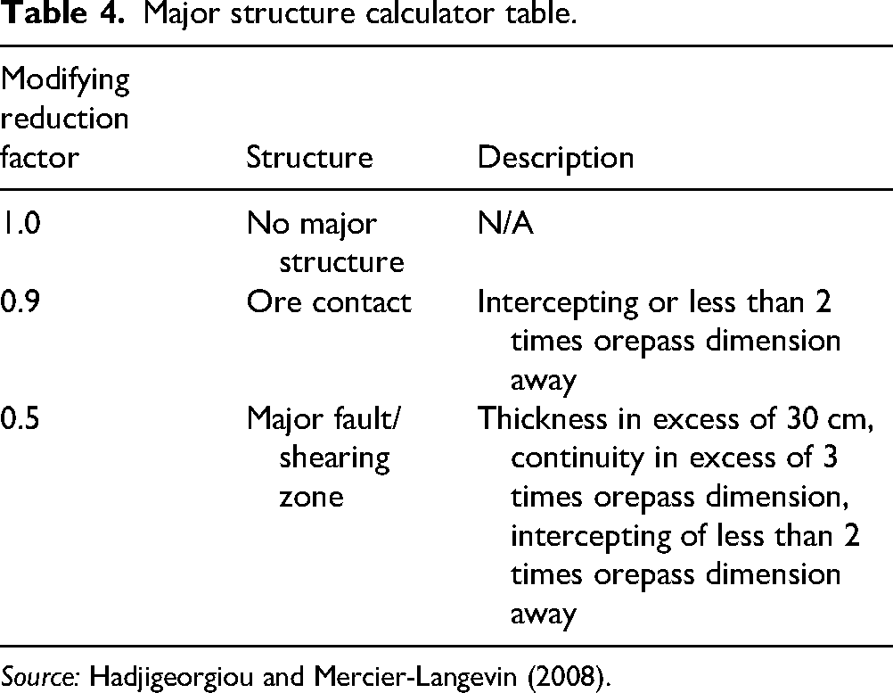
Source: Hadjigeorgiou and Mercier-Langevin (2008).
Orientation
The MRF based upon orepass orientation relative to the bedding plane or joint set (x) was modified from the Hadjigeorgiou and Mercier-Langevin (2008) version to address specific concerns around wedge failure. The range of the MRF is from 0.3 to 1.0. Additional aspects in the OGRE included are the tipping point alignment with the orepass and the angle at which the finger raise intersects the bedding plane (y). These angles are shown in Figure 2. It is most desirable to have the orepass or finger raise not in line (within 45°) with the bedding plane.
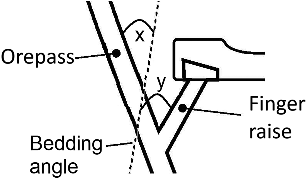
Angle measurement between the bedding plane and orepass x, and bedding plane and finger raise y.
Esmaieli and Hadjigeorgiou (2014) noted that it is common for the tipping point to be aligned such that the material hits the wall of the orepass, and that this is a major contributor to wall degradation. This article also noted that microcracks were observed where material impacted the orepass walls, even with different orepass inclinations with respect to bedding planes. These microcracks can then penetrate further into the orepass wall, interacting with the microcracks associated with the bedding plane or joint sets, and creating wedge failures (Sivakugan et al., 2013; Salmi et al., 2025). Wedge failures can potentially create large blocks of material within the orepass itself, leading to further wall degradation or even blocking of the orepass. The chance of wedge failure is also increased with the presence of water (Salmi et al., 2025).
It is also important to consider the angle between any finger raises, if used, and the bedding plane. The same interception angles are considered for the finger raise interception angle, y, as for the overall orepass interception angle, x, in the OGRE. The impact damage done to the orepass walls from the discharge point of finger raises is considered in the Finger Raise or Knuckle Use subsection. The MRF based upon orepass orientation is presented in Table 5.
Orepass orientation calculator table.
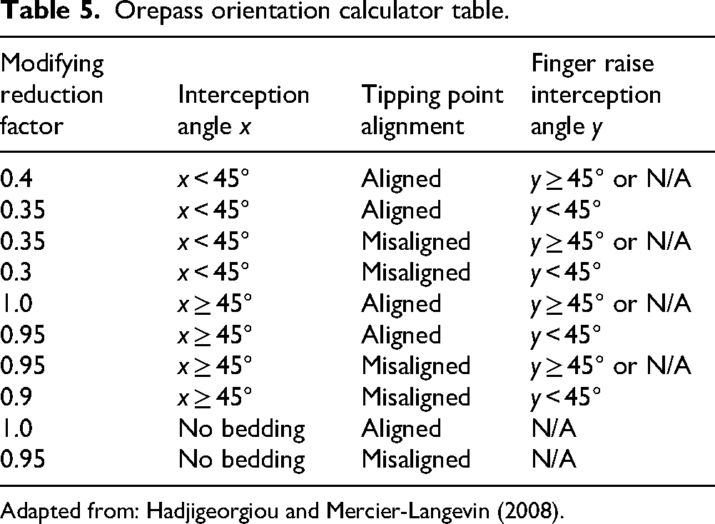
Adapted from: Hadjigeorgiou and Mercier-Langevin (2008).
Finger raise or knuckle use
The MRF for finger raises or knuckles used for this OGRE is slightly modified from the Hadjigeorgiou and Mercier-Langevin (2008) version. The range of the MRF is from 0.7 to 1.0. The MRF was modified to include the effect of the angle between the finger raise and orepass, as shown in Table 6.
Finger raise or knuckle calculator table.
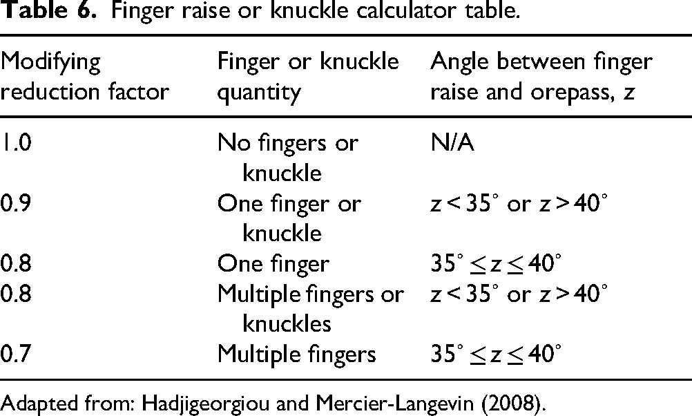
Adapted from: Hadjigeorgiou and Mercier-Langevin (2008).
The use of finger raises in an orepass will often result in damage at the intersection of the finger raise and the orepass (Salmi et al., 2024b; Salmi et al., 2025). The angle of intersection, as shown in Figure 3, influences the extent of potential wall damage. A study on finger raise and orepass configurations was conducted by Esmaieli and Hadjigeorgiou (2011). Their article demonstrated that the most damage occurs when the intersection angle of the finger raise and orepass is between 35° and 40°. Additionally, if finger raises are long and/or steep, the material velocity can increase, and when it impacts the orepass wall opposite the discharge point, it can create extensive damage. It is important to note that material within an orepass must be kept below the lowest operational finger raise, which means that material within the pass cannot be used to absorb the kinetic energy from the material and reduce degradation to the orepass walls. Multiple finger raises can cause multiple areas of localized damage at intersection areas, creating turbulence in the flow of material through the pass and exacerbating damage (Salmi et al., 2025).
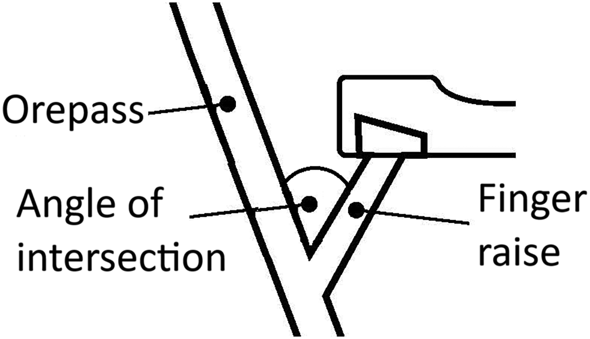
Angle measurement between orepass and finger raise. Source. (Guerin-Davey and Brickey, 2025).
This information was incorporated into the geotechnical rating system in order to make planning engineers aware of the potential effects of configuration angles and to encourage the use of angles that result in less damage.
Potential mitigation strategies
If the OGRE shows that no orepass options have an acceptable level of risk, an operation can employ mitigation strategies. Altering planned operational parameters, such as changing cushion guidelines from running empty to running full if there is not a risk of water, could provide more orepass stability (Skawina et al., 2022).
Another method to decrease the geotechnical risk of an orepass is to provide support to the orepass. Support systems could include rock bolting from within the pass or outside the pass, shotcrete, installing liners, or a combination of these methods (Salmi et al., 2024a). Liners may also reduce impact damage to the rock mass from material moving through the pass (Salmi et al., 2025). An important aspect to consider when adding a support method is the maintenance of the system. If the support system cannot be easily maintained, it is likely to increase the chance of orepass issues, such as hang-ups, as it wears and falls into the orepass itself (Salmi et al., 2024b).
Construction methods, such as the use of a raisebore or conventional drill and blast drop raise, can also impact the overall stability of an orepass. The use of drill and blast can reduce the stability of the orepass walls (Stacey and Swart, 1997), and operations should consider changing the construction method to raisbore or Alimak development (potentially by hiring a contractor) if rock quality is an issue.
Case study
The data for this analysis are from a large underground gold mine in the western USA. As exploration drilling continues at the operation, new stoping districts are being discovered and incorporated into the operation. This project looks at a specific stoping district within the overall underground operation with the objective of placing two orepasses to serve the area. There are three levels, each with stopes, which will be connected from the orepass, as shown in Figures 4 and 5.
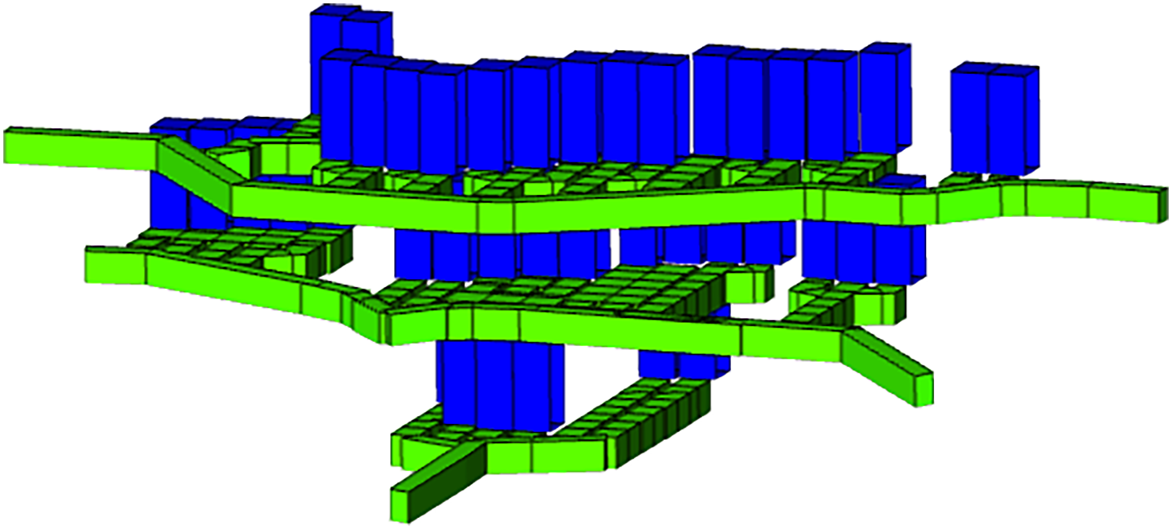
Left stope layout.
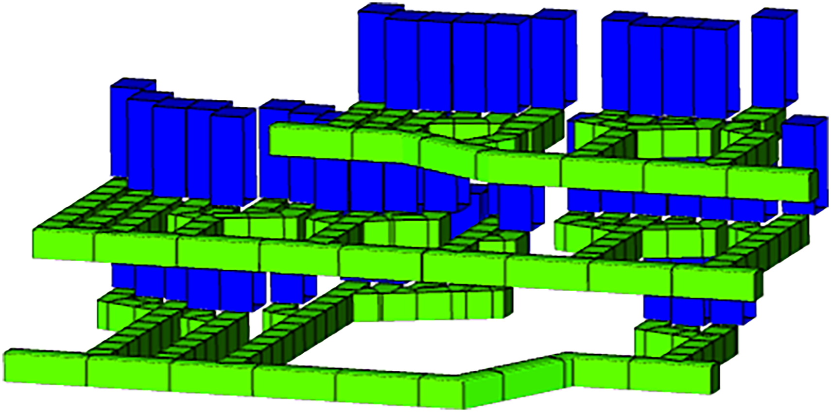
Right stope layout.
There are multiple company standard rules for orepass placement. Orepasses are inclined at 80° from horizontal. The required offset from the top and middle drifts was 15 m (50 ft), though it can be up to 30.5 m (100 ft) if necessary to avoid interaction with other infrastructure. On the bottom level, the orepass should be within 30.5 m (100 ft) of the drift. Additionally, orepasses need to be at least 18 m (60 ft) from existing or planned infrastructure and will be constructed with a raiseborer.
Mine planning is carried out using the Deswik software package. Currently, orepass placement is not part of the life-of-mine planning process. Instead, particular areas that will require an orepass are noted, but no orepass location is specified. The operations department will communicate with the engineering department when they feel it is time for a new orepass, usually because they feel the cycle time of the LHD from the stope to the current orepass is too long. At this point, the engineering department will work within the current short-term plan and other planned infrastructure and development to place an orepass. This can lead to orepasses being placed in less than desirable geotechnical locations, and the potential for better orepass placement if orepasses were planned at a higher level than the immediate future.
To test the geotechnical rating system, orepass options were created within the given stoping district. The stoping district was split into two areas, the left and the right. Following the aforementioned design rules, a total of 67 orepasses were placed in the left district and 51 in the right district for a total of 118 options. This is shown in Figures 6 and 7. Orepass options were placed parallel to the main drifts at a 3 m interval (10 ft) and modified if necessary to meet the required 19 m (60 feet) offset from existing or planned infrastructure.
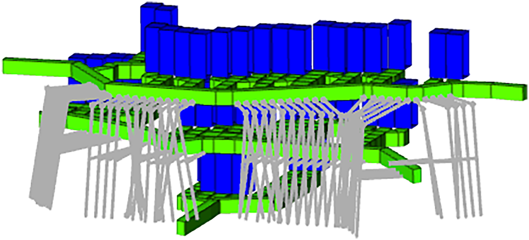
Left stope layout with 67 orepass options.
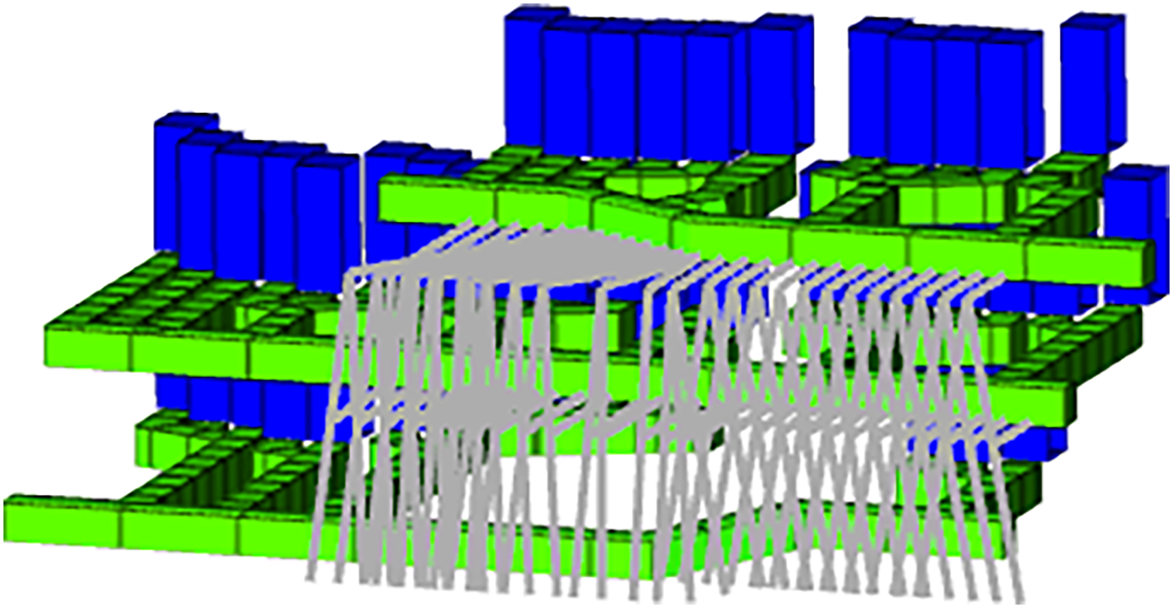
Right stope layout with 51 orepass options.
Case study results
The proposed OGRE was applied to the 118 orepass location options (67 in the left stoping district and 51 in the right stoping district) from the case study operation. This allowed all orepass options to be compared to assist the operation in determining which orepass in each stoping district should be constructed. During this analysis, it was noted that three of the six categories had the same value across all 118 orepasses. In this case, the value for these three categories was set to 1.0 as the value was consistent, and it no longer usefully impacted the orepass ratings. The three categories that were constant for all considered orepasses were: (i) stress regime, (ii) major structure, and (iii) finger or knuckle use. Once these categories were set to the nominal value of 1.0, the 118 orepasses were evaluated based on the remaining categories: (i) rock quality, (ii) sulfide-generating potential, and (iii) orientation.
Left-stoping district results
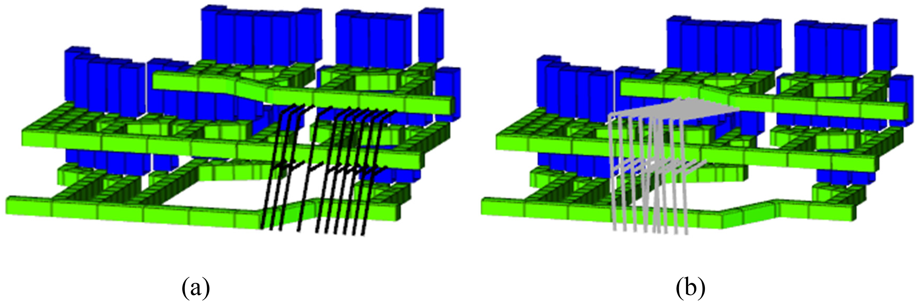
The 67 orepass location options in the left stope layout returned values ranging from 0.48 to 0.02. The 10 highest OGRE scores, shown in Figure 8(a), had values from 0.38 to 0.48. The 10 lowest OGRE scores, shown in Figure 8(b), had returning values from 0.02 to 0.11.
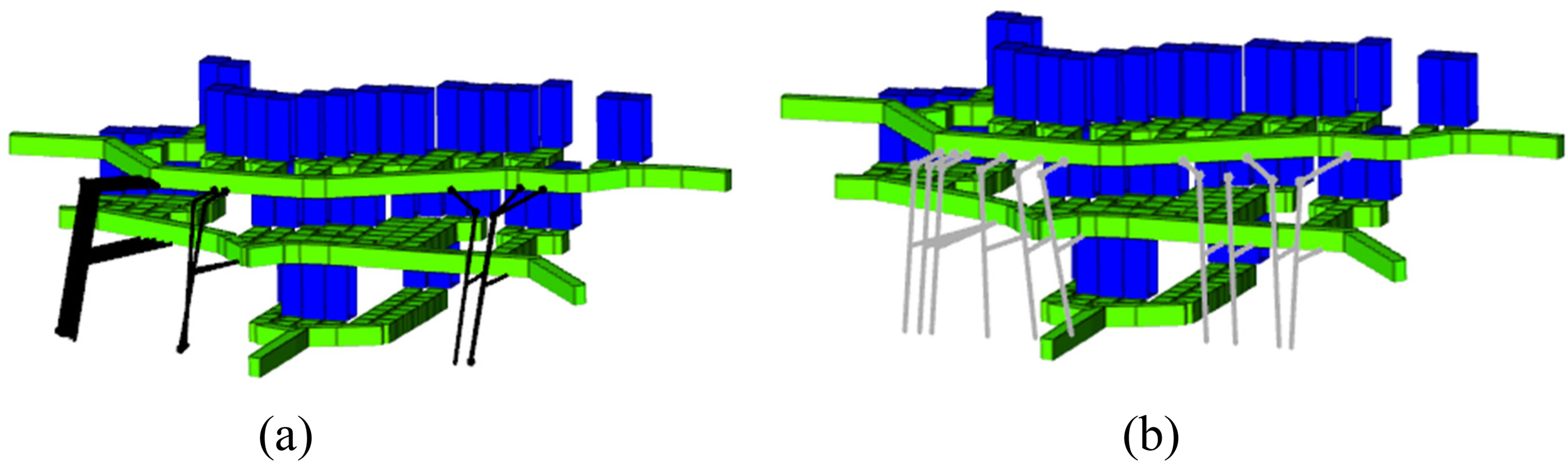
Left stope district showing (a) 10 highest OGRE scores; (b) 10 lowest OGRE scores.
To fully understand the impact of the rock quality, sulfide-generating potential, and orientation categories, it is useful to look at two orepasses that returned different values but are spatially very close together. Two case studies of this in the left stoping district are shown in Figures 9 and 10.
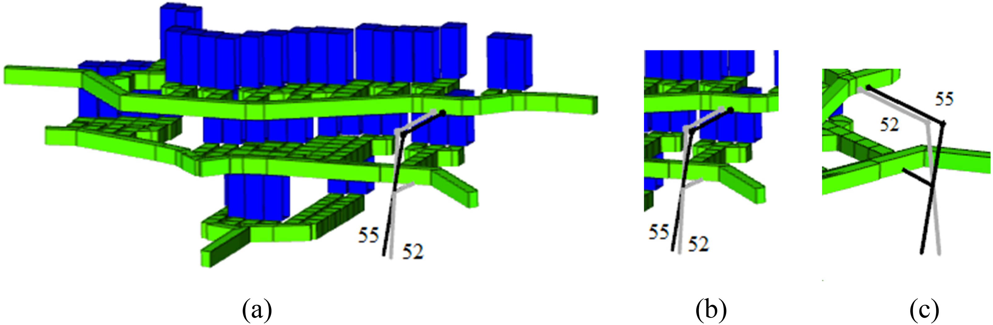
Comparison of Orepass 52 and 55 in the left stoping district. Orepass 52, starting on the left, has a value of 0.11, where Orepass 55, shown starting on the right, has a value of 0.43.
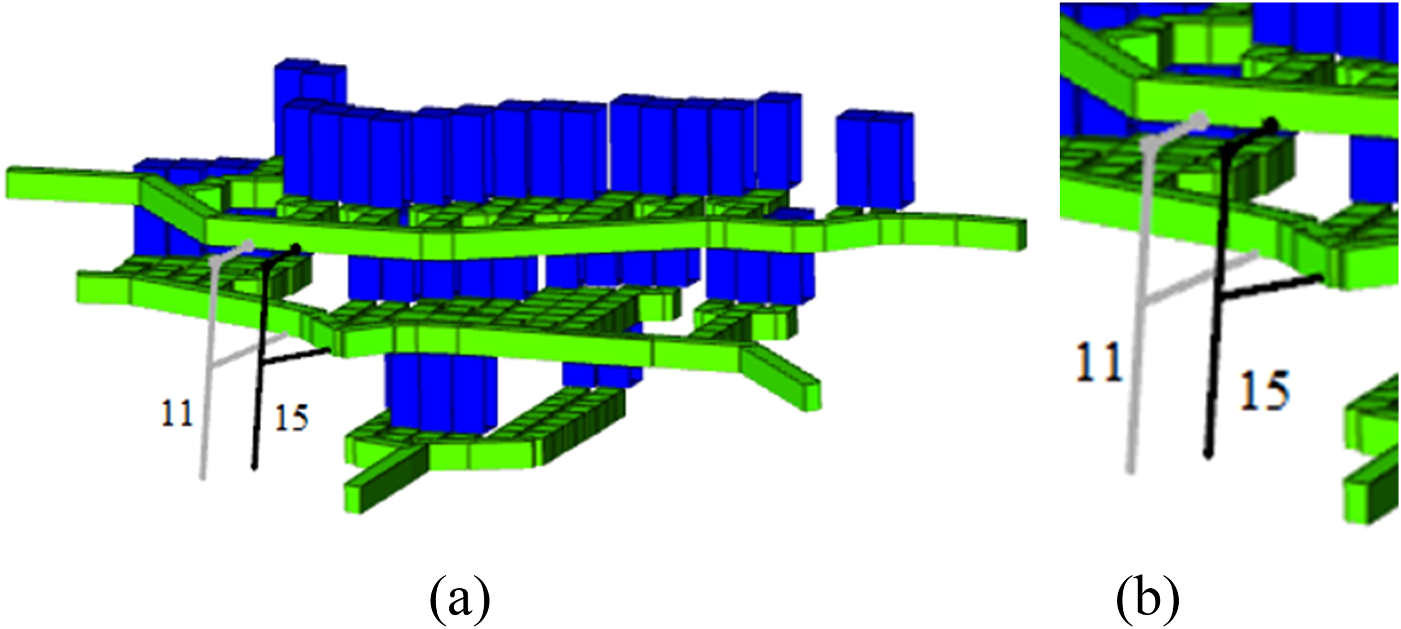
Comparison of Orepass 11 and 15 in the left stoping district. Orepass 11, seen on the left, has a value of 0.02, where Orepass 15, seen on the right, has a value of 0.45.
The RMR of Orepass 55, shown starting on the right in Figure 9, is between 40 and 60, and the orientation of both the orepass and finger raise is not in line with the bedding plane, even though the tipping point is misaligned with the pass, causing it to have a higher overall value of 0.43, as shown in Table 7. Orepass 52, shown starting on the left in Figure 9, has an RMR value between 30 and 40, and both the orepass and finger raise are aligned with the bedding plane, plus the tipping point is misaligned with the pass, causing a very low overall value of 0.11, as shown in Table 7. Both orepasses have a small sulfide-generating potential, as they contain 3–7% sulfide material, but do not intersect faults known to carry water. This comparison highlights the impact of orientation with respect to the bedding plane, as both orepasses have the same sulfide-generating potential, misaligned tipping points, and are spatially very close to each other. In this case, the impact of the rock quality category differences is outweighed by the impact of the orepass orientation category.
Left stoping district, Orepass numbers 52 and 55.
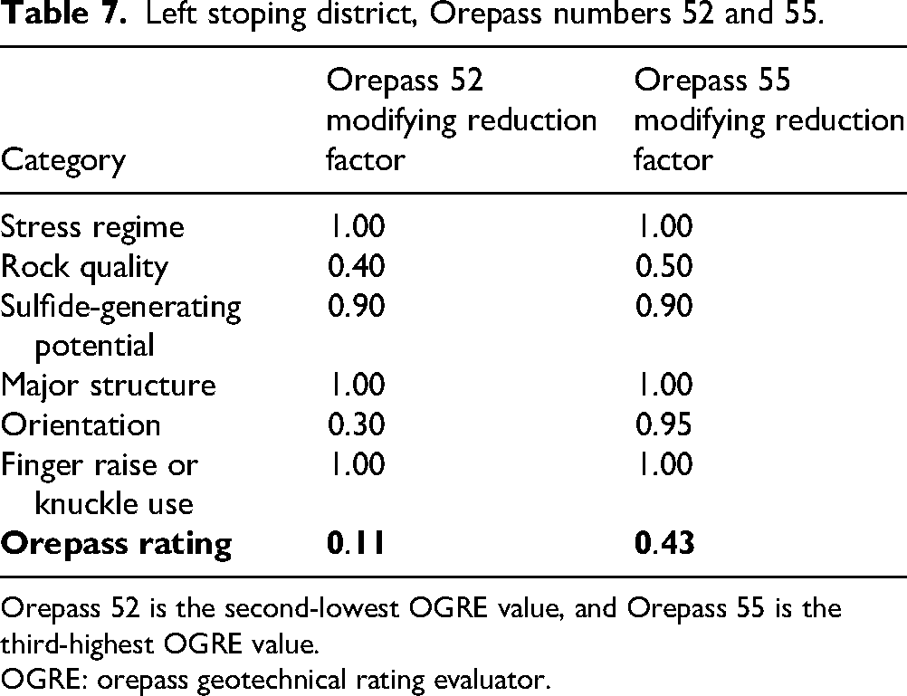
Orepass 52 is the second-lowest OGRE value, and Orepass 55 is the third-highest OGRE value.
OGRE: orepass geotechnical rating evaluator.
Another comparison of two orepasses that are relatively close together (around 9.1 m or 30 ft) but have significantly different geotechnical ratings is shown in Figure 10.
The RMR of the right orepass (Orepass 15) in Figure 10 is between 40 and 60. The orientation of the orepass returns a reasonable value, even though the tipping point is misaligned with the pass and the finger raise is in line with the bedding plane; the main orepass is not in line with the bedding plane. There are also less than 3% sulfides present in the host rock, and no water present, causing this orepass to have a higher overall value of 0.45, as shown in Table 8. The right orepass (Orepass 11) in Figure 10 has a “very poor” RMR value of less than 30, and both the orepass and finger raise are aligned with the bedding plane, though the tipping point is aligned with the pass. Additionally, there are 3–7% sulfide materials, but little chance of water as the orepass does not intersect a fault known to carry water, causing a very low overall value of 0.02, as shown in Table 8. This comparison shows the drastic effect that the rock quality category can have on the geotechnical rating of an orepass, even though there is also a significant impact from orepass orientation category and a slight impact from sulfide-generating potential category.
Left stoping district, Orepass numbers 11 and 15.
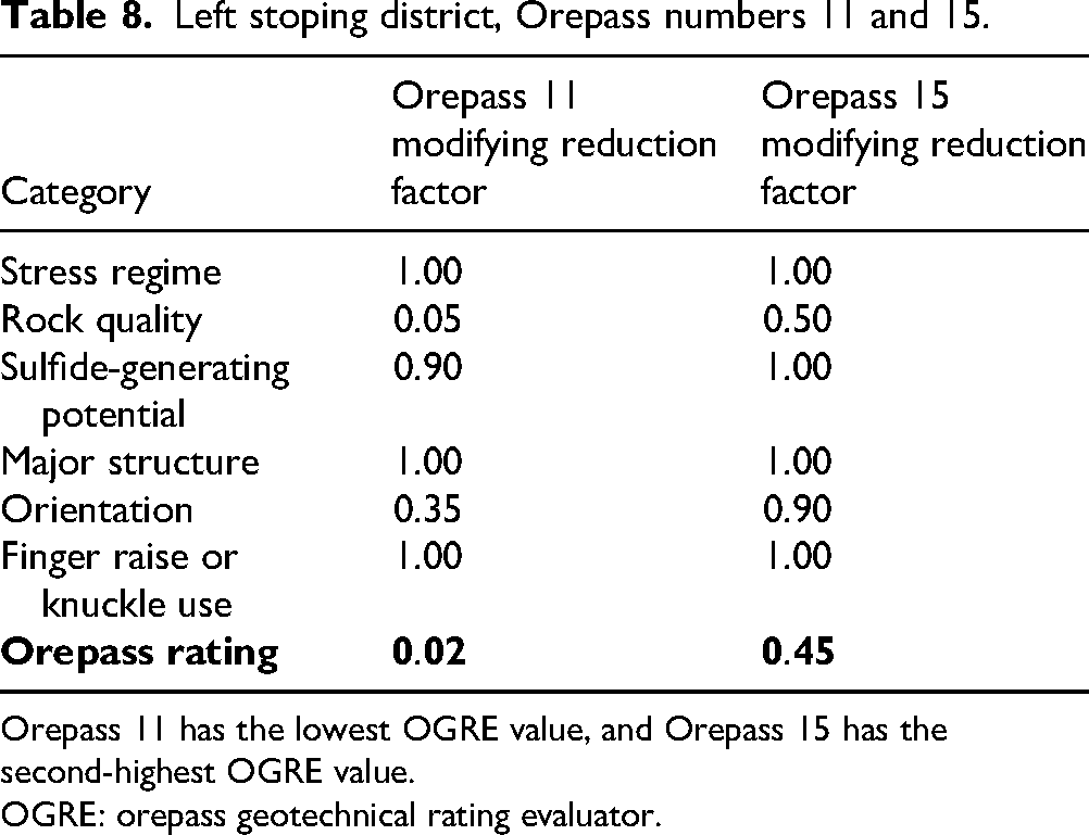
Orepass 11 has the lowest OGRE value, and Orepass 15 has the second-highest OGRE value.
OGRE: orepass geotechnical rating evaluator.
Right-stoping district results
The 51 orepass location options in the right stope layout returned values between 0.54 and 0.11. The 10 highest OGRE scores, shown in Figure 11(a), had returning values between 0.45 and 0.54. The 10 lowest OGRE scores, shown in Figure 11(b), had returning values ranging from 0.11 to 0.14.
Right stope district showing (a) 10 highest orepass geotechnical rating evaluator (OGRE) scores; (b) 10 lowest OGRE scores.
The overall RMR values of the right stoping district are generally of higher quality than in the left stoping district, causing the geotechnical ratings to be more impacted by the orepass orientation or sulfide-generating potential categories. The following case in the right stoping district, shown in Figure 12, highlights the impact of the orientation of the orepass and finger raise with respect to the bedding plane.
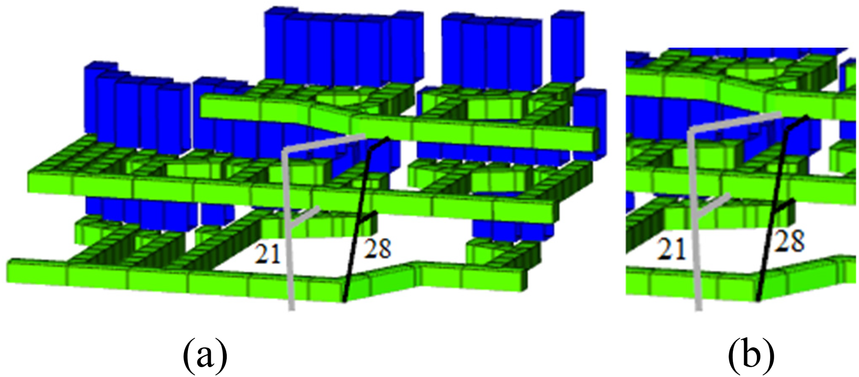
Comparison of Orepass 21 and 28 in the right stoping district. Orepass 21, seen on the left, has a value of 0.14 where Orepass 28, seen on the right, has a value of 0.54.
The RMR of the right orepass (Orepass 28) is “good,” at 60–80, and the orientation of the orepass is not in line with the bedding plane, though the finger raise is in line with the bedding plane, and the tipping point is misaligned with the orepass. Additionally, there are less than 3% sulfides present in the host rock, and no water present, causing this pass to have a higher overall value of 0.54, as shown in Table 9. Interestingly, the left orepass (Orepass 21) has a “quite good” RMR value of 40–60; however, both the orepass and finger raise are in line with the bedding plane, and the tipping point is misaligned. Additionally, there are 3–7% sulfide materials, though little chance of water, as the orepass does not intersect a fault known to carry water, causing a very low overall value of 0.14, as shown in Table 9. This comparison clearly shows the impact of improperly aligned orepasses in respect to the bedding plane on the overall geotechnical rating, even if the RMR value is “quite good.”
Right stoping district, Orepass numbers 21 and 28.
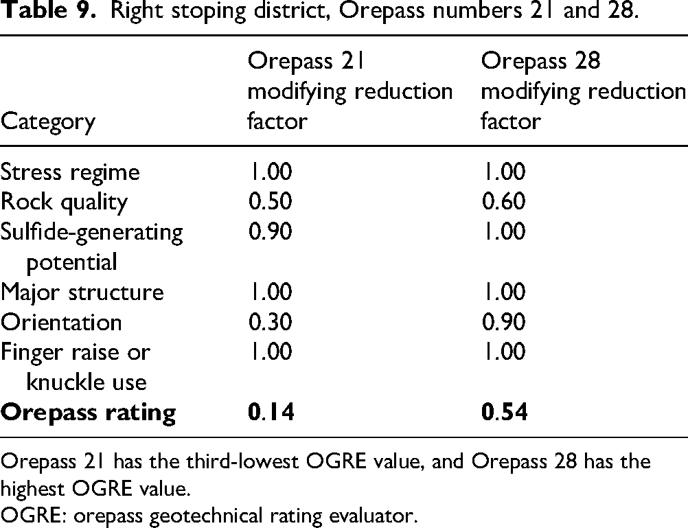
Orepass 21 has the third-lowest OGRE value, and Orepass 28 has the highest OGRE value.
OGRE: orepass geotechnical rating evaluator.
Validation
Upon completion of the analysis using the OGRE, the evaluator tool and results were presented to engineers and management at the case study operation. It was emphasized that this tool is a preliminary risk evaluator, but it does show drastic impacts of different RMR regions and orepass orientation. Great interest was shown in the evaluator tool, which can be simply rebuilt using the information in the Appendix (Table A1: OGRE system), or a template is available if you contact the corresponding author.
The OGRE tool and results assisted the operation in understanding the geotechnical risk of placing orepasses in different locations and evaluating this risk objectively and systematically. Additionally, understanding the impacts to the OGRE score from misalignment of the tipping point to the orepass and overall alignment with respect to the bedding plane helped the operation determine the ideal orientation range in this mine region.
The use of the OGRE tool allows mine engineers to not only consider distance from stopes to an orepass but also the stability (and thus longevity) of the orepass itself. As studied by Skawina et al. (2016), when an orepass becomes inoperable, either temporarily by a hang-up or longer term due to instability by massive cross-sectional expansion, it negatively impacts production. Even if multiple LHDs or trucks are used to move material from the stope, it is unlikely that the same level of production can be achieved. This becomes even more essential if the operation does not mine in multiple areas and cannot compensate for a district's lack of production by increasing production elsewhere.
The ability to evaluate orepass options on both distance from stopes and geotechnical stability provides mine engineers the opportunity to move orepass planning into the medium- or long-term planning strategy to ensure orepasses are placed in more opportune locations. This decision can be justified by the above case study as even orepasses spatially close together can have drastically different OGRE values, which translates to an increased chance of premature orepass failure and a negative impact on production. Though other infrastructure, such as shafts or declines, may require placement in the most geotechnically stable areas, evaluating different orepass location options, even within a spatially limited area, with the OGRE tool can provide insight into where the best available location is.
Conclusion
The conversion of the OLC to an OGRE provides a tool for geotechnical and mining engineers to understand the geotechnical risk of orepass placement within their operations. By evaluating possible orepass locations within a given area based upon (i) stress regime, (ii) rock quality, (iii) sulfide-generating potential, (iv) major structures, (v) orientation, and (vi) finger raise or knuckle use, the impact of location and design on the stability of an orepass can be determined. Each category's modifying reduction value is multiplied together to provide a total value between approximately 0 and 1.00. It is up to each operation to determine what the acceptable level of geotechnical risk is, but using this tool can help operations understand the risk to safety and production for orepasses in given locations before they decide.
The stress regime category considers the extent of fractures within the host rock, while the rock quality category is based on the RMR. By understanding the stability of the host rock, the stability of the orepass walls can be incorporated into the equation. The sulfide-generating potential category assists in quantifying the risk of oxidation within the orepass walls, while the major structure category quantifies the wall stability effect that intersecting a fault has. The OGRE builds upon previous OLCs to produce a system capable of quantifying the geotechnical risk of certain orepass locations.
The two categories that operations have the most control over with respect to orepass placement in the geotechnical evaluator are orientation and finger raise or knuckle use. If the orepass or finger raise is improperly aligned with the bedding plane, the risk of rapid cross-sectional expansion is greater. Additionally, if the tipping point is misaligned with the pass, there is the potential for material to bounce down the entirety of the pass. While finger raises might need to be included to service multiple levels, ensuring that the angle between the finger raise and orepass is outside of the 35°–40° window (shown to cause the highest impact of material on the orepass walls at the discharge point) will not reduce the rating as much.
The case study mine and data presented show the functionality of the OGRE. The impacts of different categories are shown through orepasses relatively close together but with vastly different ratings. If there are known areas of low RMR, placing an orepass outside of this window can improve the stability of the pass, or simply changing the alignment so it is not within 45° of the bedding plane will also drastically improve the geotechnical rating. If the calculated geotechnical ratings are not acceptable to the operation, there are potential mitigation strategies that can be employed to improve the geotechnical stability of the orepass.
Future research could include incorporating this geotechnical rating system of orepass options into schedule optimization, or even just long-term mine planning. Research has shown that concurrent optimization, as opposed to sequential optimization, achieves a better objective function value, usually an operation's Net Present Value. The benefit of this research is two-fold: orepass planning could be easily incorporated into the strategic (long term) mine plan, and the risk of orepass failure would be reduced due to optimized orepass placement.
Footnotes
Acknowledgements
The authors would like to thank the National Institute for Occupational Safety and Health (NIOSH) for partially funding this research under contract 75D30119C06090 and contract 75D30124C20308. The authors would also like to thank our industry partner and company contact for providing data and feedback for this project.
Funding
The authors disclosed receipt of the following financial support for the research, authorship, and/or publication of this article: This work was supported by the National Institute for Occupational Safety and Health (NIOSH), (grant number 75D30119C06090, 75D30124C20308).
Declaration of conflicting interests
The authors declared no potential conflicts of interest with respect to the research, authorship, and/or publication of this article.
Appendix A: Orepass Geotechnical Rating Evaluator
Orepass geotechnical rating evaluator (OGRE) system.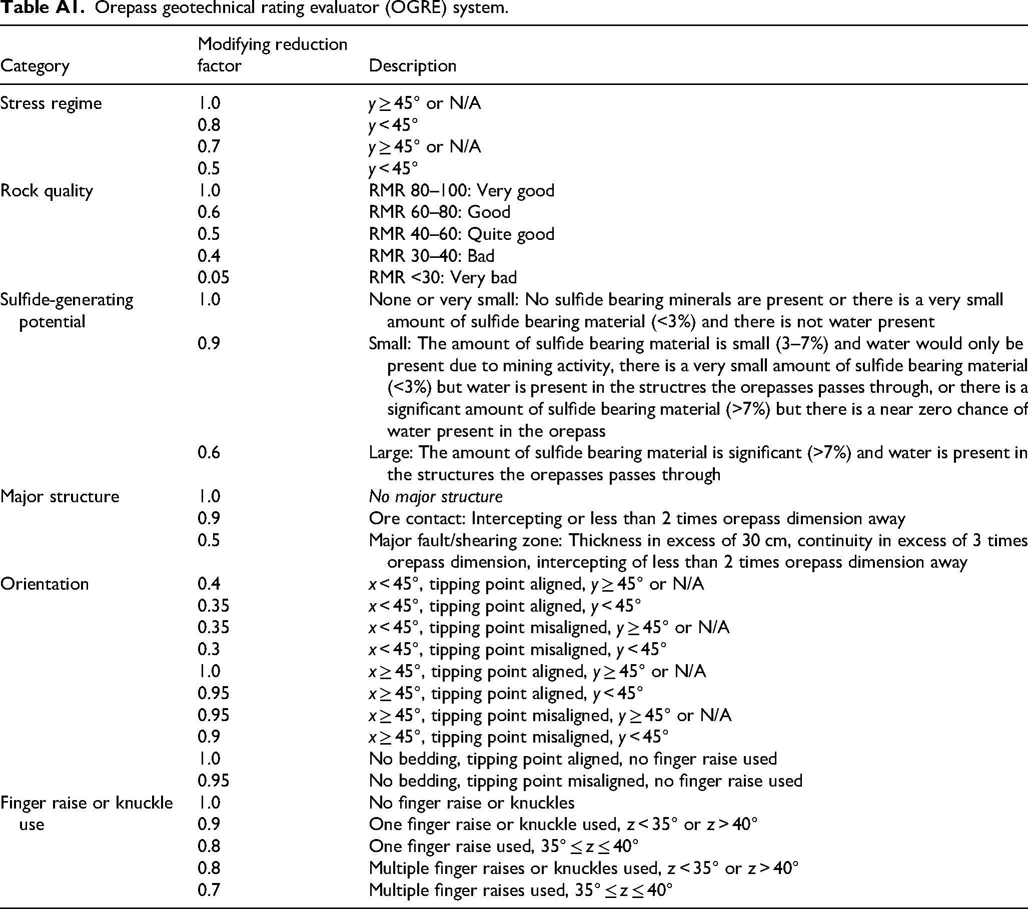
Category
Modifying reduction factor
Description
Stress regime
1.0
y ≥ 45° or N/A
0.8
y < 45°
0.7
y ≥ 45° or N/A
0.5
y < 45°
Rock quality
1.0
RMR 80–100: Very good
0.6
RMR 60–80: Good
0.5
RMR 40–60: Quite good
0.4
RMR 30–40: Bad
0.05
RMR <30: Very bad
Sulfide-generating potential
1.0
None or very small: No sulfide bearing minerals are present or there is a very small amount of sulfide bearing material (<3%) and there is not water present
0.9
Small: The amount of sulfide bearing material is small (3–7%) and water would only be present due to mining activity, there is a very small amount of sulfide bearing material (<3%) but water is present in the structres the orepasses passes through, or there is a significant amount of sulfide bearing material (>7%) but there is a near zero chance of water present in the orepass
0.6
Large: The amount of sulfide bearing material is significant (>7%) and water is present in the structures the orepasses passes through
Major structure
1.0
No major structure
0.9
Ore contact: Intercepting or less than 2 times orepass dimension away
0.5
Major fault/shearing zone: Thickness in excess of 30 cm, continuity in excess of 3 times orepass dimension, intercepting of less than 2 times orepass dimension away
Orientation
0.4
x < 45°, tipping point aligned, y ≥ 45° or N/A
0.35
x < 45°, tipping point aligned, y < 45°
0.35
x < 45°, tipping point misaligned, y ≥ 45° or N/A
0.3
x < 45°, tipping point misaligned, y < 45°
1.0
x ≥ 45°, tipping point aligned, y ≥ 45° or N/A
0.95
x ≥ 45°, tipping point aligned, y < 45°
0.95
x ≥ 45°, tipping point misaligned, y ≥ 45° or N/A
0.9
x ≥ 45°, tipping point misaligned, y < 45°
1.0
No bedding, tipping point aligned, no finger raise used
0.95
No bedding, tipping point misaligned, no finger raise used
Finger raise or knuckle use
1.0
No finger raise or knuckles
0.9
One finger raise or knuckle used, z < 35° or z > 40°
0.8
One finger raise used, 35° ≤ z ≤ 40°
0.8
Multiple finger raises or knuckles used, z < 35° or z > 40°
0.7
Multiple finger raises used, 35° ≤ z ≤ 40°