






Abstract
Cell stimulation with electric fields (EFs) can be used for a variety of purposes. Among the different types of EFs, pulsed EFs (PEFs) have been extensively employed to induce cell membrane electropermeabilization. This approach can be used as a vectorization method to introduce inside cells compounds whose dimensions may range from the size of an ion to the size of a large nucleic acid. Thus, there is a wide scope of applications for electropermeabilization. For example, the use of PEFs of microseconds duration (µsPEFs) has been shown to be a convenient tool to modulate calcium (Ca2+) oscillations in mesenchymal stem cells (MSCs) by generating a limited and controlled electropermeabilization to external Ca2+ ions. These data highlight the interest in developing methodologies suitable for long-term electric stimulations. We describe here a device that allows the delivery of µsPEFs to attached cells, in a classical Petri dish, in a long-term manner, while ensuring the maintenance of sterility. This device is simple, easy to elaborate at a low cost, and it allows to perform multiple experiments in parallel, as well as microscopy recordings during (and/or after) the delivery of µsPEFs to cells, a very convenient approach to directly assess the effects of the electrical stimulations. The conception of the system prevents medium leaks by capillarity, which allows avoiding losses of the medium and its potential contamination. We also analyzed the geometry of the electrodes and demonstrated the superiority of the plate electrodes compared with wires when the most homogeneous field distribution on the cell layer is sought. The choice of the material constituting the electrodes, in terms of cost and limited electrochemical reactions, is also discussed. The interest of this cost-effective device is documented with an example dealing with the control of Ca2+ cytosolic oscillations in MSCs.
Keywords
Introduction
The investigations about the effects of electric fields (EFs) on living cells have a long history. Bioelectricity arises from a differential accumulation of electrical charges inside and outside the cell, the homeostasis being maintained by the passive flux of ions across the cell membrane or their active movement through ion channels, among other processes. This differential accumulation of electrical charges inside and outside the cell generates what is called the transmembrane potential difference ΔTMP (or transmembrane voltage, TMV). 1 It is possible to manipulate this ΔTMP/TMV using various forms of electrical stimulation. Nowadays, different types of EFs, whose properties greatly differ, can be used according to the desired application, in line with the evolution of electrical engineering over the last few decades. Dating back to 1780, Luigi Galvani’s work on frog muscle contraction, which he called “animal electricity,” was subsequently described by Alessandro Volta as direct current (DC) electricity arising from the different metals used to stimulate the frog leg. 2 This eventually inspired Volta to create the Voltaic pile, the first device able to produce steady electric current. 2 Since then, the application of DC fields has been used to perform cell electrotaxis, 3 to promote axon guidance, 4 to influence cell proliferation or differentiation,5,6 or even to modulate neuronal excitability. 7
Although the effects of electrical discharges have fascinated mankind from antiquity, with the use of the Torpedo fish for pain relief in headaches or gout crises, for instance,8,9 the controlled application of pulsed EFs (PEFs), with defined discharges of capacitors, is a more recent development. The development of the first device specifically designed for this purpose dates back to 1961 with the work of Heinz Doevenspeck. 10 It was later discovered that such pulses could permeabilize the cell membrane, and the phenomenon was named electroporation. 11 Electroporation, also termed electropermeabilization (although both terminologies do not exactly refer to the same phenomenon), can not only serve various purposes, such as the vectorization of small and large molecules (from the size of an ion to the size of large DNA molecules) inside the cells,12–14 but also the release of cellular components.15,16 Electroporation can as well be used to perform cell fusion 17 or to induce cell death. 18 Moreover, PEFs can also be used to induce action potentials in excitable cells.19,20
In another respect, mesenchymal stem cells (MSCs), which have been receiving increasing interest over the last few decades in the context of regenerative therapies, 21 are known to display spontaneous Ca2+ oscillations. 22 It has been shown that PEFs of microseconds duration (µsPEFs) can be used to generate a limited and controlled electropermeabilization to external Ca2+ ions, constituting a flexible tool to manipulate Ca2+ oscillations in MSCs.12,23 The outcome of the stimulation can be modulated by varying the amplitude of the EF applied. With monopolar PEFs of 100 µs duration, the application of one pulse at low field amplitude (150–250 V/cm) adds one Ca2+ oscillation similar to the natural ones. On the other hand, the application of one pulse at a higher field amplitude (450–900 V/cm) results in the induction of one Ca2+ oscillation of higher amplitude as compared with the natural ones, followed by an inhibition of the natural Ca2+ oscillations. Most interestingly, after inhibiting the natural Ca2+ oscillations in MSCs with a 100 µs pulse of high amplitude, MSCs still remain responsive to additional stimulations to induce Ca2+ oscillations. 12
The spontaneous calcium oscillations exhibited by MSCs change over the course of differentiation, 24 and it was also shown that acting on the Ca2+ oscillations using physical means can impact MSCs differentiations. 5 This highlights the interest in developing methodologies (such as electrical ones) to exert fine control on the Ca2+ oscillations in MSCs, which can imply long-term exposures to the PEFs. In this regard, sterility has to be tightly maintained while delivering the µsPEFs with the electrodes. Moreover, long-term exposures to PEFs are also associated with possible electrochemical effects at the electrodes, and this phenomenon has to be avoided as much as possible. In addition, the EF must be homogenous to ensure that all cells are exposed to the same field amplitude, required for the quality of the stimulation and the analysis of the effects related to the exposure to PEFs at well-defined and known EF parameters.
Here, we propose a device for the long-term electrical stimulation of cells in culture, addressing at a reasonable cost all the problematics mentioned above. Namely, the criteria that we set for the optimally designed and most adapted exposure device for our long-term experiments were the following:
The device should allow for the exposure of all cells to a perfectly homogeneous EF (this is a detail of utmost importance in the context of approaches such as microscopy, qPCR, or Western blot as the response of the cells analyzed must represent a response to a given EF of the ensemble of the cells seeded in the device). The electrodes should not trigger deleterious electrochemical effects. The device should allow for long-term continuous or discontinuous exposure under cell-culture conditions (in particular allowing for sterility preservation all along the manipulations). The device should allow microscopy to be performed simultaneously with EF exposure. The device should remain cost-effective to support high experimental throughput. With these criteria and aims in mind, we describe here a device prepared in simple 35 mm Petri dishes, using reusable inserts to prepare rectangular chambers in which plate electrodes can be inserted for the delivery of EFs, resulting in the homogeneous exposure of all the cells seeded in the device (as described below). Multiple investigations into the in vitro exposure of cells to electrical stimulation have already given rise to various devices that fit different experimental needs. To the best of our knowledge, devices able to ensure all our criteria were not previously described. Most devices aimed at ensuring long-term exposure to EFs in cell-culture-like conditions are not focused on exposing all cells to a perfectly homogeneous EF
25–28
nor would they allow for microscopy experiments to be conducted during exposure.
28–30
Importantly, none of the aforementioned devices, which are designed to ensure long-term low-intensity electrical stimulation, were intended for the application of middle to high field amplitude PEFs. Conversely, most devices designed for middle to high field amplitude PEF delivery only ensure short-term exposure because the applications of these PEFs, resulting in cell electroporation, tend to be transient treatments.
31,32
Materials and Methods
Cells and culture conditions
Human MSCs from adipose tissues were isolated from the surgical waste of individuals undergoing elective lipoaspiration. Samples were obtained after written informed consent from all the donors, in accordance with French and European legislations. Lipoaspirates were surgical waste and as such the French legislation (Art.L. 1245-2 du Code de la Santé Publique) establishes that the authorization from an ethics committee is not required. Every experiment was done on cells from passages 5 to 6. Cells were grown in Minimum Essential Medium Alpha Medium with GlutaMAX supplemented with 10% fetal bovine serum, 100 U/mL penicillin, and 100 mg/mL streptomycin. MSCs were cultured at 37°C in a humidified incubator with 5% CO2. Cells were passed twice a week (every passage corresponds to one doubling time of the population). To perform the electric stimulation and microscopy analysis, MSCs were seeded at a density of 5000 cells/cm2 and cultured for two days prior to the experiment.
Device construction
To expose all the cells seeded in the Petri dish to a homogenous EF, we anticipated that a simple geometry would be necessary, such as parallel electrodes, with all the cells seeded between the electrodes. Therefore, to succeed in seeding the cells in that way, it was necessary to place masks at the bottom of the 35 mm diameter Petri dishes, these masks restricting the seeding area to the simple geometry anticipated (Fig. 3). To this end, negative molds (in polylactic acid, PLA) (Supplementary Fig. S1), used to create biocompatible polydimethylsiloxane (PDMS) masks, as well as PLA holders for electrodes (Supplementary Figs. S2 and S3), were made with the 3D Printer RAISE3D N2 PLUS, running with the software IdeaMaker 4.3.1.6452. The designs were created with Autodesk Meshmixer with Inventor 2018 and can be found in the Supplementary Data (Supplementary Figs. S1, S2, and S3).
Mask fabrication
The PDMS masks fabrication was performed using the SYLGARD™ 184 Kit. Under a chemical hood, the elastomer base was homogenized with the curing agent at a 10:1 ratio. Then, the mixture was degassed under vacuum for 20 min. After degassing, for each p35 Petri dish, 4 mL of the mixture was carefully poured into the mold, that is, the negative mold placed in the Petri dish (Supplementary Fig. S1C). The polymerization proceeded at 20°C for 48 h. After demolding the PDMS mask, the traces of curing agent in the masks were eliminated by bathing the freshly polymerized masks in phosphate-buffered saline (PBS) for at least 2 h at 20°C.
Sterilization procedure of the system
Prior to their use for in vitro cell culture, the PDMS masks, PLA printed electrode guide sets, and titanium electrodes were sterilized by a chemical method, for example, in an ethanol/sterile deionized water (70/30) bath for 5 min under a laminar flow hood (note that all instruments used to handle items to be sterilized, such as tweezers, must also be sterilized). After the sterilizing bath, pieces must be placed in a sterile deionized water bath for 5 min and allowed to dry under the laminar flow hood (note that for better adhesion of the PDMS mask to the Petri dish surface, the mask should be placed still slightly wet in the p35 Petri dish and the ensemble should be allowed to dry under the laminar flow hood).
Microsecond pulse generator and electrodes
The electric pulses used in this study were bipolar µsPEFs delivered by a pulse generator designed and manufactured by the University of Zaragoza (Spain). The bipolar µsPEF duration was either 50 µs in the first polarity + 50 µs in the reverse polarity (100 µs total duration) or 100 µs + 100 µs (200 µs total duration). To treat the cells under the microscope (an Axiovert S100 epifluorescence inverted microscope from Zeiss, Rueil Malmaison, France), the generator was connected to two parallel titanium grade 2 electrodes of 2 × 2 cm size. The distance between them was 1 cm, and they were shaped to enter a p35 dish well and, guided by the PLA holder, to reach the bottom of the dish.
Cell staining
Two days after their seeding, cells were incubated for 30 min with 5 μM of Fluo-4 AM (Fischer Scientific), a fluorescent Ca2+ marker, and 375 nM of the nuclear fluorescent dye Hoechst 33342 in a humidified 5% CO2 atmosphere at 37°C in complete medium. After incubation, the attached cells were rinsed three times with PBS, and 500 μL of complete medium was added to the cells to take images under the microscope.
Images acquisition and analyses
Images of the cells were taken every 10 s for 20 min with a Zeiss AxioCam Hrc camera controlled by the Axio Vision 4.6 software (Carl Zeiss, Oberkochen, Germany). The µsPEF were delivered after 8 min of recording, and between two consecutive images. The excitation and emission wavelengths used for Fluo-4 were 496 and 515 nm, respectively, and 350 and 461 nm for Hoechst 33342. All the observations were performed at 37°C in a controlled-temperature chamber with 5% CO2 at 37°C. The minimum opening time of the shutter for the fluorescent light was about 500 ms. To decrease the light energy applied on the cells, a 90% density Filter NE110B (Thorlabs, Maisons-Lafitte, France) was used. The pictures of the nuclear dye were used to recognize the nuclei and to track the cells using the Cell Profiler (version 4.2.1) software (Broad Institute, Cambridge, MA, USA). The software allowed the automatic measurement of the fluorescence intensity signal of the Fluo-4 for each cell on every image. The frequency analysis of the calcium oscillations was performed using MATLAB R2020a (version 9.8.0, The MathWorks Inc., Natick, MA, USA) with a customized version of the script “spectral analysis of calcium oscillations,” 33 which keeps the mathematical analysis unchanged but facilitates the analysis of the oscillations in a large number of cells. We developed another MATLAB script (Supplementary Appendix SA1) to obtain the plotted curves of calcium peaks facilitating a cell-by-cell analysis.
Results and Discussion
Exposure system: electrodes configuration and material, conception, and modifications
The exposure system aimed at assessing the effects of µsPEFs whose amplitude could reach up to 900 V/cm. To expose adherent cells to PEFs in vitro, using most of the available pulse generators, electrodes should not be spaced by more than one centimeter to reach the desired EF amplitudes.
A homogeneous EF to which all cells are exposed
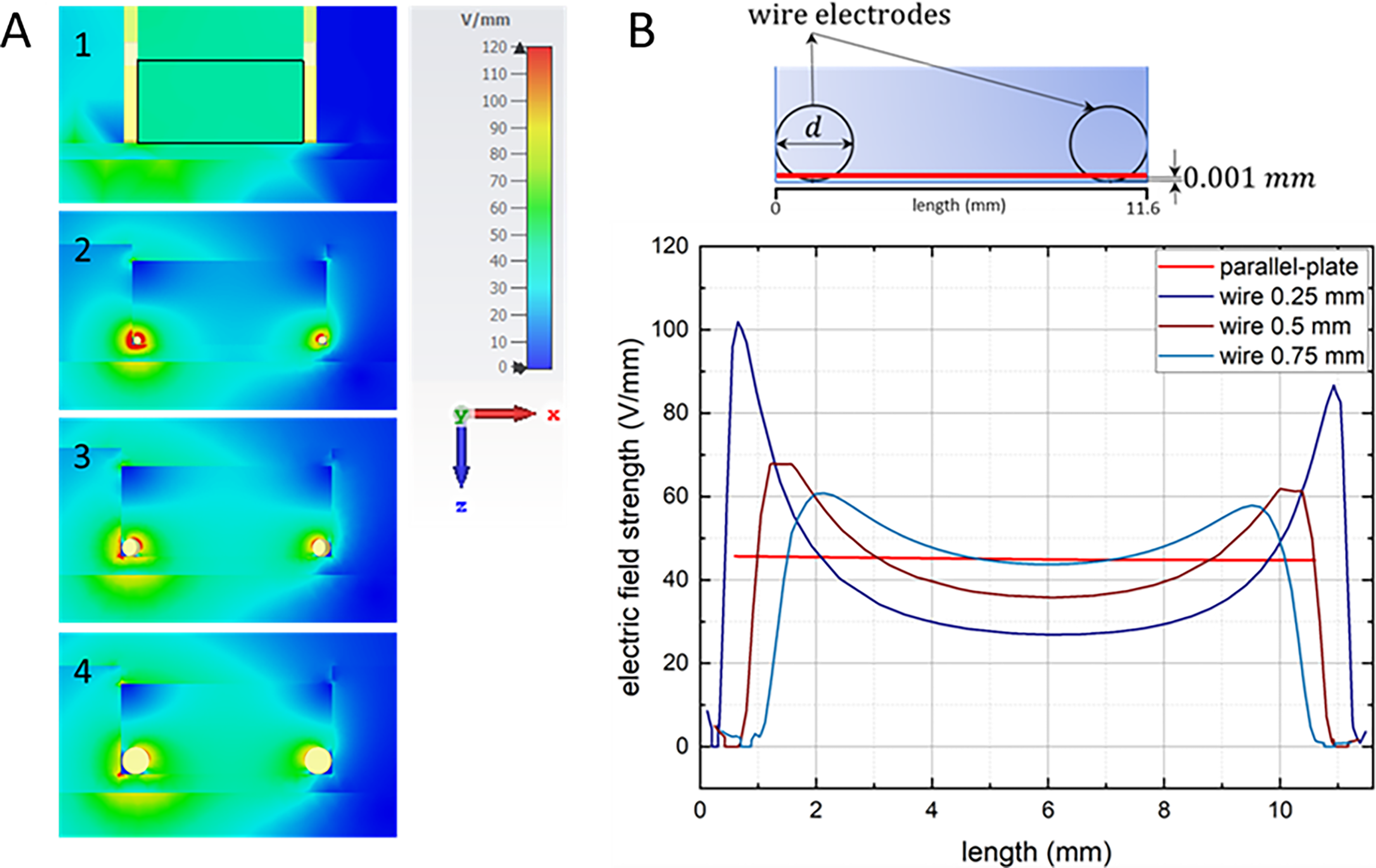
In the light of possible bulk analyses to be carried out to evaluate PEF exposure effects, such as qPCR or Western blot, it was of the utmost importance in our experimental context that all cells be exposed to the PEF treatment and, importantly, that they be exposed to the same EF amplitude. To meet these criteria, the simplest geometry for the treatment area would be a rectangular area delimited by the electrode set. Several designs of electrodes exist, such as plates, wires, or even metal meshes. 34 We explored the possibility of using pairs of wires or plates electrodes, already aware that in a 3D configuration, that is, in vivo, the EF distribution is more heterogeneous when using wire electrodes.35,36 We performed numerical simulations using CST Microwave Studio to know the EF distribution in the device when using either plate electrodes or wires of different diameters. Like in vivo, we found that the diameter of the wires has a large influence on the field distribution (Fig. 1). The most important issue is the fact that using wires, whatever their diameter, field amplitude at the bottom of the exposure chamber (where the attached cells are located) is very heterogenous. With wires, only a low percentage of cells will be exposed to an amplitude close to the voltage-to-distance ratio value (Fig. 1 and Table 1). On the contrary, with the use of plate electrodes, almost all the surface is exposed to the same field amplitude, which is identical to the voltage to distance ratio (Fig. 1 and Table 1). It is important to note that the use of a mask restricting the rectangular treated area (and thus the volume in which the current can circulate) and parallel plate electrodes fully covering two opposite faces results in the fact that there is no edge effect and that the field amplitude is really homogeneous.
Nominal Electric Fields and Percentages of Surface Exposed to the Nominal Electric Field ± 5 V/mm for Each Electrode Set Configuration
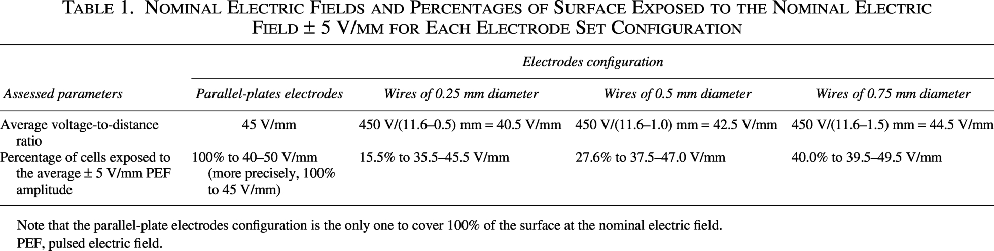
Note that the parallel-plate electrodes configuration is the only one to cover 100% of the surface at the nominal electric field.
PEF, pulsed electric field.
Electrochemistry and electrode material selection
A well-known issue associated with electrical stimulation, especially when conceived to be performed on a long-term basis, is the occurrence of irreversible electrochemical phenomena at the electrodes. Many different parameters acting in concert influence such phenomena, some of which directly relate to the electrical stimulation itself. In the context of the application presented in this paper, which uses PEF stimulation at relatively high voltages (though not as high as those used in conventional electroporation), this includes pulse length, amplitude, waveform, whether or not PEFs are bipolar and charge-balanced. 37
Other parameters influencing the occurrence of electrochemical phenomena are related to the conception of the exposure device, particularly the electrodes. The material and dimensions of the electrodes, along with the electrolyte, influence the stimulation device’s charge injection capacity, that is, the maximum amount of electrical charge an electrode can deliver reversibly. Noble metals, such as Platinum (Pt), Gold (Au), or alloys of Platinum and Iridium (Pt/Ir), exhibit very good performances as bioelectrodes, offering high conductivity and charge storage capacity, low impedance, and excellent corrosion resistance. 37 However, their high cost was a direct limitation in our study, given the choice of the plate electrodes configuration, for the purpose of a homogeneous EF distribution. Other metals or alloys are also commonly being used as electrode materials, such as Stainless Steel (SS) or Titanium (Ti). In PEF applications, SS is the most common electrode material.38,39 However, it is important to emphasize that most applications of high voltage PEFs, aimed at generating electroporation for medical or biological (in vitro) purposes, are usually brief treatments such as electrochemotherapy, irreversible electroporation, or gene electrotransfer. Moreover, in such applications, the electrodes are either intended for single use or can be re-passivated upon contact with oxygen in the air when not in use.40,41 Consequently, electrochemical phenomena in such contexts are less concerning than in the case of long-term electrostimulation, such as a neural stimulation. In the latter case, noble metals are typically preferred. 37 PEF treatments in food processing are also brief; however, they rely on devices designed for prolonged use. As such, concerns about electrochemical phenomena in PEF food processing parallel those of long-term stimulations with biomedical intents, and some common electrochemistry issues are relevant in both fields. The most common electrochemical phenomenon encountered is the occurrence of water electrolysis, which generates pH changes, formation of gas, and eventually bubbles, which subsequently cause uncertainty in the distribution of the EF, and therefore uncertainty about the efficacy of the treatment.37,42 Electrode dissolution through oxidative processes, transpassive corrosion, or pitting corrosion damages electrodes and releases metal into the electrolyte, which may have deleterious effects on cells, in vivo or in vitro.37,43 Finally, damage can also arise from oxidation of organic compounds. 37
The electrode-electrolyte interface is characterized by the formation of a double layer consisting of oriented dipoles and ions compensating for charge imbalance at the surface of the electrode. This double layer behaves as an electrical capacitor and is commonly referred to as the double-layer capacitor.44,45 If a potential difference is applied between two electrodes, a charge buildup across the double layer at the electrode-electrolyte interface takes place. The whole exposure system (the electrode-electrolyte interfaces and the bulk electrolyte) can be represented by equivalent electrical circuits which have been described in.
45
In the context of the application of PEFs, for which the potential difference applied across the exposure system largely exceeds the voltage building-up across the double layer, it appears that the time required to charge the double-layer capacitor up to critical voltage thresholds above which electrochemical reaction occurs can be expressed as follows44,45:

With tth, the time required to charge the double layer up to Uth, in seconds (s); Cdl, the capacitance of the double layer, in farads (F); i, the intensity of the current flowing in the mass of the electrolyte, in amperes (A); and Uth, a threshold voltage across the double layer above which electrochemical phenomena can occur, in volts (V) (typically between 1 and 2 V for most metals). 44
Equation 1 directly highlights the different parameters influencing whether or not electrochemical reactions can occur. In theory, as long as the duration of a pulse tpulse satisfies tpulse < tth, electrochemical phenomena should not occur. 45 Actually, the intensity of the current flowing through the electrolyte depends on the voltage applied across the exposure chamber and its geometry, and the capacitance of the double layer depends on the electrode material, dimensions, roughness, as well as on the electrolyte, and the threshold voltage depends on the electrode material.
Voltammetry monitoring can provide insights into the specific capacitance of given electrode materials. Such measurements were performed for SS and Ti at a scanning rate of 0.1 V/s in a 20 g/L NaCl aqueous solution at 20°C, yielding 35 and 50 µF/cm2, respectively. 46 At first glance, the capacitance of Ti seems more important than that of SS. However, it is important to note that roughness, which significantly impacts the capacitance,47,48 was not specified in this study. Nevertheless, Ti electrodes are gaining interest in the PEF food industry as less metal release tends to be observed in treated samples compared with SS electrodes.38,49–51 These observations align with preliminary experiments we conducted using SS electrodes that quickly deteriorated, a phenomenon that we did not observe with Ti electrodes subsequently.
Therefore, based on theoretical capacitance criteria, experimental observations from PEF food processing research, our own observations, and the high biocompatibility of Ti and its alloys,48,52–54 the choice of Ti electrodes appears strategic in terms of performance and cost in the context of our study.
A cell-culture-like system, which allows to perform microscopy during PEF exposure
We previously mentioned that the simplest geometry for the area of exposure to meet the criteria of our experimental context is a rectangular shape delimited by the set of plate electrodes.
Our first choice was an extremely simple set-up consisting in the use of commercial sets of four rectangular exposure chambers of 2 cm × 1 cm with a customized lid serving as a guide for the electrodes. However, we immediately encountered technical limitations with this system as we observed cell culture medium migrating from the wells to the cavities of the customized lid used as an electrode guide (as depicted by the red arrows in Fig. 2). This was due to capillarity building up in the narrow space between the electrodes and the walls of the wells of the rectangular exposure chambers. These leaks prevented any long-term follow-up and increased the risks of contamination.
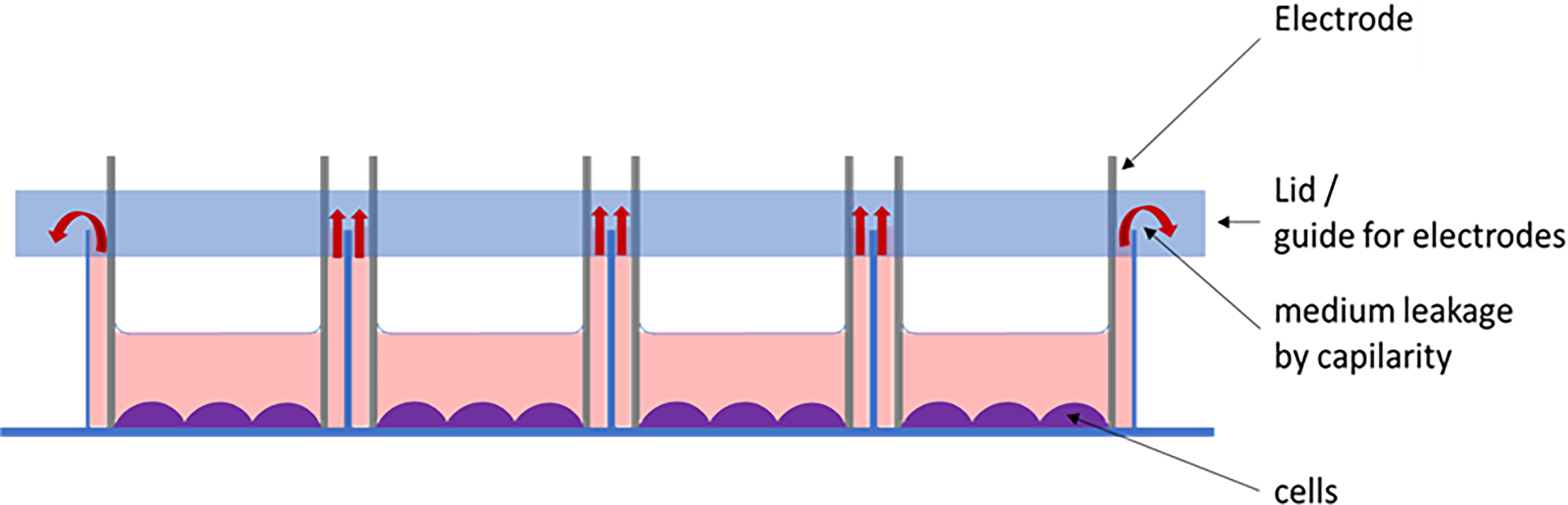
Scheme of the first exposure system used, which presented the major inconvenience of generating capillarity phenomena in the spaces comprised between the electrodes and the plastic walls of the chamber (red arrows).
To solve this problem, we needed a system whose geometry would not generate this issue yet ensure the exposure to the PEFs of the complete cell seeding area. We decided to design a system which would use very common laboratory material with the aim of making it easy to constitute. We chose regular Petri dishes (p35 in our context) in which we could define a rectangular cell seeding area by building masks made of PDMS, a biocompatible elastomer having very good dielectric properties 55 (Fig. 3).
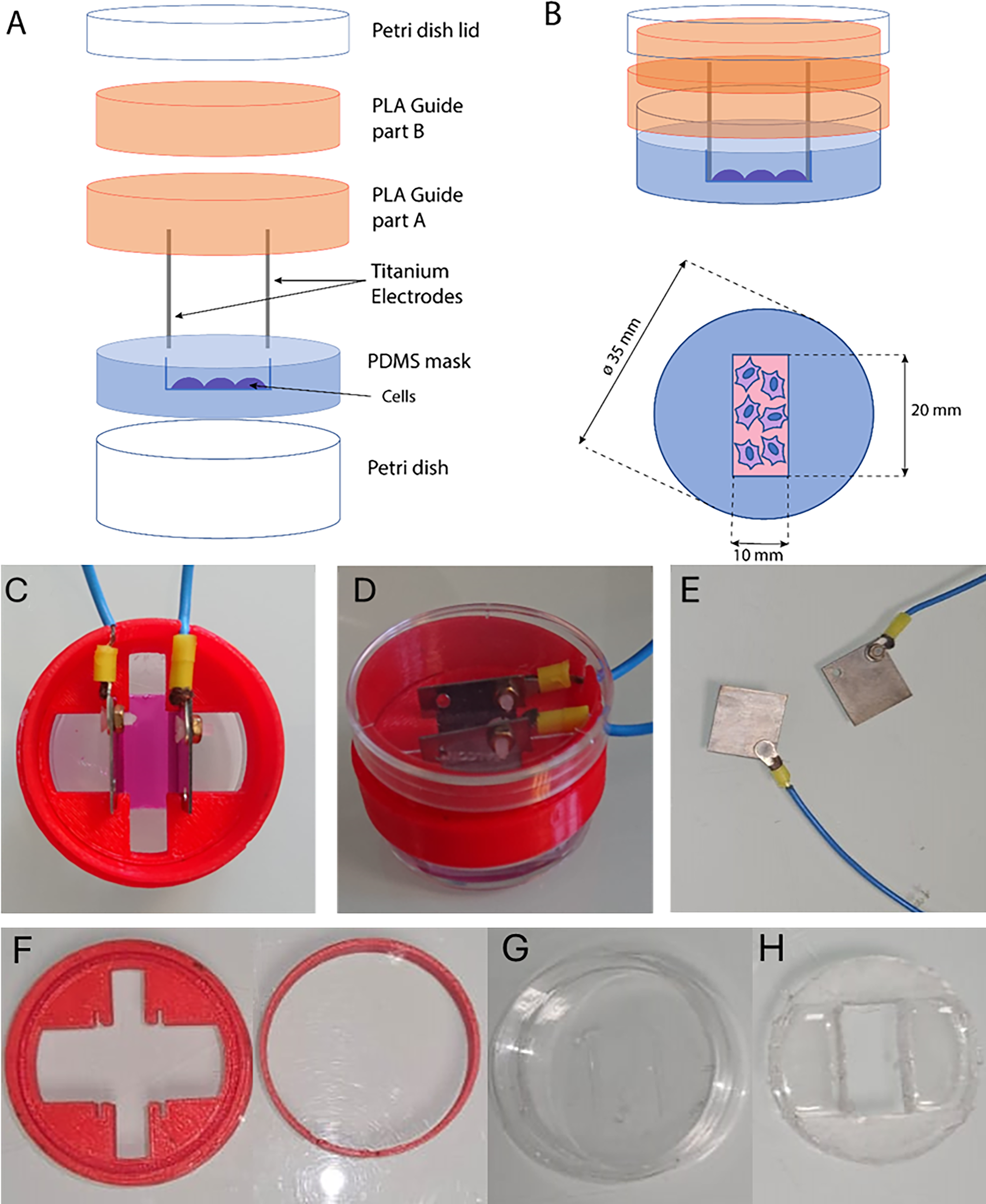
Scheme of the device,
The new device limited the evaporation, the capillarity, and the contamination risks. Long-term experiments could be initiated.
An example of the use of the device in the context of real-time imaging: bipolar µsPEFs can control calcium oscillations
We performed live experiments on MSCs from human adipose tissue, applying µsPEFs in a Ca2+ containing medium which allows Ca2+ entry from the cell outside, if the amplitude and duration of the pulse are sufficiently high. 56
MSCs are known to present asynchronous spontaneous Ca2+ oscillations that can be traced using the Ca2+ dye Fluo-4 AM (as well as the ones resulting from the application of a single µsPEF of appropriate field amplitude). With the device, it was possible to deliver the pulse and stimulate the cells inside the microscope cabinet, in which both the temperature and the CO2 were controlled. Microscopy acquisitions lasted 20 min. In this way, we could monitor the Ca2+ oscillations that occurred before and immediately after the pulse.
To limit as much as possible electrochemical effects in long-term stimulations, besides the selection of the electrode material, we investigated the modulation of the Ca2+ oscillations using bipolar pulses instead of the previously used 100 µs monopolar pulses.57,58 For that purpose, we selected a pulse condition that was shown in previous studies to produce a calcium response in these same cells: 100 µs of pulse duration and 450 V/cm12 and we compared its effect to those of one “50 + 50” bipolar µsPEF (50 µs in positive polarity + 50 µs in negative polarity, with a total duration of 100 µs) at 450 V/cm, or of one “100 + 100” bipolar µsPEF (100 µs in positive polarity + 100 µs in negative polarity, with a total duration of 200 µs) at 450 V/cm.
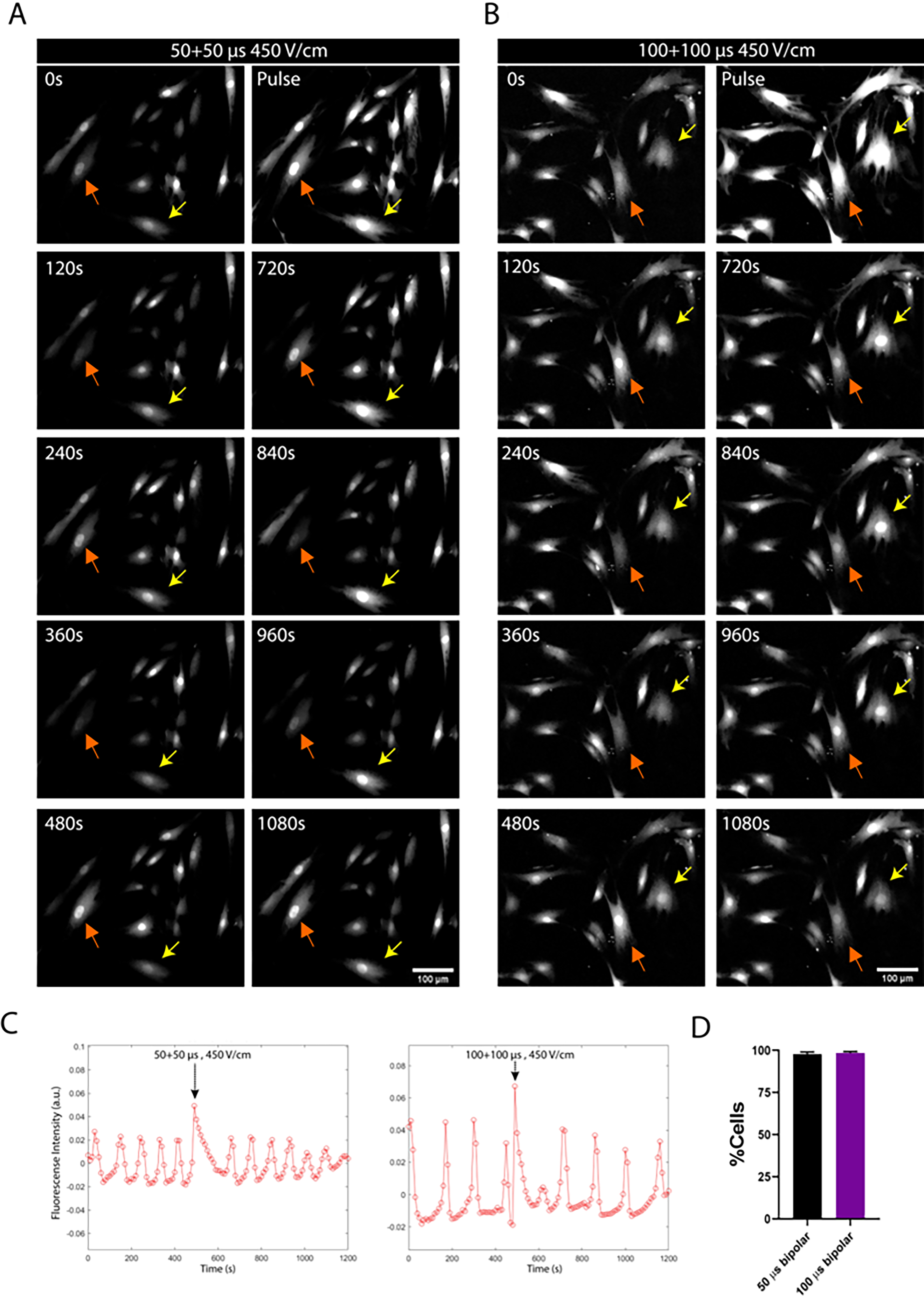
Using the device, we could record the MSCs exhibiting spontaneous asynchronous calcium oscillations. When MSCs were subjected to one pulse, either 50 + 50 or 100 + 100 bipolar, most cells exhibited a massive calcium influx (Fig. 4A,B; pulse), whose shape was somehow different from those of natural oscillations (Fig. 4C). Regardless of the pulse duration (50 + 50 µs, or 100 + 100 µs), both pulses added a spike with an amplitude greater than the normal oscillation in almost 100% of cells (Fig. 4D), meaning that the bipolar stimulations are able to modulate calcium oscillations in MSCs like the monopolar pulses previously used in. 12
We also compared the ability of these bipolar pulses to inhibit the natural Ca2+ oscillations after the induction of an important Ca2+ oscillation, as it can occur with the use of monopolar pulses as previously described. 12 The inhibition of the Ca2+ oscillations could be classified in two categories, inhibition for less than 10 min (short inhibition) (Fig. 5B) or for more than 10 min (long inhibition) (Fig. 5C). A third category included the cells whose natural Ca2+ oscillations were not inhibited (Fig. 5A). Although there were no significant differences in the percentage of cells that exhibited a Ca2+ oscillation in response to either one 50 + 50 µs or one 100 + 100 µs at 450 V/cm (Fig. 4D), the effects varied in terms of inhibition of the natural Ca2+ oscillations of the MSCs. Compared to the delivery of one 100 + 100 µs pulse, more cells continued to display immediately their natural Ca2+ oscillations after the application of one 50 + 50 µs pulse (Fig. 5A), less cells displayed a short inhibition (Fig. 5B), while no significant difference in the percentage of cells showing long inhibition (more than 10 min) was found (Fig. 5C).
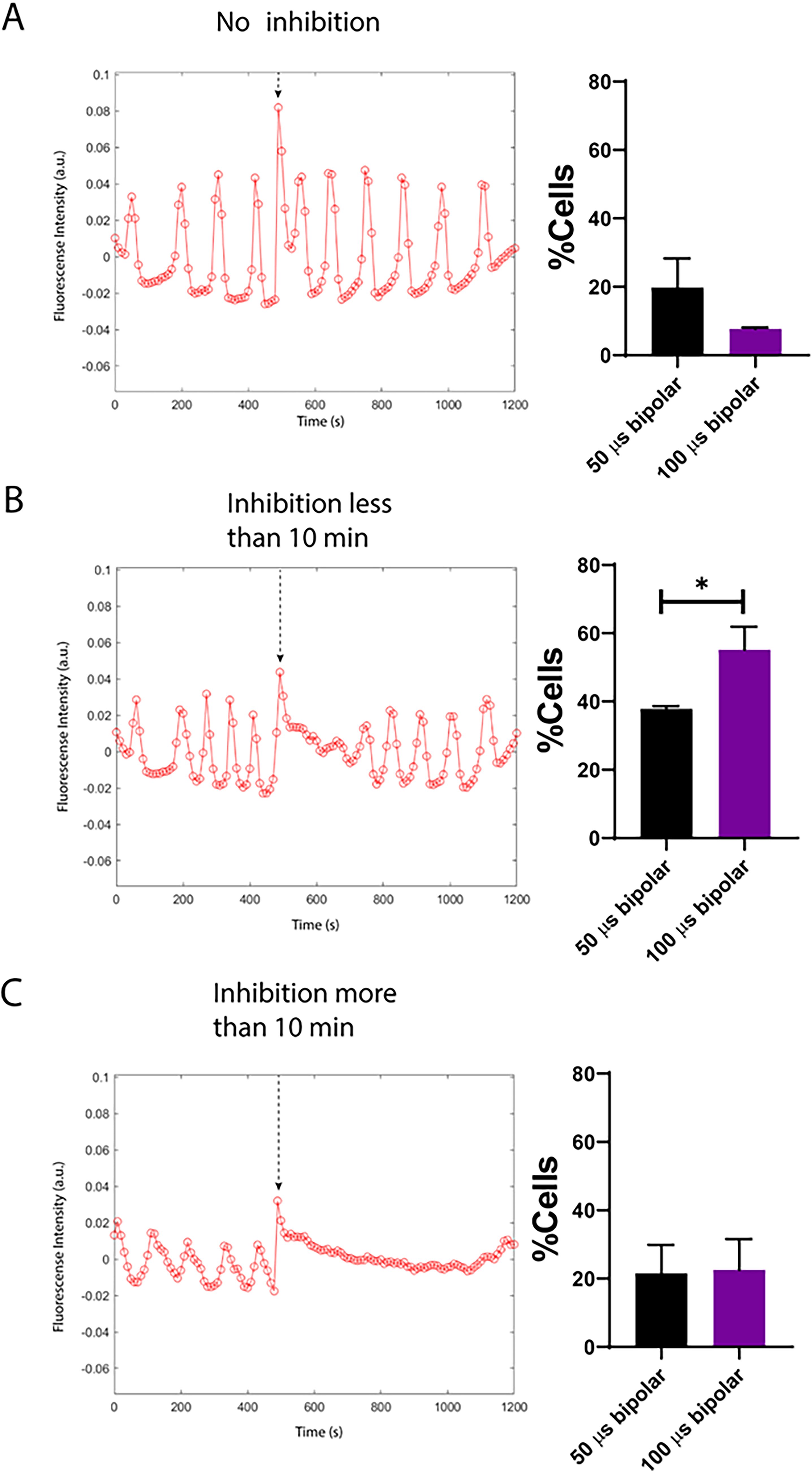
Inhibition of Ca2+ oscillations after the application of one single 50 + 50 µs or 100 + 100 µs pulse at 450 V/cm. Three different outcomes can be observed, either no inhibition of the natural Ca2+ oscillations after the important Ca2+ spike generated
Short inhibition and long inhibition of Ca2+ oscillations might subsequently have distinct biological outcomes. Indeed, it was previously reported that after an inhibition of Ca2+ oscillations for at least 10 min (long inhibition), cell cycle and ERK/MAPK cascades can be affected.59,60 Also, the calcium oscillation frequency of MSCs decreases, while the differentiation process of MSCs progresses.5,61,62 We have shown here that both the 50 + 50 µs and the 100 + 100 µs bipolar pulses achieve the same percentage of cells with long inhibition that the percentage previously achieved after one monopolar 100 µs monopolar pulse, 12 meaning that we could reach the same long inhibition of Ca2+ oscillations with a stimulation more suitable for long-term uses.
The device suits long-term exposure of cells to the PEFs
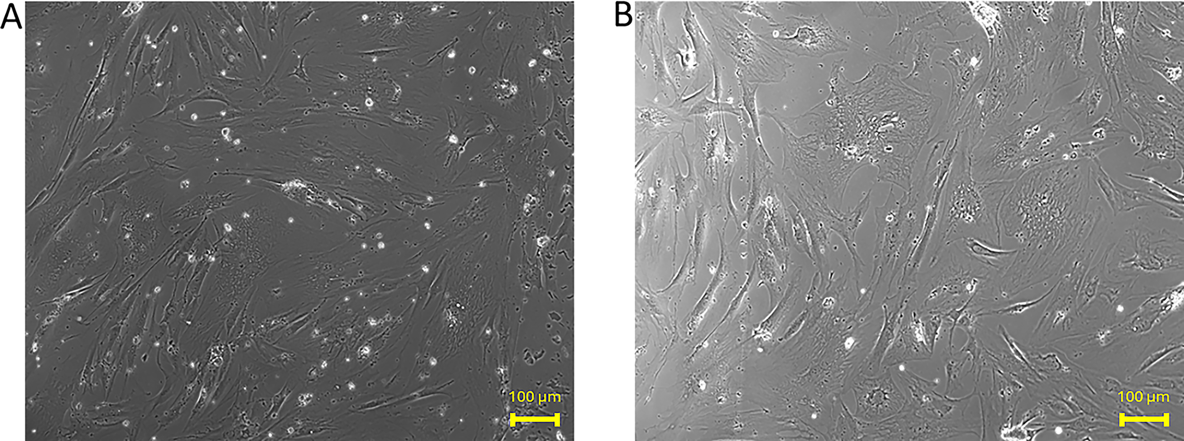
Following the optimization reported for the use of bipolar pulses instead of monopolar pulses, as part of the effort in reducing the risk of electrochemical effects at the electrodes, we started to perform long-term exposures, with repetitive cycles of PEFs over several days. Figure 6 shows that after 5 days of exposure to bipolar PEFs at 300 V/cm, the cells still look healthy (Fig. 6B), with similar morphologies as compared with the control MSCs (Fig. 6A). Actually, cells treated with such bipolar µsPEFs can even proliferate better than control cells under some conditions. 62 Taken together, these elements show that the device, along with the type of electrical stimulation, are suitable for the use in long-term stimulations.
Conclusion
We propose a device for the long-term electrical stimulation of cells in culture, constituted of classical Petri dishes in which a biocompatible PDMS mask system 55 defines the area of cell seeding. This allows to maintain the sterility in the same way than in regular cell culture conditions. The electrodes are made of grade 2 titanium, a material of choice for limiting electrochemical reactions. The electrode configuration selected is a pair of facing parallel plate electrodes to ensure the homogeneity of the EF applied over the whole of the cell seeding area, as demonstrated here in comparison to other possible geometries. The electrodes are guided with a 3D-printed PLA guide, designed to fit both the lower part and the lid of the Petri dish. Overall, the entire device is easy to produce, easy to assemble, reliable in long-term experiments, and cost-effective. Moreover, the device also allows accurate, unbiased microscopy observations between or even during cell electrical stimulations.
In this article, we also illustrate the use of this device in the context of controlling the Ca2+ oscillations in MSCs with µsPEFs of characteristics compatible with long-term experiments. We also report its use in microscopy experiments that can be performed while simultaneously delivering µsPEFs. Indeed, the use of the device described in this article has shown good performances for electrical stimulations while recording Ca2+ oscillations in MSCs at the microscope with no inconvenience. No capillarity nor sterility problems were observed on the long-term use of the device. The device presented here is based on dimensions suiting the requirements of our previous studies on calcium oscillations to validate both the previous work and the optimized design of the device. Any dimension adaptation is possible to suit any other experimental design, as long as it remains safe regarding electrochemical phenomena, using bigger or smaller Petri dishes, following the same rationale, namely, to build a system in which the electrodes can be very easily removed from the cell treatment chamber when the electric treatment ends, and that preserves the chamber sterility and reduces electrochemical reactions.
Ethics Approval and Consent to Participate
The human-adipose-derived MSCs used in this study were surgical wastes and, as such, the French law Art.L. 1245-2 du Code de la Santé Publique established that there was no need to receive the authorization from an ethics committee.
Authors’ Contributions
L.A.V.: Conceptualization, formal analysis, investigation, methodology, software, visualization, writing—original draft, and writing—review and editing. M.S.-P.: Conceptualization, formal analysis, investigation, methodology, software, visualization, writing—original draft, and writing—review and editing. N.I.: Formal analysis, resources, methodology, software, visualization, and writing—original draft. R.F.: Investigation. NN: Formal analysis, investigation, visualization, and writing—original draft. A.M.G.-A.: Resources and software. F.M.A.: Conceptualization, resources, methodology, validation, visualization, and writing—original draft. L.M.M.: Conceptualization, formal analysis, funding acquisition, investigation, methodology, supervision, validation, visualization, writing—original draft, and writing—review and editing.
Supplemental Material
sj-docx-1-bie-10.1177_25763113261460786 — Supplemental material for A Device to Ensure In Vitro Controlled and Sustained Cells Exposure to Electrical Stimulations: The Example of Calcium Oscillations Control in Mesenchymal Stem Cells with Microsecond Pulsed Electric Fields
Supplemental material, sj-docx-1-bie-10.1177_25763113261460786 for A Device to Ensure In Vitro Controlled and Sustained Cells Exposure to Electrical Stimulations: The Example of Calcium Oscillations Control in Mesenchymal Stem Cells with Microsecond Pulsed Electric Fields by Leslie A. Vallet, Marina Sanchez-Petidier, Njomza Leduc, Romain Fernandes, Adrian Martínez Gómez-Aldaraví, Nataliia Naumova, Franck M. Andre, and Lluis M. Mir
Footnotes
Acknowledgments
The authors would like to thank Dr. Bassim Al Sakere for the lipoaspirates. N.N. would like to thank the support of the PAUSE program. For the purpose of Open Access, a Creative Commons Attribution (CC BY) public copyright license has been applied by the authors to the present document and will be applied to all subsequent versions up to the Author Accepted Article arising from this submission.
Author Disclosure Statement
The authors have no competing interests to declare.
Funding Information
This research was funded by CNRS, Gustave Roussy, Université Paris-Saclay, and by the FET-OPEN H2020, grant number 964562. M.S.-P. would like to thank the Spanish Ministry of Science and Innovation for the grant JDC2022-049856-I, cofunded by the European Union NextGenerationEU/PRTR.
References
Supplementary Material
Please find the following supplemental material available below.
For Open Access articles published under a Creative Commons License, all supplemental material carries the same license as the article it is associated with.
For non-Open Access articles published, all supplemental material carries a non-exclusive license, and permission requests for re-use of supplemental material or any part of supplemental material shall be sent directly to the copyright owner as specified in the copyright notice associated with the article.
