
Abstract
The term “gel” refers to any small defect that distorts a film product. Eliminating gel defects from extruded polyethylene film products can be difficult, time consuming, and expensive due to the problem's complexity and the off-specification product produced. This paper discusses how to: identify gel types, common root causes, and technical solutions for mitigating gels in film products produced using single-screw extruders.
Introduction
Troubleshooting extrusion processes where gels appear in polyethylene (PE) film products can be difficult due to the different gel types that are possible. For these processes, the troubleshooter must diagnose the problem quickly and provide an economically viable technical solution. 1 Because gels originate from numerous sources, the troubleshooter must identify the gel characteristics and recognize the likely cause. Then the process is changed to mitigate the gel defects.
There are many types of gels
2
and the most common include:
highly oxidized polymeric materials that appear as brittle black specks, polymeric materials that are crosslinked via an oxidative process, highly-entangled polymeric material (such as high molecular weight species) that are undispersed and not crosslinked, unmelted resin or solid polymer fragments, filler agglomerates from masterbatches, a different resin or contaminant such as metal, wood, cloth fibers, insects, or dirt.
A crosslinked resin gel is typically formed during an oxidation process, resulting in crosslinked resin chains and discolored gels.
Highly-entangled gels are typically entangled high-molecular-weight polymer chains that are difficult to disperse during the extrusion process. When analyzed using a hot-stage microscope, this gel type will melt as the stage temperature is increased. When the stage temperature is then decreased, the gel will recrystallize, creating the appearance of a gel as a solid polymer fragment. If the gel is exposed to a shear stress right after melting, the stress will often disentangle the chains such that they will not reform when cooled. Since these gels are not oxidized they are not associated with color. They are commonly referred to as undispersed or unmixed gels.
Unmelted resin exiting with the discharge can sometimes occur, especially at high extrusion rates. These gels will melt during heating on a hot-stage microscope, and typically they will not reform during the cooling phase.
Numerous sophisticated methods are available for analyzing gels including epi-fluorescence microscopy, polarized light microscopy, and scanning electron microscopy with X-ray microanalysis. These methods are discussed in the next sections.
Gels can be generated from many different sources and include:
the resin manufacturer, the converting process, pellet blending resins with significantly different shear viscosities, pellet blending different resin types, direct contamination.
Modern resin-manufacturing processes exclude oxygen from the system and are very streamlined such that process areas with long residence times do not exist. As such, crosslinked and oxidative gels are likely not generated by the manufacturer. Improperly designed extrusion equipment and processes, however, are common, leading to oxidative degradation and crosslinked gels. Several case studies in the next sections show how poorly designed processing equipment can lead to film products with crosslinked and unmixed gel contamination.
The goal of this paper is to describe: the gels that are likely to occur in PE film products, techniques for identifying the gel type and technical solutions to mitigate them from single-screw extrusion processes. Several case studies will be provided that show the strategy for mitigating gels.
Protocols for gel analysis
Established protocols for gel analysis in polymer films are well documented in the literature.2–4 Figure 1 shows how to identify gels.
4
Typically, a film with defects is visually inspected using a low-power dissecting microscope. The gels are classified based on size, color, and shape, and isolated using a razor blade or scissors. Cross sections 5- to 10-µm thick are collected below the film glass transition temperature (Tg) using a cryogenic microtome; i.e. −80℃ to −120℃. For optical examination, a thin section containing the gels is placed on a glass microscope slide with a drop of silicon oil and covered with a glass cover slip. Additional sections are collected for hot-stage microscopy and for compositional identification if needed.
Methodology for characterizing defects in polymer films.
4
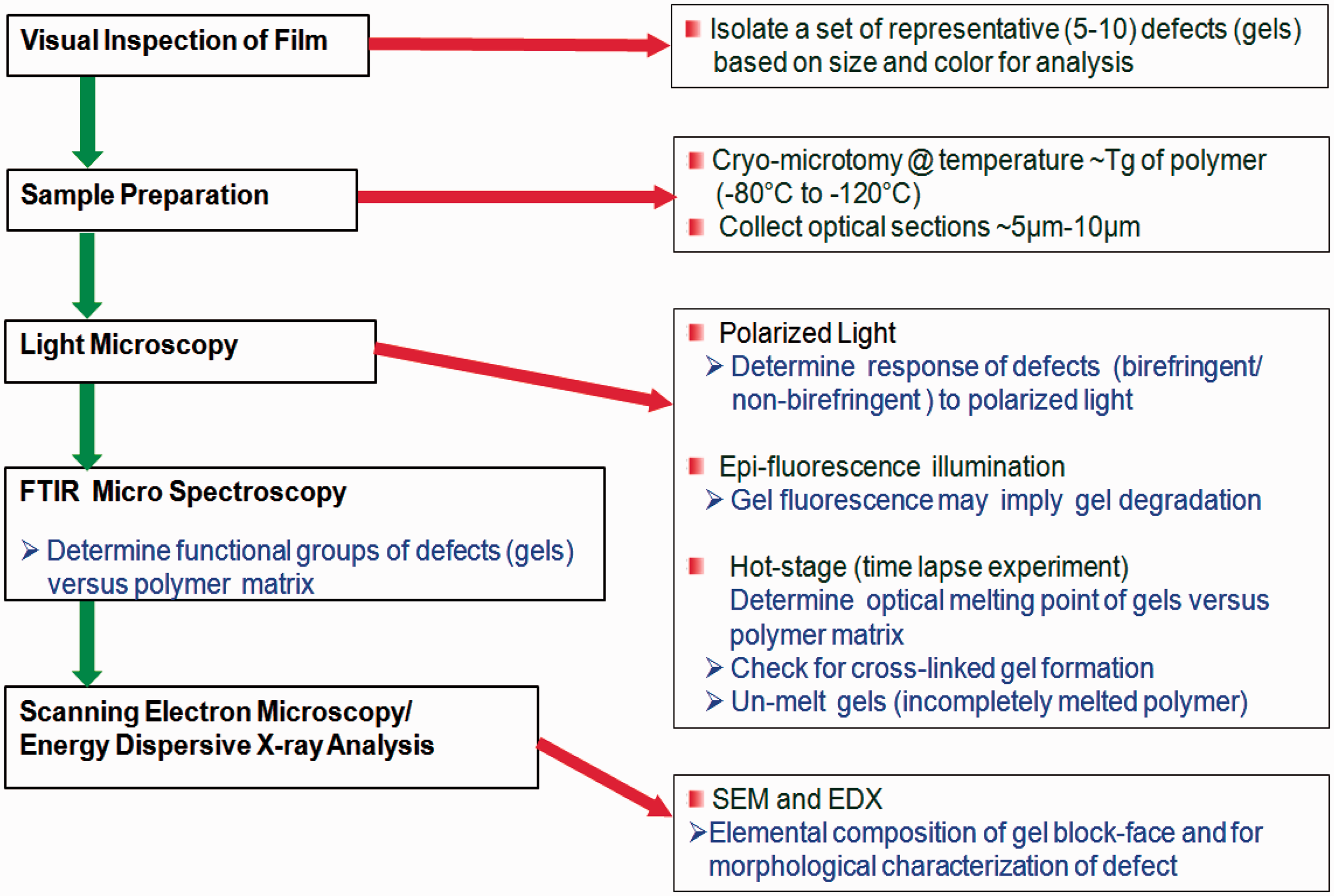
After collecting the sections, the remaining polished block-face containing the remainder of the gel is retained. In many instances, gels arise from inorganic contaminants such as the metallurgy from pellet handling equipment, extruders, or components from masterbatches. Examining these inorganic components is best performed with the block-face sample using a scanning electron microscope (SEM) equipped with an energy dispersive X-ray detector (EDX).5,6 In some cases, additives or inorganic residues are present in low concentrations within the gels. A method to enrich the concentration of these materials is to expose the block-face containing the gel to oxygen plasma. Etching will preferentially remove the polymer at a much faster rate than the inorganic materials, enriching the inorganic components for elemental analyses. It must be noted that prior to SEM and EDX analyses, a thin conductive coating like carbon is typically evaporated onto the sample to render it conductive under the electron beam.
The next sections describe ways to analyze common gel types.
Oxidized gels
The most common gel is caused by oxidative processes that crosslink the PE chains. The best way to identify this gel is to observe them with polarized light and ultraviolet (UV) light sources. Transmitted polarized light microscopy is an effective technique
7
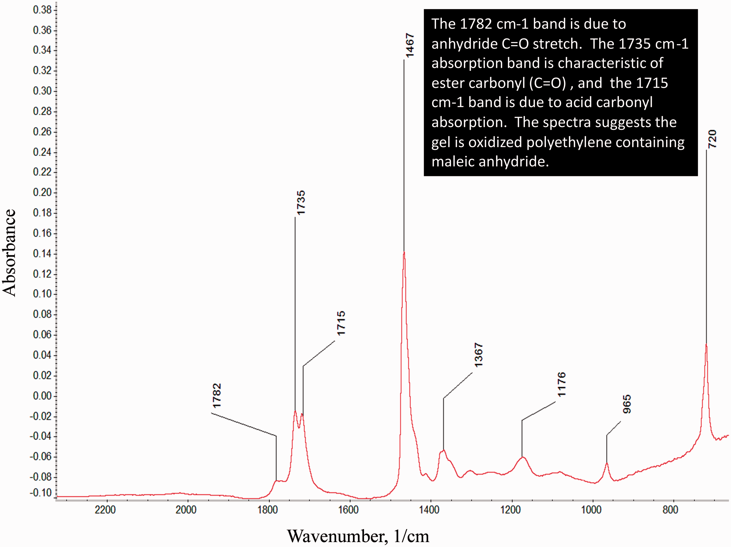
for investigating structures in crystalline films. For example, black speck gels were contaminating a multilayer film product. The gels were relatively brittle when cut for analysis. The source was unknown. Figure 2(a) shows the gel using transmitted polarized light. Figure 2(b) shows an intense fluorescence emission using epi-fluorescence with an UV light source. This emission suggests thermal oxidation and polymer crosslinking. Micro-infrared analysis indicated that the gel contained oxidized PE and maleic anhydride (Figure 3). This material likely formed on the extruder metal surfaces and then flaked off during a minor process instability. The material then flowed downstream and contaminated the film as a gel.
Transmitted polarized light images of a thermally oxidized and crosslinked gel in a multilayer film: (a) photograph in polarized light and (b) the gel fluorescing under ultraviolet (UV) light. The micro-infrared spectrum of gel shown in Figure 2. The spectrum suggests it is an oxidized polyethylene (PE) gel containing maleic anhydride.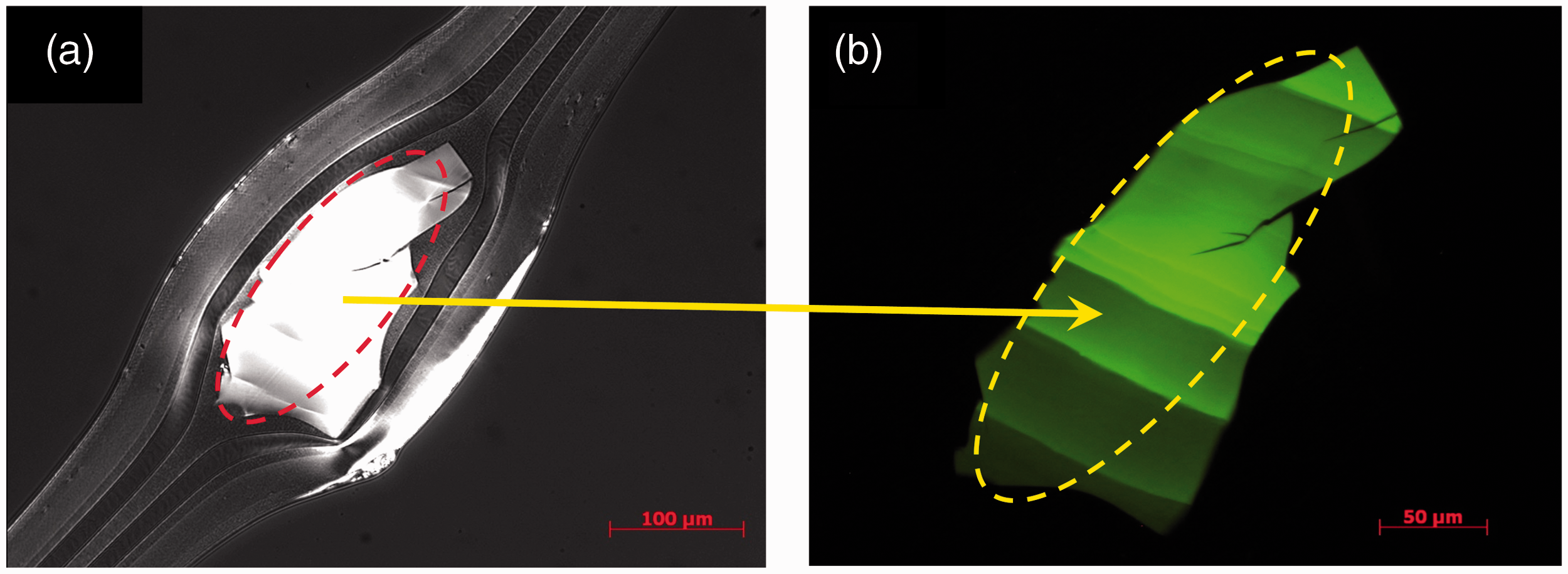
Crosslinked gels
Crosslinked gels are oxidized gels, where the oxidation level may not be enough to cause them to fluoresce under UV light. These gels may have some crystallinity and thus be birefringent under polarized light. For example, Figure 4(a) shows a slightly birefringent gel studied using a temperature programmable hot stage, polarizing light microscope.
7
The gel optical melting temperature (Tm) was 128℃ and consistent with the PE used (Figure 4(b)). To determine if the gel was unmixed (highly entangled and not crosslinked), the gel was held above the melting temperature (135℃) and then stressed. A dental tool was used to stress the glass cover slip. Crosslinked gels will appear birefringent (Figure 4(c)), in response to the anisotropy of stress distribution in the gel to polarized light. The gel dimensions and shape remained after cooling verifying crosslinking, (Figure 4(d)). If the gel was highly entangled and not crosslinked, the gel would disappear after the stress and cooling were applied.
Hot-stage microscopy of a crosslinked gel in a crystalline monolayer film: (a) below the melting temperature, (b) optical melting point at 128℃, (c) appearance of birefringence after stressing at 135℃, and (d) intact crosslinked gel after cooling to 30℃.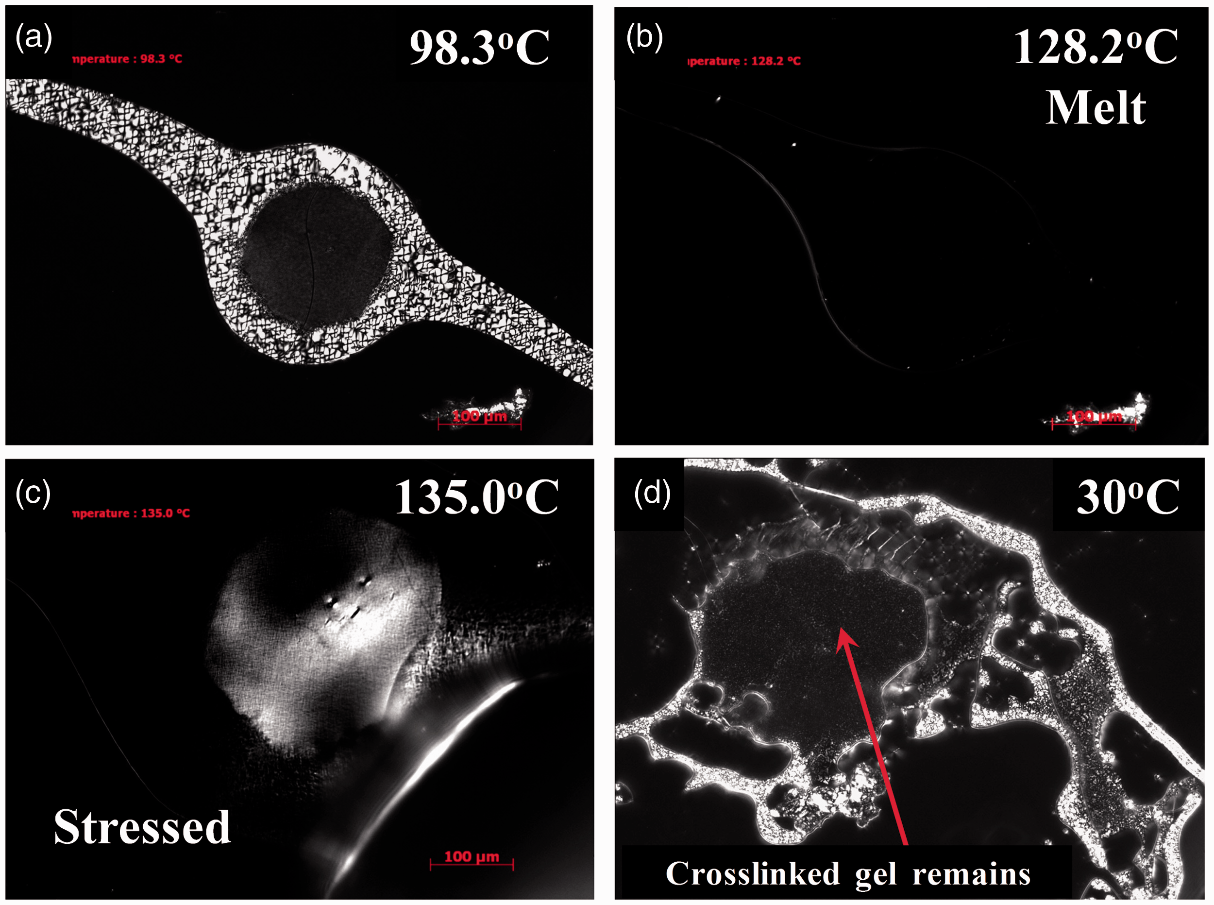
Solid polymer fragments in film and pipe
Resin degradation and solid polymer fragments that did not melt during the extrusion process typically cause blemishes in films and thin-walled pipe products. Solid polymer fragments appear as “windows” when the pipe wall is cross-sectioned to inspect the unmelts. Figure 5 shows photographs of these solid polymer fragments. Here the feed for this thin wall pipe was a high-density PE (HDPE) resin and a black tinted masterbatch using a grooved-bore extruder. The solid HDPE polymer fragments cause the windows. Since this natural pellet did not melt and disperse in the extruder, it contained no black pigment from the masterbatch. The solid polymer fragments in this case caused small pin holes to occur in the thin-wall pipe. Solid polymer fragments can also occur in sheet products.
Photographs of solid polymer fragments that occurred in thin-walled, high-density polyethylene (HDPE) pipe. The feedstock was a natural resin and a black-colored masterbatch.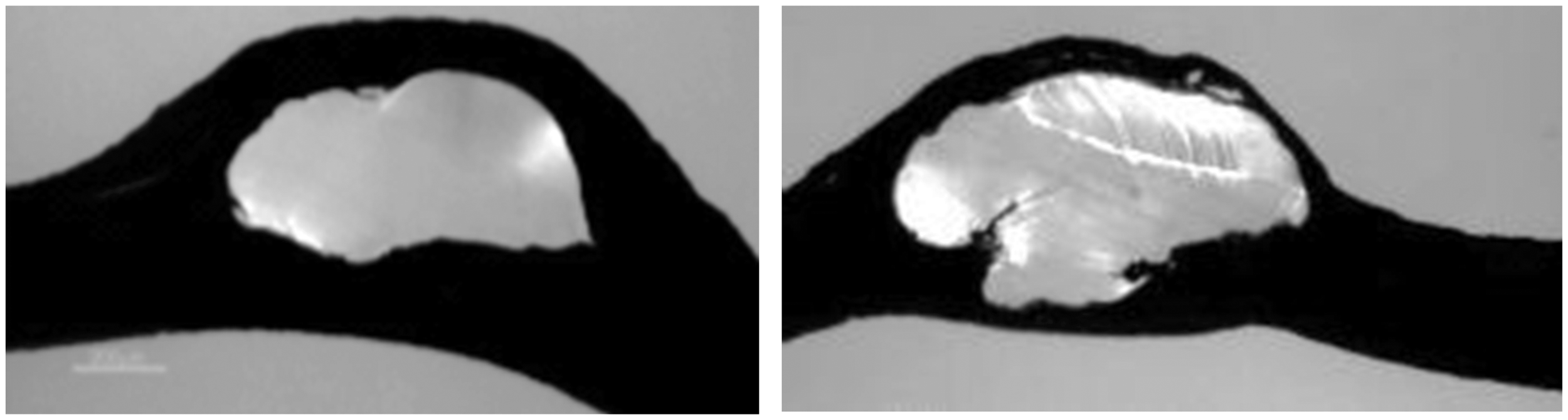
On numerous occasions, a processor will switch from a natural PE resin plus a black masterbatch (or another color) to a pre-compounded black PE resin. The switch is made as a solution to eliminate windows from the pipe wall. No other changes to the process are typically made. The processor typically does not complain about solid polymer fragments with the pre-compounded resin although they are likely present in the pipe. Since the fragments are black like the surrounding resin, they cannot be visually detected. When the natural resin and black masterbatch are extruded, natural solid polymer fragments are easily observed in a black tinted matrix. Solid fragments from the masterbatch would not be visually detected although they are also likely present.
Gels from foreign contamination
The origin of defects causing discoloration in PE pellets can be identified using light and electron microscopy. For example, PE pellets from an in-plant recycle re-pelletizing process contained some pellets that were off color and had black specks (Figure 6(a)). One defect was isolated via cross sectioning (Figure 6(b)). The cross section revealed an intense reddish particle that caused the pellet discoloration.
Photographs of foreign contamination in pellets of a re-pelletized reclaim stream: (a) photomicrograph of discolored polyethylene (PE) pellets containing dark defects and (b) transmitted polarized light micrograph of a pellet cross section containing a defect.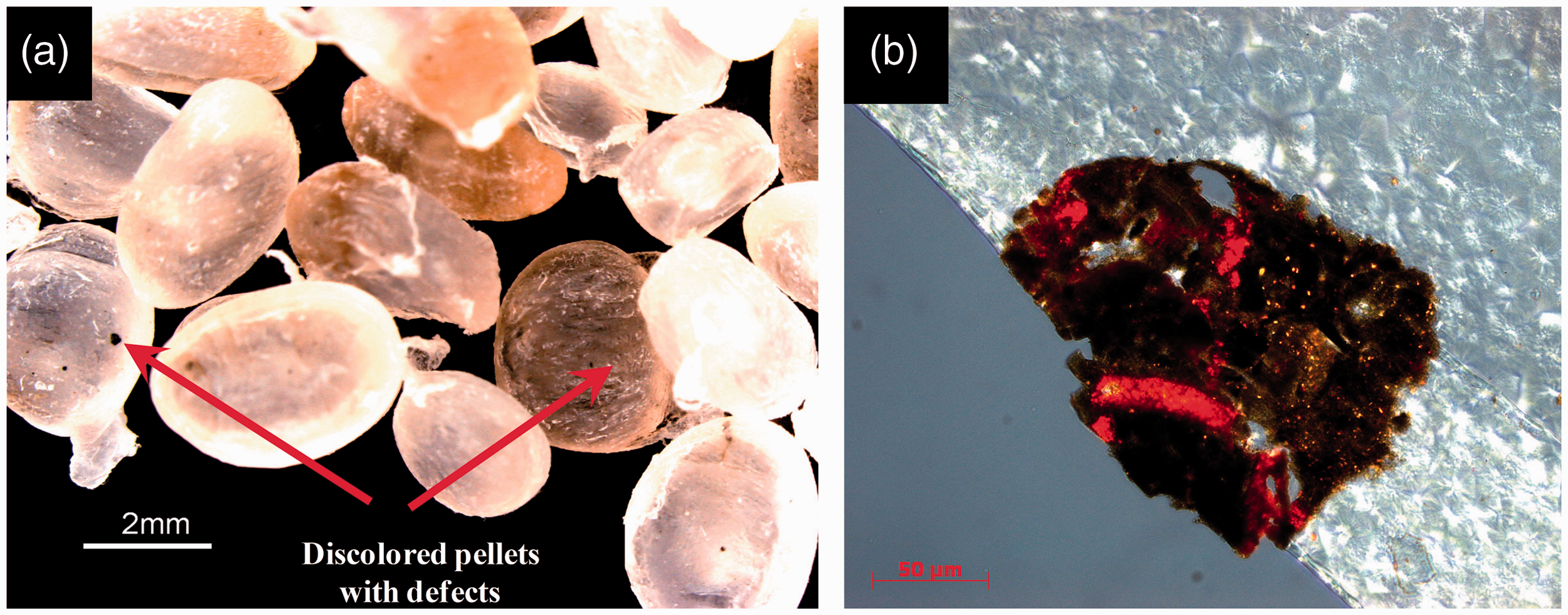
SEM and EDX microanalysis determined that the defects contained primarily iron and oxygen, and the contaminant was likely iron oxide. Figure 7 shows a backscatter electron image (BEI) of the pellet block-face sample showing the defect causing the discoloration and the elemental spectrum. Metallic-based defects can originate from process equipment, railcars used for shipment, pellet transfer lines, and poor housekeeping. The iron oxide was likely from a storage bin.
Energy dispersive X-ray detector (EDX) microanalysis of an inclusion in a polyethylene (PE) pellet cross section (Figure 6(b)). The analysis indicated that the particle was likely iron oxide.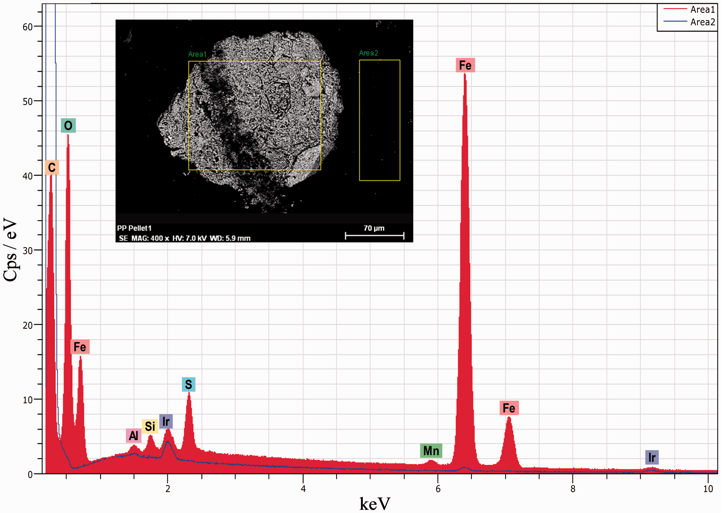
In another example, a multilayer film product was experiencing occasional gels. The gels were isolated and then cross sectioned (Figure 8(a)). These gels contained highly birefringent particles that resided in the core layer. The outer film layers appeared amorphous and the core layer was slightly birefringent. The core layer melted at 126℃ and the birefringent gels melted at 265℃. The 126℃ melting temperature was consistent with the PE resin used to produce the core layer. The higher melting temperature material and micro-infrared analyses of the defects indicate that they were foreign contaminants, and they were identified as a polyester resin. The polyester resin was used in another process in the converting plant, and it inadvertently contaminated the PE feedstock.
Photographs of gels in the core layer of a three-layer film: (a) transmitted polarized light and (b) hot-stage microscopy was used to determine the core resin and defect melting temperatures.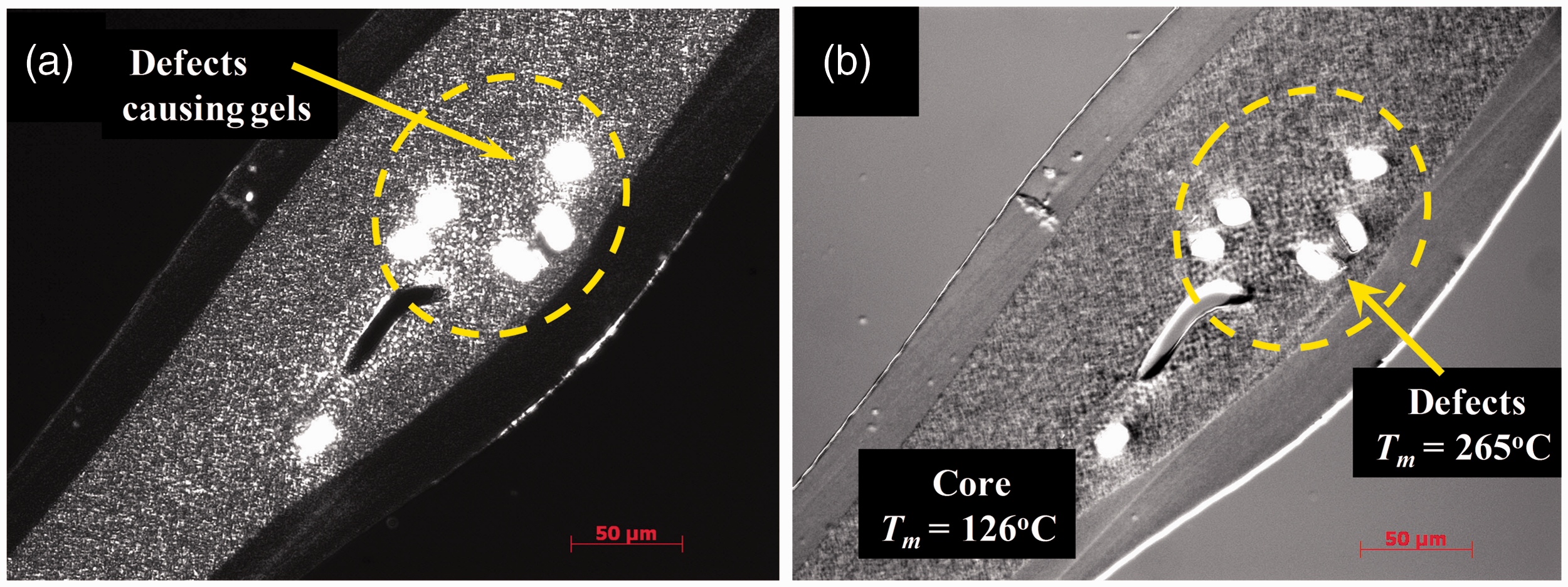
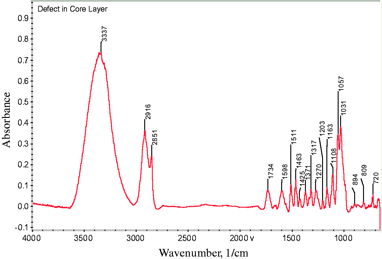
Another common contaminant that produces gels is fibers (Figure 9). In many cases, these contaminants are cotton fibers from clothing and gloves or cellulosic fibers from packaging materials. Fourier transform infrared (FTIR) spectroscopy is a great technique to determine the chemical functionality of organic-based defects in PE films. FTIR spectroscopy provides the infrared absorbance characteristics for the defect (Figure 10). The broad absorption bands near 3600 cm−1 to 3100 cm−1 are due to hydroxyl (–OH) stretching vibrations, the C-H vibration stretch is near 2916 cm−1 to 2851 cm−1, and the ester carbonyl group absorption is near 1734 cm−1. These infrared absorption characteristics suggest that the defect is a cellulosic fiber with degraded PE resin.
Transmitted bright-field image of polyethylene (PE) film containing a fibrous gel. Fourier transform infrared (FTIR) spectrum of defect in a polyethylene (PE) film. The spectrum indicates that the gel (Figure 9) is a cellulosic fiber and degraded PE resin.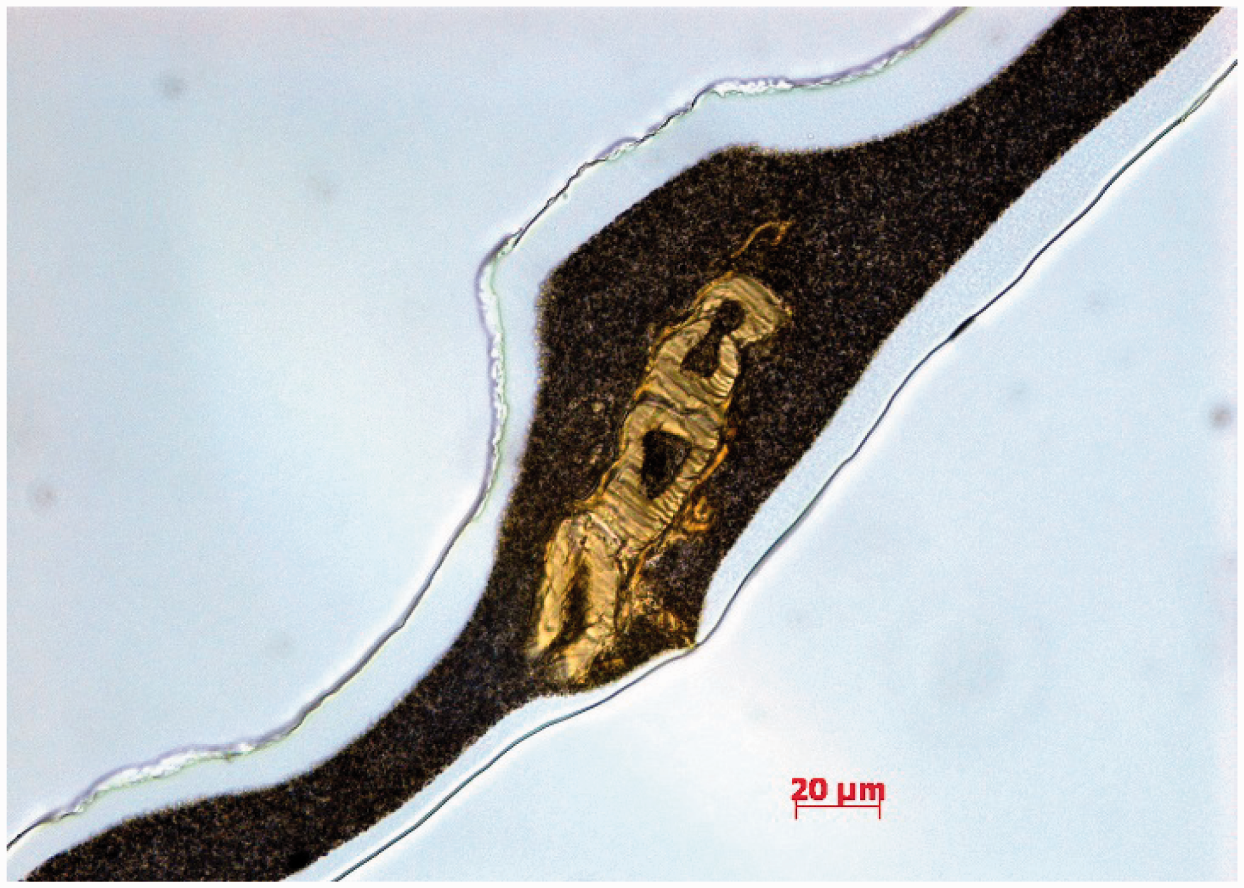
Once the contaminant is identified, the troubleshooter must determine how the material entered the feedstock stream. Process controls must be identified and implemented to mitigate the contaminant source.
Locating regions on the screw where resin degradation occurs
If the gel analysis indicates that the defects are due to degraded resin, then the best way to locate the region on the screw where the degradation is occurring is to remove the screw from the extruder while hot. For this procedure, pellet flow to the hopper is stopped while screw rotation is continued. The screw is rotated until resin flow out of the die stops. Next, screw rotation is stopped and the transfer line is removed from the discharge end of the extruder. The hot screw should be pushed out about three diameters and then photographed and studied for indications of resin degradation. The metal surfaces should appear clean with only mild discoloration. If a stagnant region exits, then dark-colored, degraded material will occupy the space. Once the segment is studied and photographed, the hot resin should be removed from the screw using brass tools. Another three diameters are then pushed out and the process is repeated. If the process is running a natural resin and a colored masterbatch, the extruder should be first purged with the natural resin until the extrudate is essentially colorant free.
Case studies
Oxidized gels and carbon specks can be created inside the extrusion processing line, and unmixed gels and solid polymer fragments can be released to the extrudate. Crosslinked gels and black specks occur due to regions in the process that are stagnant and have very long residence times in the extruder. Unmixed gels and solid polymer fragments occur because the resin was not subjected to a high stress level during processing. This section provides several case studies where these gels occurred. The technical solutions to mitigate the gels are then presented.
Gel showers in a cast film process
Crosslinked gels can form in stagnant regions in screw channels, transfer lines, and dies. These gels to form in about 30 min for linear low-density PE (LLDPE) resin and up to 12 days for low-density PE (LDPE) resin. Stagnant regions can occur at entries and exits of mixers 1 and barrier sections, and they can occur when the metering channel of smooth-bore extruders is not controlling the rate. In this latter case, a section upstream of the metering section is rate limiting, causing portions of the metering section to operate partially filled.8,9 When these channels operate partially filled, the main flow is on the pushing side of the channel while the trailing side operates void at first. With time, gel-free resin gets into the void regions and rotates with the screw for a long time. Eventually the resin degrades, forming crosslinked materials. A slight process upset can dislodge this material, allowing the material to separate from the screw and flow downstream, creating a gel shower in the film.
A film plant extruded an LDPE resin into a specialty cast film product.8,9 Due to high demand, a new 88.9 mm (3.5”) diameter, 33 length-to-diameter (L/D) extruder was installed. Soon after startup, the product was acceptable and of high quality. After 12 days, the line began intermittent discharges of crosslinked material (gel showers) and carbon specks. Figure 11 shows photographs of these gels. In some cases, the gel showers were observed two to three times per day and would last from 1 to 5 min. The gels were clearly crosslinked and brown. The extrudate temperature was higher than expected for the process. The intermittent gels resulted in production downtime due to purging and in numerous customer complaints. Expensive and time-consuming quality control was required to remove the gel-contaminated product from the prime product. Due to the high downtime and the high-quality control needed, the new line was considerably more expensive to operate than planned.
Photographs of crosslinked gels in a low-density polyethylene (LDPE) film.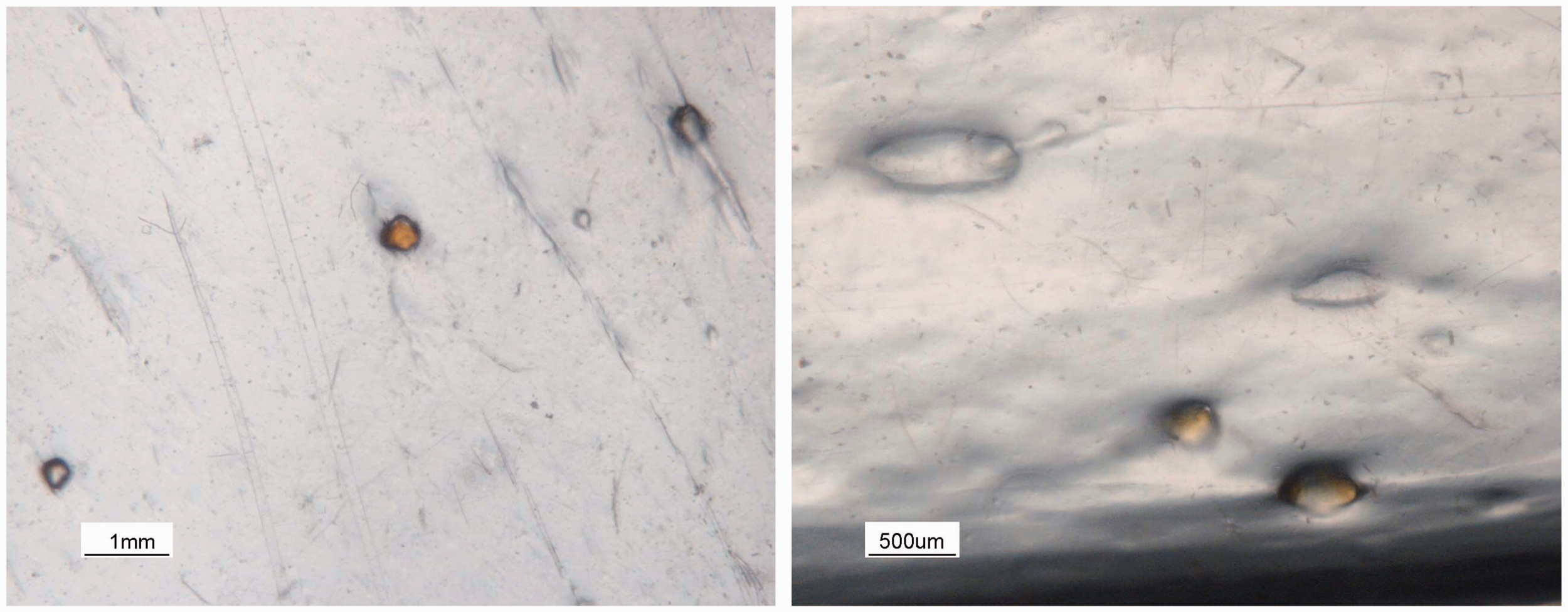
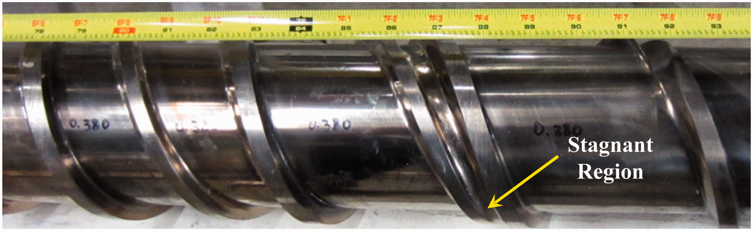
A hypothesis that the extruder was operating partially full due to the low specific rate during operation was proposed. To determine if partially filled channels caused the reduced rate, high discharge temperature, and degraded material, screw rotation was stopped and the hot screw was removed from the extruder. Examining the polymer on the screw indicated that in the meter section about half of the channel width on the trailing sides of the flights for all but the last diameter were filled with a dark-colored, partially carbonized LDPE resin, indicating that these regions were stagnant. The reduced flow rate caused these regions to be partially filled, creating void regions on the trailing side of the channel. Some resin adhered to the trailing side of the channel in the void regions and stayed there for extended time periods, as shown in Figure 12. The resin adhering in the void regions eventually degraded into the dark-colored, crosslinked material. Small process variations dislodged some of this material and caused the intermittent gel showers that contaminated the product. Moreover, compacted solids were found wedged in the channel at the entrance to the barrier section. The poorly designed barrier melting section entrance caused the relatively large entering solid bed to be forced into the continually decreasing barrier section solids channel width.
Photograph of a removed screw showing the resin flow and degraded resin due to stagnant regions.
9
A simple modification to the barrier melting section entrance solved this problem. For this modification, 8 some metal in the melt conveying channel was removed along with a portion of the barrier flight, allowing some solid material to enter the melt channel and reducing the restriction at the entry. By reducing the restriction, the process rate limiting step changed from the barrier section entry region to the metering section. This modification eliminated the gels.
Unmixed gels
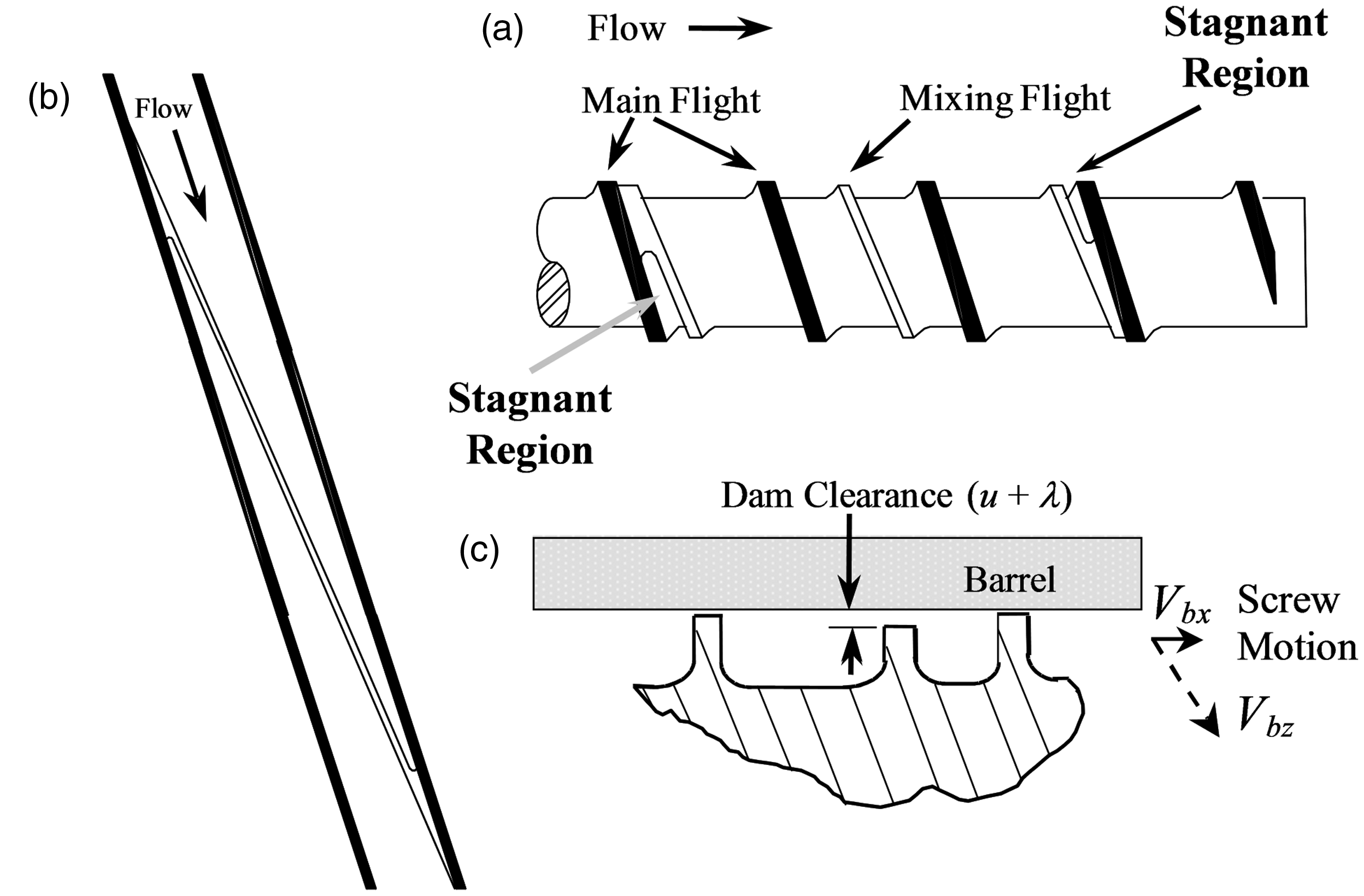
As stated previously, unmixed gels are highly entangled polymer chains that are molten when they exit the die. They solidify first upon cooling to produce a gel that appears as a solid polymer fragment. These gels are easily removed from an extrusion process by subjecting all molten resin to a one-time high stress near the discharge of the extrusion screw. This stress is easily applied using a Maddock-style mixer with a relatively tight clearance on the mixing flight.
The best way to disentangle unmixed gels and trap and disperse solid polymer fragments is with a well-designed Maddock-style mixer.10–13 Figure 13 shows a schematic of a Maddock-style mixer. The mixer is designed with pairs of in-flow flutes and out-flow flutes and a mixing flight with a narrow restriction. The resin flows into the in-flow flute. Next, the flow passes through the narrow restriction created by the mixing flight and the barrel wall. This narrow restriction will disentangle unmixed gels and trap, melt, and disperse solid polymer fragments from the barrier melting section. The resin then flows to the out-flow flute and to the downstream screw sections.
A schematic of a Maddock-style mixer. (a) axial mixer and (b) mixer cross section.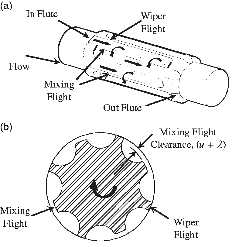
The preferred Maddock mixer design is a typical design plus two features.12,13 These design features include setting the mixing flight undercut to about 0.5% of the diameter. Most designs set this undercut at 1 to 1.5% of the diameter. The small undercut specified here will disentangle unmixed gels 1 and trap and disperse all solid polymer fragments that happen to exit the barrier melting section. A larger 1 to 1.5% undercut can allow unmixed gels and solid polymer fragments to discharge from the extruder. When made into films, these unmixed gels solidify first and produce a gel that looks like a solid polymer fragment.
The second different feature recommended here is that the in-flow and out-flow flute depths should be half the flute width. 12 If the flutes are made deeper, resin degradation can occur, creating gels in the film product. Maddock mixers with extremely deep flutes and large clearances on the mixing flights are common on smooth-bore extruder designs.
A film process was producing a monolayer film that had a low gel level. The gels were tested using hot-stage microscopy and identified as highly entangled species (unmixed gels). These gels melted and then disappeared when heated and stressed via pressure smearing using a dental tool (Figure 14).
Photographs of an unmixed gel at select temperatures using a hot-stage microscope.
1
The un-mixed gel melted at about 135℃. When the gel was smeared by moving the glass cover slip, the stress was enough to disentangle the polymer chains such that the gel would not reappear upon cooling.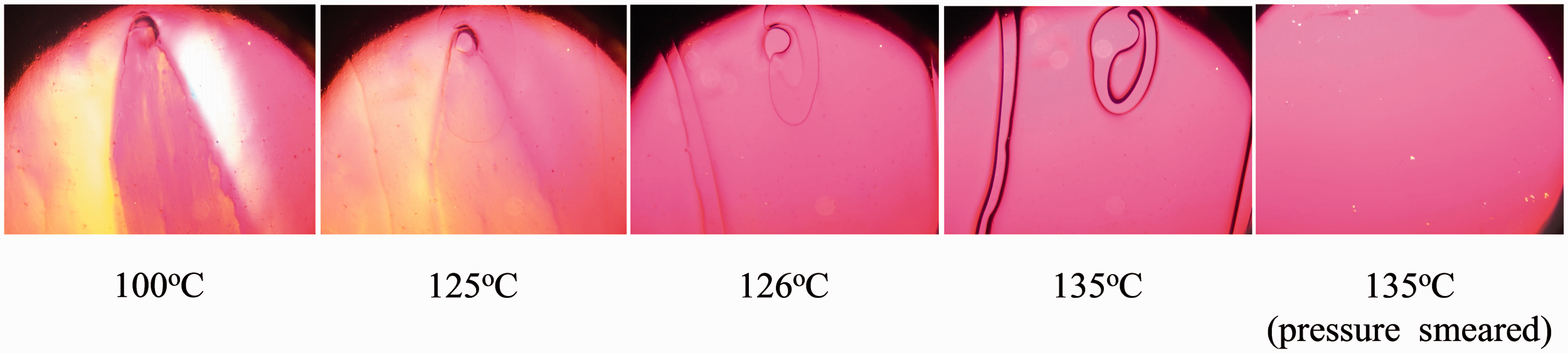
Increasing the stress level in the Maddock mixer eliminated the unmixed gels from the extrudate. Decreasing the mixing flight clearance increased the stress. The stress level required to disperse unmixed gels depends on the resin and the chain entanglement. Experience says that the stress level required to disperse PE unmixed gels is about 100 to 200 kPa.
A similar problem with solid polymer fragments occurred for a thermoplastic polyurethane (TPU) resin. 14 For this case, a lower compression ratio, a longer barrier section with a very small barrier flight clearance, a Maddock mixer with a small mixing flight clearance, and deeper metering channels allowed the TPU resins to extrude at twice the rate and provide high-quality extrudates that were free of solid polymer fragments.

Carbon specks in a film product
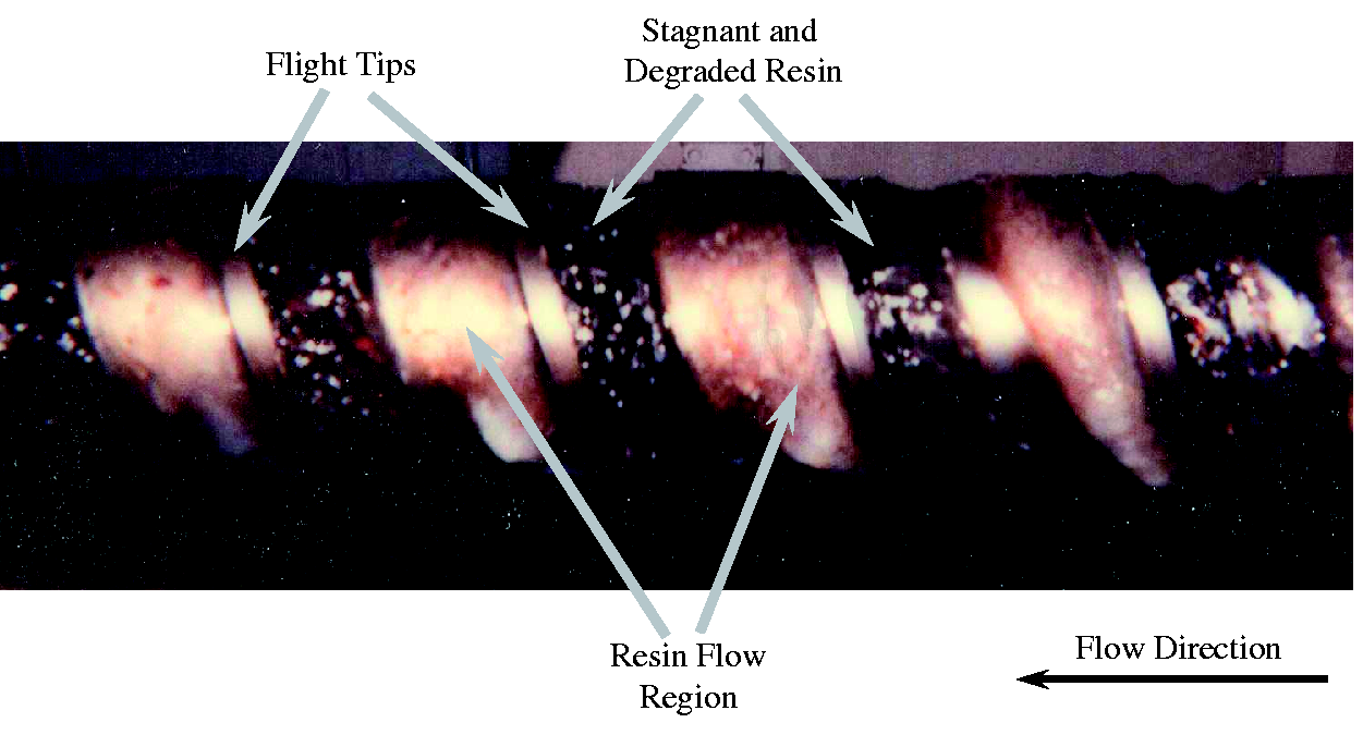
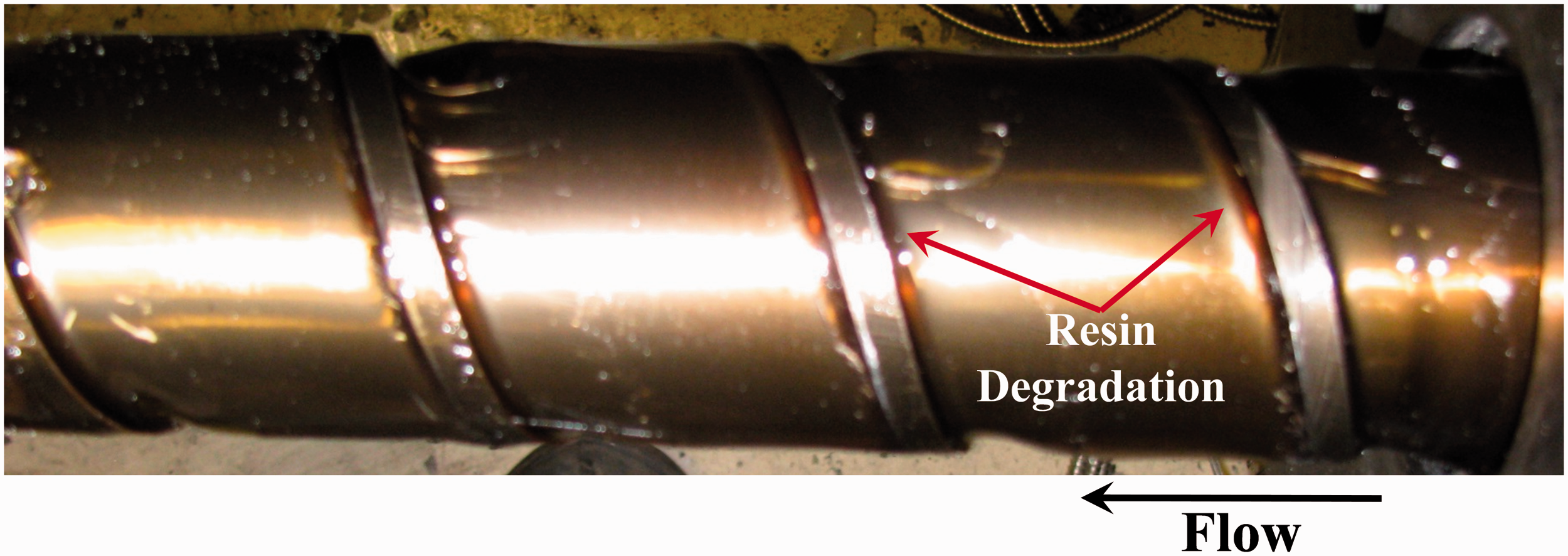
Stagnant regions in the extruder channels and in downstream transfer lines and dies can generate carbon specks. In general, these regions are not very large like those in Figure 12. Instead, they are thin coverings that occur at the flight radii or at entry and exits of mixing devices. 1 In general, the region will first create small crosslinked materials that adhere to metal surfaces. With additional residence time, the crosslinked material will form a thin highly oxidized carbon layer. When the layer breaks away from the metal, it becomes black specks in the PE film. These specks will fluoresce under UV light.
An LLDPE blown film line was experiencing black specks in the product. To locate the source, a Maddock solidification experiment
15
was performed where a small amount of a red color concentrate was added to the feedstock resin, after the red color appeared in the extrudate screw rotation was stopped, and the resin was solidified in the channels. Figure 15 is a photograph of the experimental sample.
16
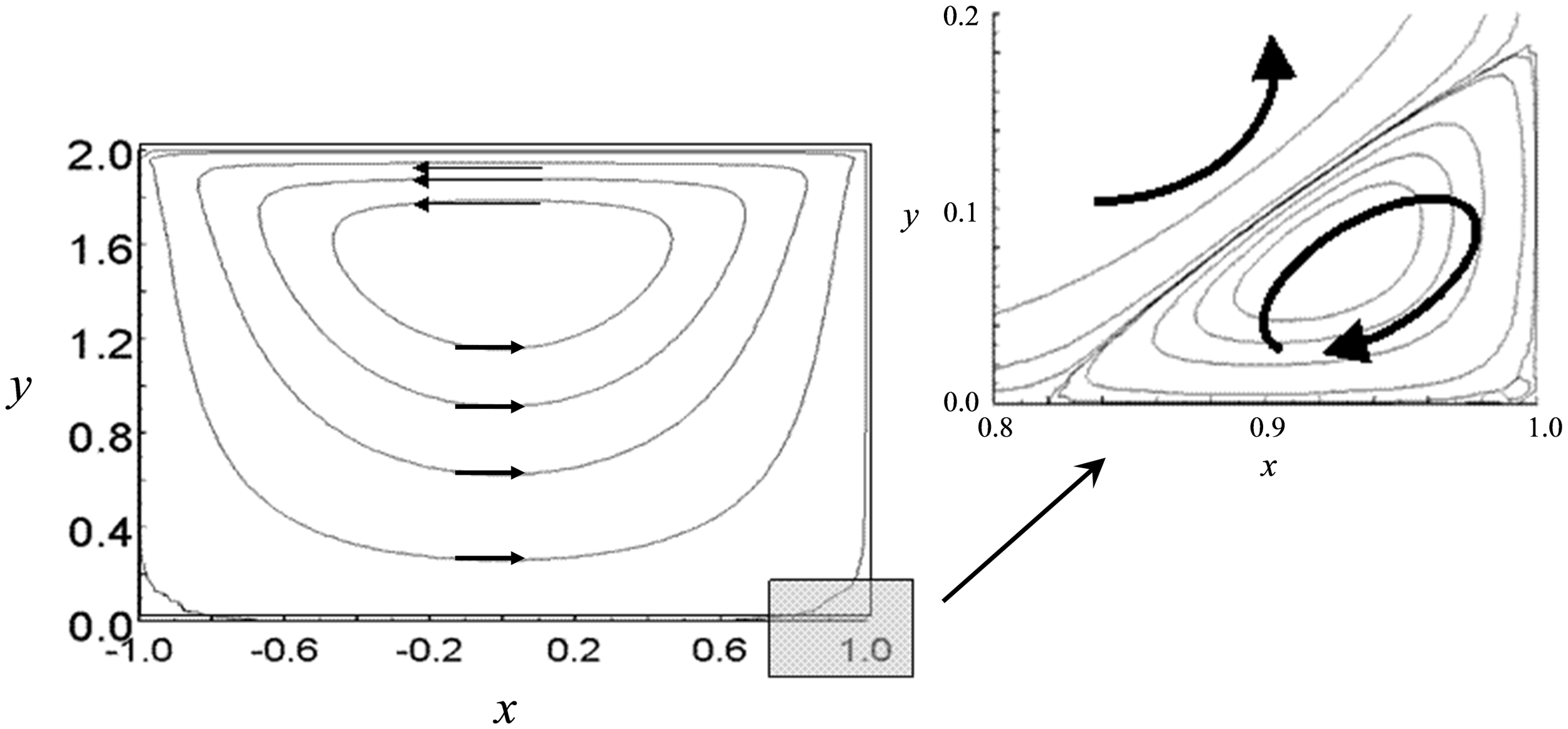
Here thin carbonaceous material formed at the pushing flight due to Moffat eddies.
17
Moffat eddies are recirculations or vortices that occur at sharp corners (Figure 16). That is, when fluid is put in motion with top driven cavity flow, flow circulation is generated in the channel (Figure 16). A secondary circulation also develops in the channel stationary corner, creating a low-velocity helical eddy that is outside the high-velocity flows in the main channel. The interface between the main flow and the eddy flow is complicated due to self-adhesion
18
and is beyond the scope of this work. Figure 17 shows another degradation example caused by Moffat eddies for an LLDPE resin. For this case, the degradation separated from the screw and caused a low-level gel contamination in the film product.
Photograph of degradation at the pushing flight for a screw running linear low-density polyethylene (LLDPE) resin
16
due to small flight radii and Moffat eddies. Two-dimensional flows in a screw channel with an H/W = 1 (channel depth / channel width). The arrows show the recirculation flows. The shaded area in the lower right corner is expanded to show the Moffat eddy.
1
Photograph of degradation at the pushing and trailing flights for a screw running linear low-density polyethylene (LLDPE) resin.
19
The Moffat eddies that created the degraded resin occurred because the flight radii were too small for the channel depth. If the flight radii would have been larger, the Moffat eddies would not have occurred and thus carbon deposits would not have formed.
The Society of the Plastics Industry, Inc. (SPI) guidelines state
20
“unless otherwise specified the root radius will not be less than 1/2 of the flight depth up to 25 mm radius.” Many screws are often designed, however, with flight radii that are very small and approach values that are between 10% and 20% of the channel depth. Previous research
16
has indicated that the SPI guideline as a minimum is appropriate for many resins. But for thermally sensitive resins, radii up to 2.5 times the depth are optimal. Flight radii sizes are shown in Figure 18. When a new screw with radii equal to the depth of the channel was built and installed into the blown film line, the black specks were essentially eliminated. Flight radii that are 1.5 times larger than the local channel depth for channels that are completely filled with resin are recommended for PE resins.
Schematic of small (R
1
) and large (R
2
) flight radii: (a) this small flight radii will likely create a Moffat eddy and lead to degrading the polyethylene (PE) resin, and (b) this large radii will likely not create a Moffat eddy.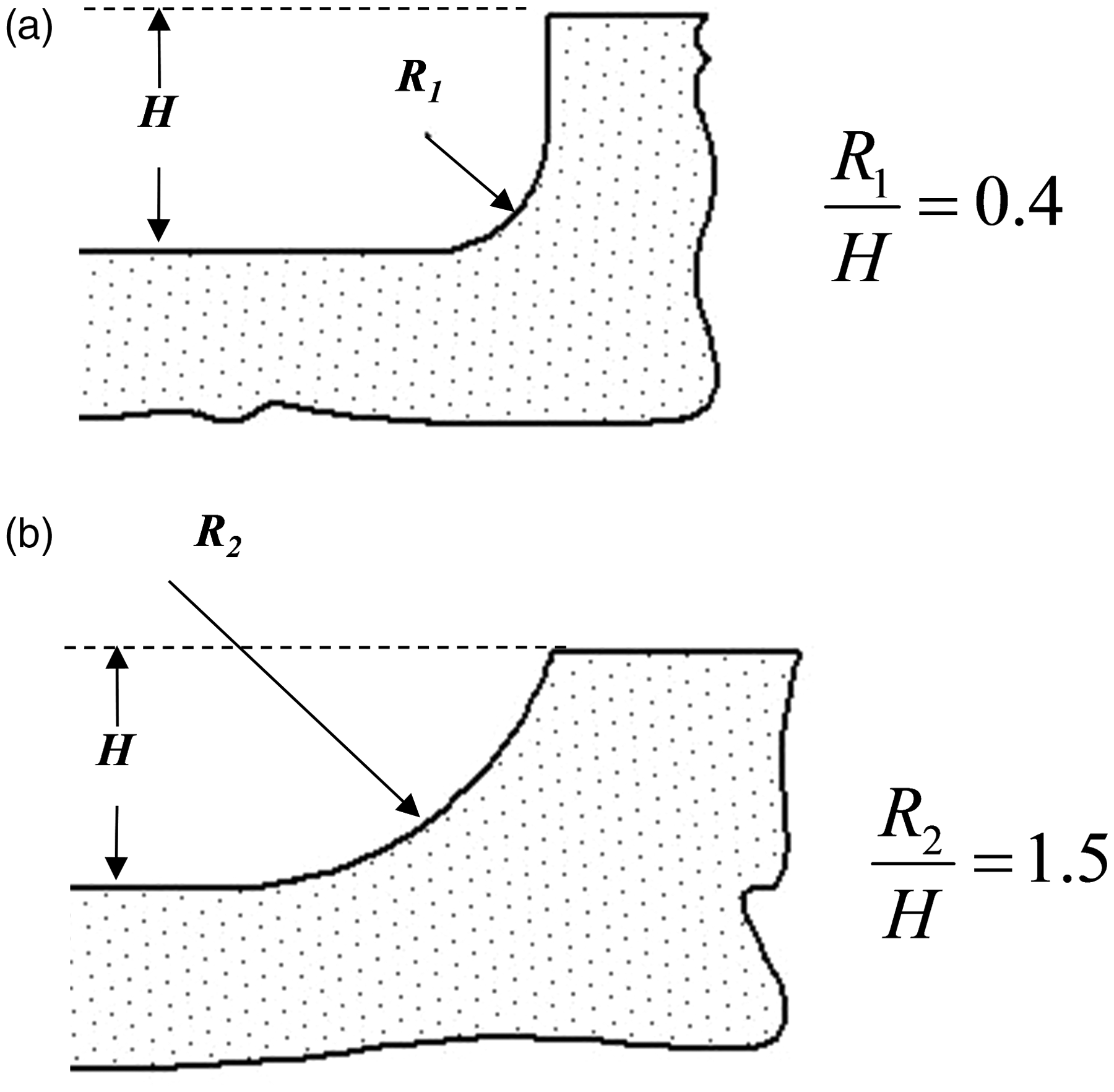
Filler agglomerates
Some specialty films use masterbatches with high mineral filler levels. The filler materials must be compounded using a properly designed process such that fillers are not agglomerated prior to dispersion into the base resin. If the filler is not completely dispersed when compounding a masterbatch, the agglomerates are essentially impossible to disperse during the film production process and lead to optical defects. For example, a compounding operation for making a specialty resin from a high-impact polystyrene (HIPS) resin and specialty filler chemical was not designed properly. Here the filler chemical was partially agglomerated prior to the melting process in a twin-screw extruder. Figure 19 shows the black-colored resin and the white filler chemical. These white agglomerates could not be eliminated in the final plasticating process (injection molding in this case) and created defects in the product. The goal for this application is to produce masterbatches that are filler agglomerate-free since the final film-making extrusion process is not able to disperse them.
Photographs of specialty high-impact polystyrene (HIPS) resin pellets made using a poorly designed process.
1
The white specks are filler agglomerates: (a) × 1 magnification and (b) × 4 magnification.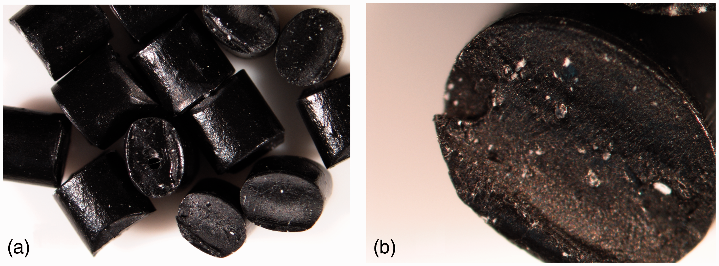
Discussion
Gel defects are common in PE film products, and they can originate from many different sources, causing lower product quality and sometimes stopping production. Gel types, identification protocols, and mitigation strategies are presented in this paper. Mitigating or eliminating gels quickly via the best technical solution will reduce costs to the plant and maximize profits.
The equipment and techniques required to diagnose properly the many different gels can be expensive and require highly trained people. Many small converters will not be able to afford these capabilities. Most resin suppliers, however, have the capabilities and are willing to aid customers on gel identification and mitigation.
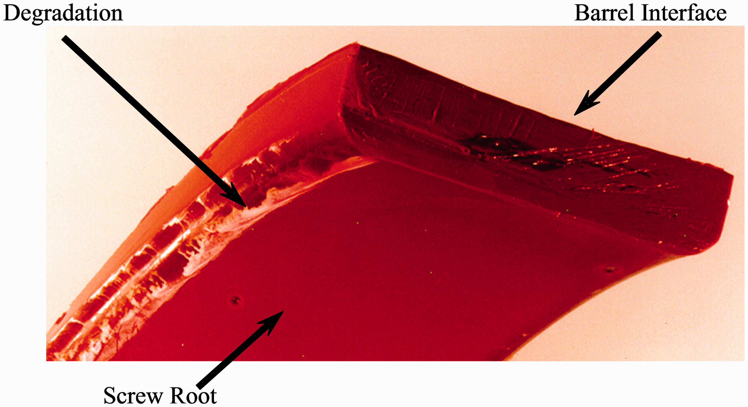
There are several locations on screws where stagnation and resin degradation are prone to occur. Common areas include poorly designed barrier section entries and exits, at the flight radii in channels where the resin is molten, and in poorly designed mixers or mixers that are not suitable for PE resins. Degradation is common for barrier section designs that use an advancing lead barrier flight. For this design, the barrier flight starts at the pushing side of the channel and ends downstream at the trailing side. This design is commonly referred to as a Maillefer design.
21
The original patent was issued in 1962 and since then many modifications have been made to mitigate stagnation locations. The design, however, is still used even though the defect is known to occur. Figure 20 shows the entry region where stagnation can occur. The photograph shows the very deep and very narrow melt conveying zone at the entry, which causes flows to be very low and stagnant deep at the root. Barrier melting sections where the barrier flight is parallel to the main flight are recommended.
Photograph of a stagnant region at the entry area of a Maillefer barrier melting section.
19
Many different mixer designs are often added to extruder screws used to plasticate PE resins for blown film, cast film, sheet, and pipe. Several mixer designs are not recommended for use with PE resins due to stagnant regions that occur in the mixer. The most common mixers used commercially that should not be used with PE resins include cavity transfer mixers, cross-flow plate mixers, and spiral dam mixers. Figures 21 and 22 show these devices, and they all have regions where the resin can stagnate and cause the resin to degrade. These devices are very commonly designed into screws used with groove-bore feed sections.
Photographs of mixers commonly used with grooved-bore extruder screws, showing locations for resin degradation and stagnant regions: (a) a CTM, (b) cross-flow plate mixer with resin degradation, and (c) side view of a cross-flow plate mixer. These mixers are not recommended for polyethylene (PE) resin extrusion. Schematic of a spiral dam. This mixer is not recommended for polyethylene (PE) resin extrusion. (a) Spiral Dam, (b) Unwrapped view and (c) Cross section view.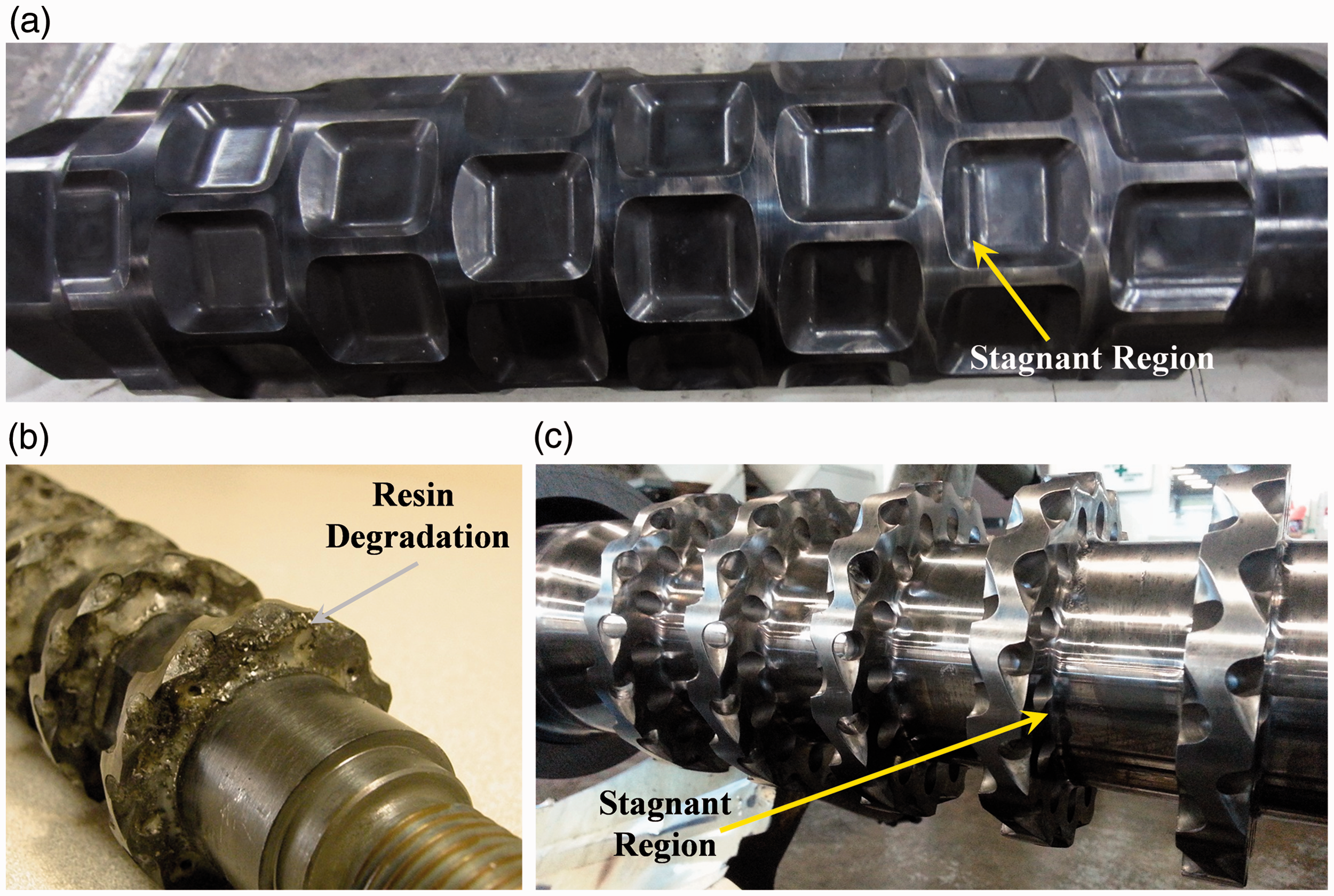
The CTM22,23 is constructed by positioning concave cavities on the screw shaft and into the barrel wall. Different cavity shapes are practiced commercially. Mixing occurs by forcing material into and out of the cavities. The cross-flow plate mixer is constructed by positioning circular plates on the shaft of the screw and cutting holes through the plates that flow resin from near the barrel wall to the root of the screw and also from the root to the barrel wall. The land of the plate is in close proximity to the barrel wall.
The CTM performs well for melting and dispersing solid polymer fragments. This mixer, however, can increase the extrudate temperature to unacceptable high levels 24 and cause resin degradation deep in the cavities. Because of resin degradation, CTMs are not recommended for extruding PE resins.
The cross-flow plate mixer has numerous sharp corners where the circular plates attach to the screw root. These corners create stagnant regions and allow extremely long residence times, causing degradation. Figure 21(b) shows obvious resin degradation. Moreover, a large portion of the barrel wall in the section is not wiped by the screw, reducing the local heat transfer and allowing some material to have extended residence times. Cross-flow plate mixers are not recommended for extruding PE resins.
Other mixers often used with grooved-bore extruder screws are spiral dams. Spiral dams are a dam (or secondary flight) that starts at the pushing side of the channel and ends downstream at the trailing side, (Figure 22). The small pockets at the entry and exit are typically stagnant and regions where resin can degrade. The design flaw here is essentially identical to that of a Maillefer barrier section. Dispersive mixing occurs as the resin flows across the narrow dam clearance. Spiral dams are not recommended for PE extrusion.
Although this work is based on PE resins, the concepts and stagnation locations can also cause degradation processes to occur for many other resins including polystyrene (PS), polycarbonate (PS), and acrylonitrile butadiene styrene terpolymer (ABS).25,26 Eliminating locations on the screw where resin can be stagnant is a good practice for all resins.
Footnotes
Summary
This paper describes the different gels that are likely to occur in PE film products, techniques for identifying the gel type, and technical solutions to mitigate them from single-screw extrusion processes. Devices and regions that are known to create stagnant regions and thus create resin degradation are identified.
Declaration of Conflicting Interests
The author(s) declared no potential conflicts of interest with respect to the research, authorship, and/or publication of this article.
Funding
The author(s) received no financial support for the research, authorship, and/or publication of this article.