
Abstract
Controlling the energy consumption in PM processes is becoming increasingly crucial, as in all competing industries. It has been shown that the core PM process of sintering is responsible for most of the energy consumption. 1 2 To improve understanding of the energy flows, a detailed analysis has been undertaken of a typical belt furnace, involving the mass flow of belt, sinter trays and payload as well as the flow of protective gases, combustible gases and electric energy. Different loading conditions were investigated to generate a complete image of the furnace. Various details have been analysed in a flow canal to understand the physics. The monitored data were matched and checked against a calculated physical balance.
Legislative requirements and rising energy prices are placing increasing pressures on all manufacturing sectors, including PM. However, beyond the interest of designing and operating efficient processes with low energy consumption, the quality of the sintered products is essential. Every PM producer knows of situations where the overall hardness, the surface hardness or dimensions of the sintered parts have not been adequate. All these observations provide the motivation for the series of investigations briefly presented in this paper.
Experiments with sinter furnace
The sintering furnace used for the experimental investigations and the basis for the calculations was a Mahler belt furnace that is representative of the state of the art (Fig. 1). The furnace was equipped with a delubrication zone directly heated by gas burners, an electrically heated sintering zone, a rapid cooling zone and balancing ventilators in the cooling zone (Fig. 2). The balancing ventilators are responsible for the axial stability of the atmosphere along the furnace. For some experiments the rapid cooling and balancing ventilators were shut off to represent a conventional furnace without rapid cooling. The atmosphere was a nitrogen–hydrogen gas mixture.
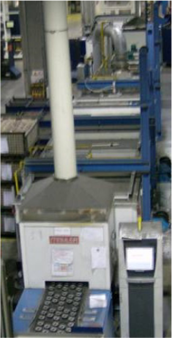
The Mahler furnace investigated
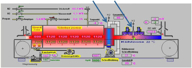
Schematic layout of investigated Mahler furnace (screenshot of furnace control panel): the rapid cooling and the balancing ventilators were shut off for some experiments
The energy input from combustible gases and electric energy was well metered. The actual loading conditions such as the mass flow of the belt, sinter trays and payload are simply correlated to the total energy input: the measurements here showed a good correspondence with the calculated heat consumption (specific heat × mass flow × temperature difference).
The efficiency of the sintering process was defined as total energy input divided by the theoretical heat needed to heat the parts (payload) to the sintering temperature. The heat losses through the walls vary very little with varying pay load. The gas heat losses (exhaust fumes) are dependent on the payload. Thus, heavily loaded furnaces (600 mm belt, >400 kg h−1 of parts) reach efficiencies of ∼40%, whereas a rough average for most of the European GKN plants is 15–20%. Efficiencies are much lower for delicate small parts with a low furnace load. In view of the focus on energy consumption it should be helpful to gain a better understanding of the internal processes of the typical furnaces.
Energy flow in furnace
The original proposal was an investigation using infrared imaging (Fig. 3). This approach does help to locate weak spots of the design, but was eventually found not to be usable to meter the energy balance.
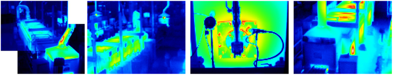
Infra-red images show ‘hot spots’ but were not feasible for evaluation of energy balance
The first step towards gaining an understanding of the physics was a theoretical model of the investigated furnace for a pinch analysis, which balances the energy flows at different temperatures, taking into account every known detail (Figs. 4 and 5). For example, (rapid) cooling demands a high mass flow of cold water to allow adequate cooling rates. Here the water removes the energy at a very low and thus thermodynamically useless temperature. It thus becomes obvious that most of the energy is lost at temperature levels that are not suitable for heat recovery (excepting the exhaust fumes at the furnace entrance, which are not re-usable within the process).
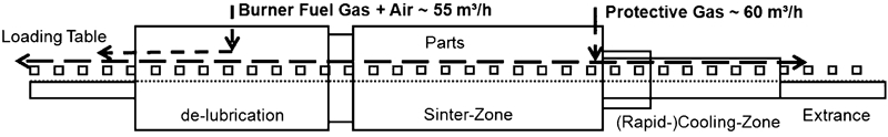
Principle of furnace used for investigation
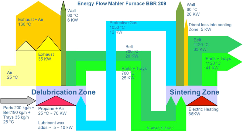
Example of a pinch analysis
Another example of the energy flow is the protective gas which, after travelling through the sintering zone, flows into the delubrication zone and thus helps to heat the payload.
The energy flow between the furnace zones is driven by the simple mass transport of the belt and payload. Nevertheless, energy mismatches were found that differed under different loading conditions.
Furnace walls
It seemed to be possible to describe the losses of the furnace walls well simply on the basis of physical heat conduction. Therefore the heat transfer from a furnace wall to the environment as a function of temperature difference was measured with a model set-up. Further, the furnace wall was punched at specific positions and thermocouples were introduced within and on the furnace walls (Fig. 6).
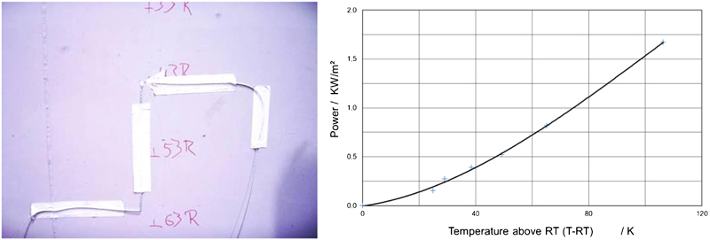
Furnace wall with thermocouples and energy loss from furnace surface measured with test rig
The energy loss through the walls did not fit the models, since at lower temperatures the loss was significantly higher than expected. This leads to relatively high heat losses when idling at lower temperatures (Fig. 7).
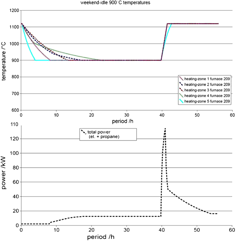
Electric energy consumption of furnace at lowered temperature and recovery: energy flow at recovery is noteworthy
A recalculation of the heat transfer showed that gaps between the bricks might have been responsible. First the total gap width along the length of the sinter zone was estimated with the hull maintained at a near constant temperature and the bricks changing their length in accordance with the temperature changes in the furnace. A convection calculation was then performed for different gap numbers. It was possible to confirm this theoretical result during a subsequent upgrading of the furnace since the calculation fitted almost perfectly the real number of gaps observed.
Atmosphere flow
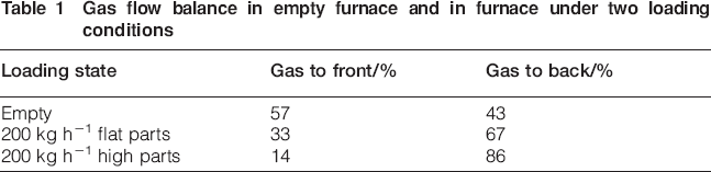
A further investigation focused on the atmosphere flow. Prandtl probes (Fig. 8) with a very sensitive pressure gauge were used to detect the flow with typical gas speeds of 0·1 m s−1. Interestingly the flow differed over a wide range from ∼60% of the atmosphere (at the inlet at the end of the sinter zone) flowing to the front section with an empty furnace to less than 20% at full load (Table 1).
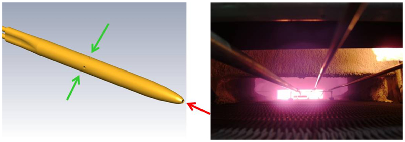
Prandtl probe and various probes in furnace
The cold atmosphere injected at the end of the sintering zone is heated by contact with the warm surfaces. This generates convection, which is superposed over the axial flow and results in a flow pattern consisting of two helices (Fig. 9). This effects intensive stirring of the gas.
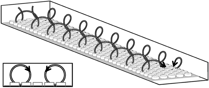
Principle of gas flow pattern in two helices through sinter zone
Atmosphere temperature
Thermocouple measurements of the gas temperature shielded against thermal radiation showed surprising effects. The temperature of the protective atmosphere, for example, did not reach the sintering temperature (Fig. 10). While the furnace was set to 1120°C (validated by a measurement from a thermocouple in a 300 g part) the gas temperatures were significantly lower. Depending on the payload, the gas reached temperatures that could be as low as a maximum of 1050°C before flowing into the delubrication zone – a further mismatch in the first pinch analysis. The Stefan–Boltzmann effect means that radiative heat transfer, which increases with the fourth power of the absolute temperature, is dominant; thus the sintered parts reach the sintering temperature owing to radiative heating and the gas convection is negligible.
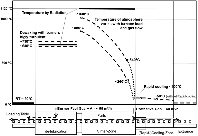
Measured gas temperatures differ greatly from radiation temperatures and vary widely
Flow canal and calculation of flow balance
To understand these measurements better, a flow canal (wind tunnel) was built to evaluate the drag coefficients of the various furnace elements. These data were used to determine the balance of the gas flow: the calculations took into account the local temperatures, densities, drag coefficients and gas speeds to balance the flow of the gas from the inlet to the entrance and to the end of the furnace. It also took into account the varying gas flow from the burners and thus balanced the whole system. The flow balances for an empty furnace and a loaded furnace are compared in Table 1. An important implication of these results is the importance of the quality and maintenance of the curtains at the end of the furnace.
Gas flow balance in empty furnace and in furnace under two loading conditions
The flow canal was also used to investigate thermodynamically the flow between sinter and delubrication zones, to improve understanding of this transition (Fig. 11). Owing to their higher density the relatively cold exhaust fumes containing some oxygen penetrate the sinter zone, while the hotter protective gas flows out of the sinter zone over the top of the exhaust fumes (Fig. 12). This may cause surface decarburisation which can be compensated for at the end of sintering in an endogas furnace but may in a mixed gas furnace (where the calculated gas flow to the front was less than 10%!) reduce the surface hardness (Fig. 13).
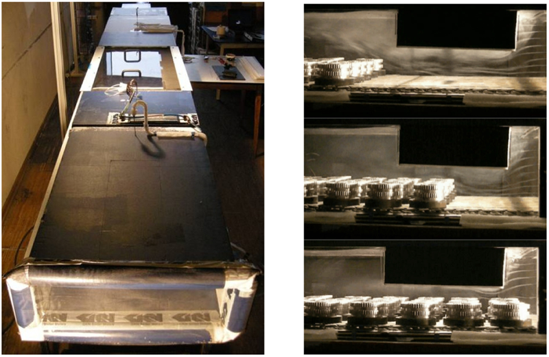
Left: flow channel. Right: fume threads in isothermal model show atmosphere flow passing parts as they move from delubrication into sinter zone
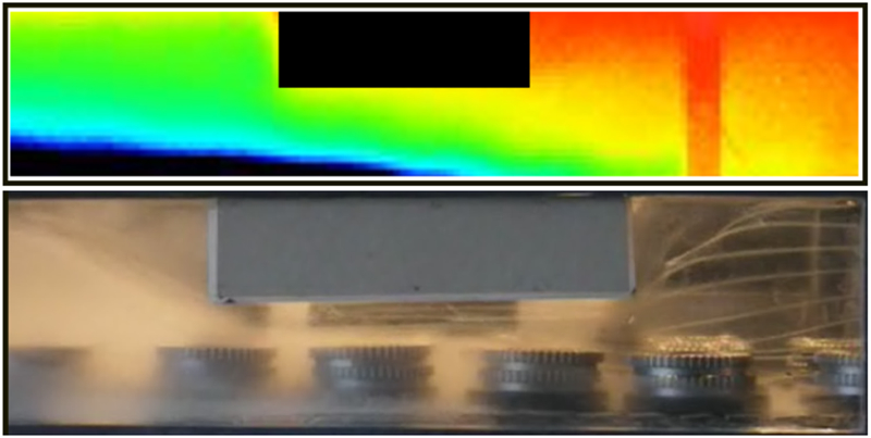
Fume threads showing flow of protective gas out of sinter zone (right) into delubrication zone (left) while a counter-flow of cooler exhaust fumes penetrates sinter zone. Top: infrared thermograph of flow canal screen; bottom: photograph showing fume threads visualising flow pattern
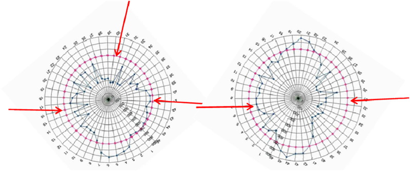
Hardness profiles at circumference of parts at start of production lot (dark blue spots/line), showing effect of decarburisation at flanks (both parts) and at lower and upper volume (left) if not protected by the lee of another part (right): arrowed (red) traces indicate specification; exhaust fumes in this graph came from ‘top’.
Conclusion
Energy flows and gas flows of a typical belt furnace have been investigated with surprising results. The investigations improved the understanding of the energy balance within a sinter furnace as well as various factors affecting the sintering quality. The task is now to develop this understanding further to improve the energy consumption as well as in the sintering quality achieved by these furnaces.
Footnotes
Acknowledgements
For their effort invested into these investigations I thank besides numerous colleagues especially Karen Murphy, René Albert, Thomas Schupp and Karl-Heinz Klug. This paper is based on a contribution to the Euro PM 2012 Congress organised by EPMA in Basel, Switzerland on 16–19 September 2012.