
Abstract
Powder metallurgy is a manufacturing technology widely used, especially in the automotive sector. In order to assure the quality of these components different conventional tests are employed directly on the final product, but in order to mechanically characterise the sintered material, standard mechanical tests can only be performed onto samples compacted and sintered in controlled conditions similar to the ones used in the real production. The final mechanical properties of these products after compacting and sintering are the input needed to define and analyze new geometries and products. The use of the small punch test (SPT) to mechanically characterise in a direct way the final sintered products was explained in this research work and the regressions to determine the tensile mechanical properties of the aforementioned products were also developed.
Keywords
Introduction
The small punch test (SPT) is a very useful test in many occasions, for example when the mechanical part to be characterised is small and it is impossible to use a standard test, as the tension test. The SPT uses small-sized specimens (10x10 mm and 0.5 mm thick) which are firmly clamped between two circular dies and are bi-axially strained until failure into a circular hole using a hemispherical punch (Fig. 1). The ‘load-punch displacement’ record can be used to estimate the yield strength 1–6 the ultimate tensile strength 1,3-6 and the tensile elongation.
3
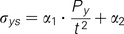
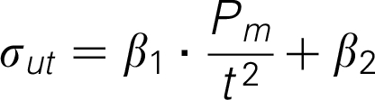
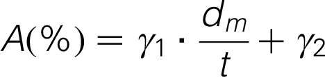
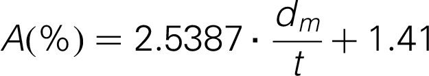
Figure 2 shows the typical plot of the load versus punch displacement of a ductile metallic alloy with different zones marked on it. In the limit of zone I and II, we can obtain the Py load, which divided by the square of the specimen initial thickness (t) gives us the material yield strength (σ
ys
), through a linear relationship. Moreover, it is possible to obtain the tensile strength (σ
ut
) and the tensile elongation (A) from the load (Pm) and displacement (dm) respectively obtained at the maximum load point of the graph. Typical relationships between these parameters are:1,3–6
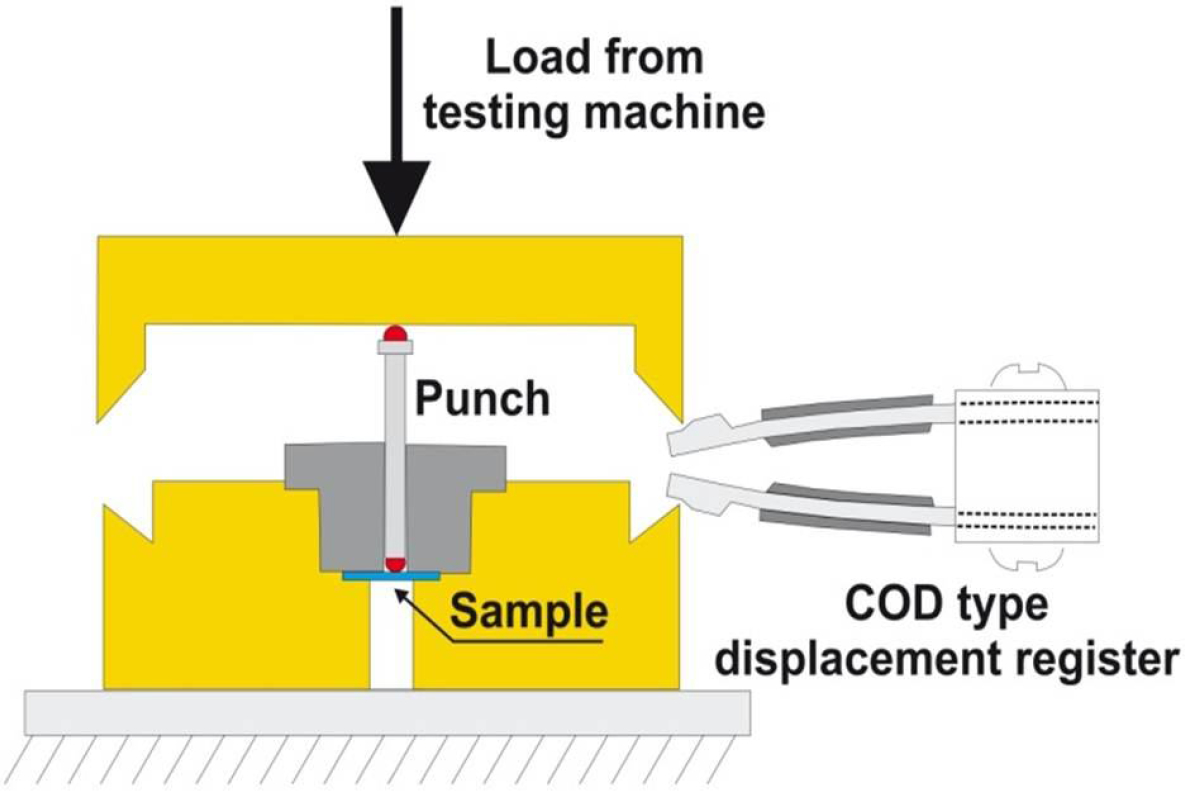
SPT test device
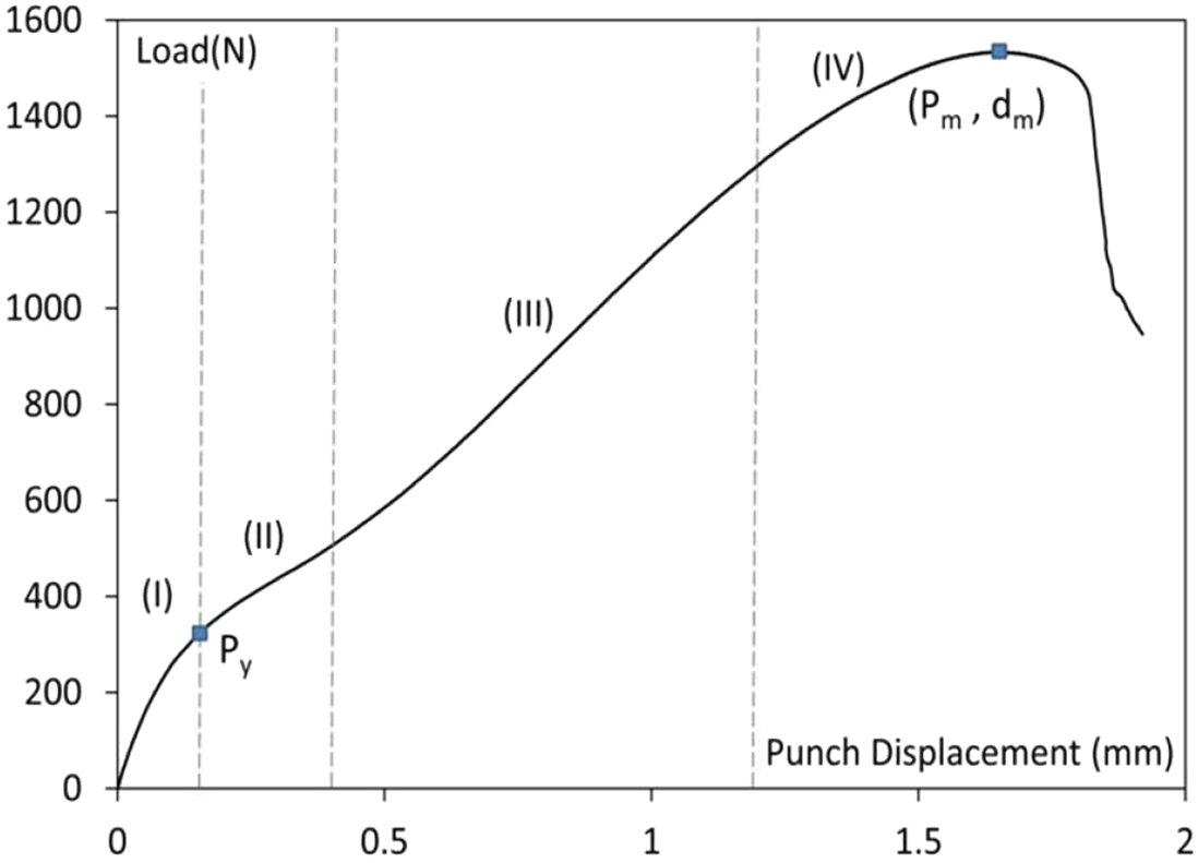
load-deflection SPT curve with identification of the different curve zones
The aim of this work was to evaluate the applicability of the SPT to estimate the mechanical properties of powder metallurgy products used in the automotive industry. To achieve this target, the characteristic curve of the SPT was analysed, extracting the characteristic values of load and displacement. Finally, these values were compared with parameters obtained from conventional tensile tests to ascertain whether there is any correlation between them. Finally, these relationships were used to estimate the mechanical properties of commercial synchroniser hubs used in vehicle gearboxes.
Materials and processing
Tests were carried out using three different commercial powders: Mat1, a diffusion-bonded powder of nominal composition Fe-0.5Mo-1.5Cu-4.0Ni (0.5% graphite and 0.8%wax); Mat2, a prealloyed /diffusion-alloyed powder of nominal composition (Fe–1.4Mo)–2.0Cu–4.0Ni blended with 0.6% graphite, 0.3% MnS and 0.8% wax; and Mat3, a prealloyed Fe–3Cr–0.5Mo powder blended with 0.3% MnS, 0.8% wax and 0.45 or 0.60% graphite. Two types of samples were cold pressed at 600 MPa from these blends: prismatic samples (PS, Fig. 3) and commercial synchroniser hubs (SH, Fig. 4).

Prismatic type sample (PS) and positions of the extracted test specimens
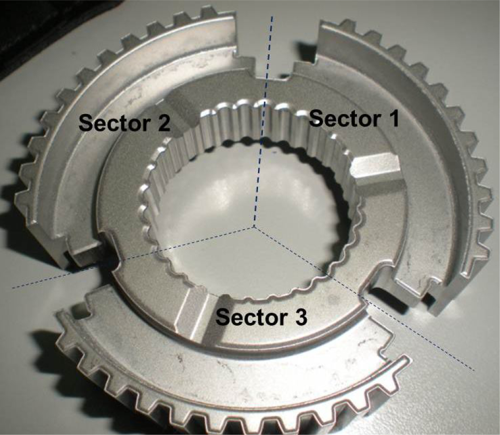
Commercial synchroniser hubs (SH)
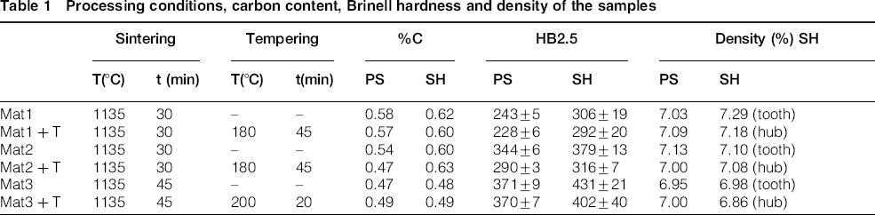
The samples corresponding to Mat1 and Mat2 were double-pressed and double-sintered: presintered at 800°C for 45 min in furnace under a N2/H2 atmosphere, repressed to a density around 7–7.1 g/cm3 and finally sintered for 30 min in a belt furnace at 1135°C under endogas. Mat3 samples were pressed to an average density of 6.95–6.98 g/cm3 and sintered for 45 min in a roller furnace at 1135°C under a 90N2–10H2 atmosphere. Finally, 50% of the prismatic samples and synchroniser hubs were tempered for 45 min at 180oC (20 min at 200°C in the case of Mat3 samples).
The total carbon content of the different samples, evaluated using standard Leco analysers, is summarised in Table 1.This table also shows the HB2.5 hardness of all the samples measured according to DIN 30910 (Part 4) and the density results, according to ISO 2738:2000. Note that hubs showed in all cases a higher hardness than PS samples. Differences in geometry and carbon content can explain these results. 7
Processing conditions, carbon content, Brinell hardness and density of the samples
Tensile and Small Punch test correlations
Tensile and SPT specimens were wire cut from the PS samples at the locations and orientations shown in Fig. 3. Tensile specimens 4mm wide, 0.5mm thick and with a gauge length of 25 mm were tested according to DIN-EN-10002-1 in a universal testing machine at a crosshead speed of 1 mm/min.
In order to avoid microstructural and porosity differences 8 as much as possible, small punch specimens were extracted at the same Z coordinate (Z was the press direction) as the tensile ones. Moreover, with the aim to analyze possible orientation effects, SPT specimens oriented in the other two directions (X and Y) were also used (Fig. 3). SPT specimens had a standard geometry (10x10x0.5mm) and were tested using the experimental device depicted in Fig. 1, mounted on a universal testing machine with a load cell of 5 kN. A punch diameter of 2.5 mm, a hole in the lower die with a diameter of 4 mm (provided by a 0.2 mm corner radius) and a displacement rate of 0.2 mm/min were used in all these tests.
Figures 5 and 6 show respectively the tension and SPT curves obtained with the specimens extracted at mid-thickness (Zm). The parallelism of the results obtained with both type of tests is highlighted.
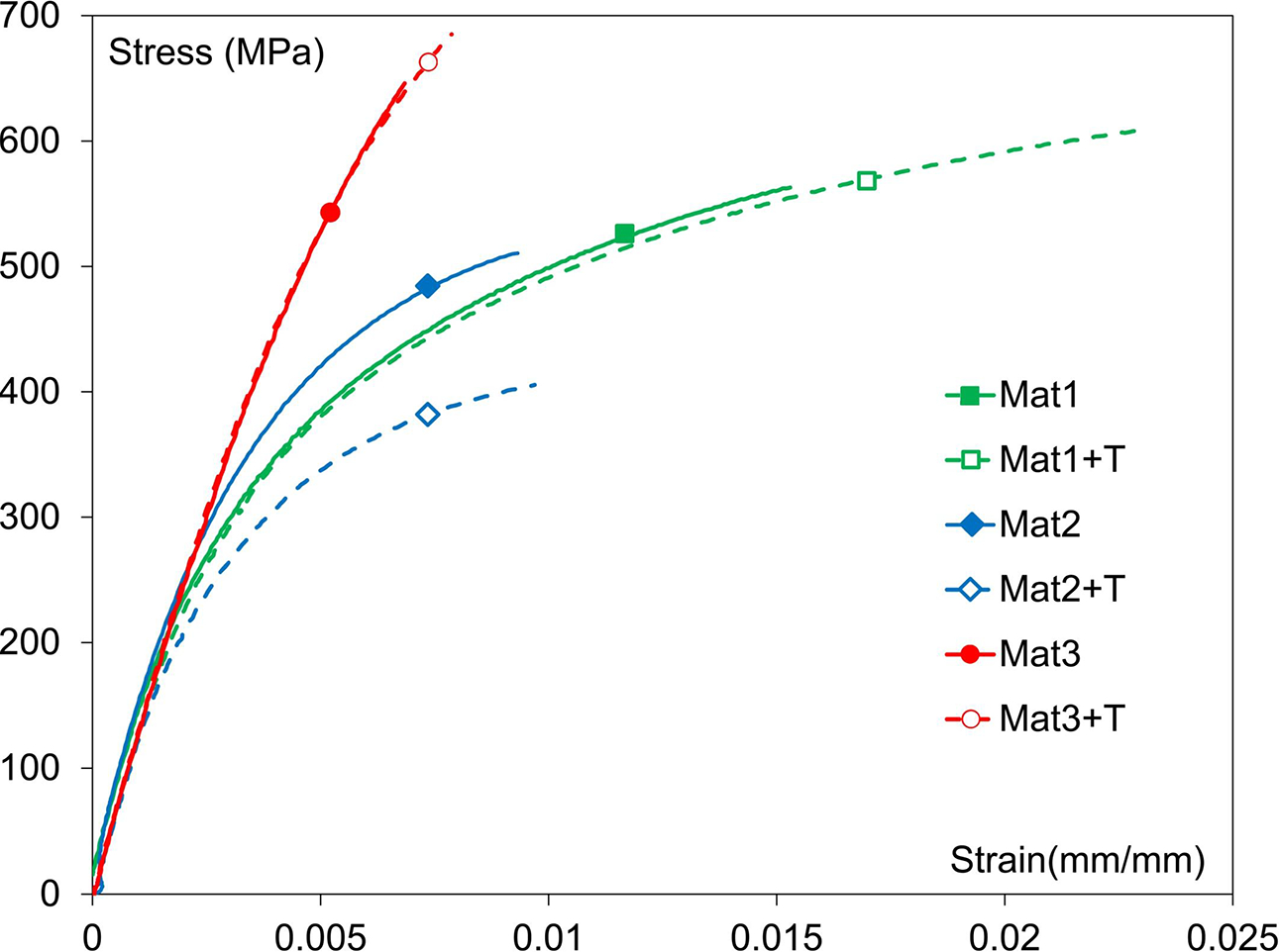
Tensile tests characteristic curves
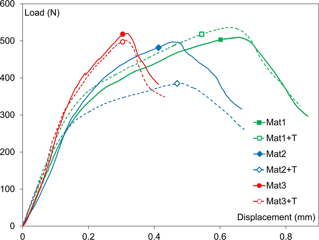
SPT characteristic curves
Table 2 summarises the average values and the standard deviation of both tensile and SPT parameters obtained with all materials and treatments at the different Z locations (near surface, Zs and mid-thickness, Zm). Values of SPT parameters corresponding of X and Y orientations have not been included because no significant difference was detected relative to Z orientation. Only in the case of Mat3 sintered and sintered and tempered the X and Y orientations parameters were slightly larger than the Z ones.
Tensile properties and SPT related parameters
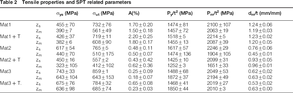
The influence of the specimen location along the Z axis (Zs versus Zm) is worth highlighting. The mid-thickness specimens generally show lower strength and ductility than the specimens located near the sample surface. These facts can be explained, first due to the larger cooling rate suffered by the sample surface (microstructure with a higher strength 8 ) and also because the porosity is usually larger in the center of the compacted and sintered samples 9 .
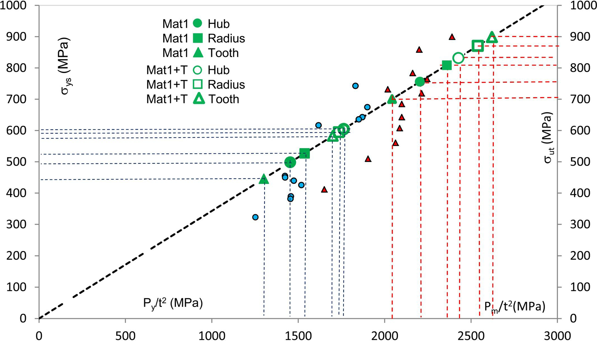
Figures 7, 8 and 9 show the correlations obtained between the tensile mechanical properties and the corresponding SPT parameters. The obtained regressions are quite good and, in the case of the yield and the ultimate strengths, the obtained expressions are very similar. Figure 10 shows the Py/t2-σys values obtained in this work together with those obtained by García et al.
10
for a wide range of metallic materials. This figure also shows the Pm/t2-σut values obtained in this work. We can appreciate that all points can be adjusted by a linear regression with the same slope:
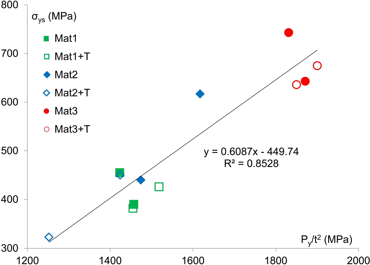
Py/t2 versus σys
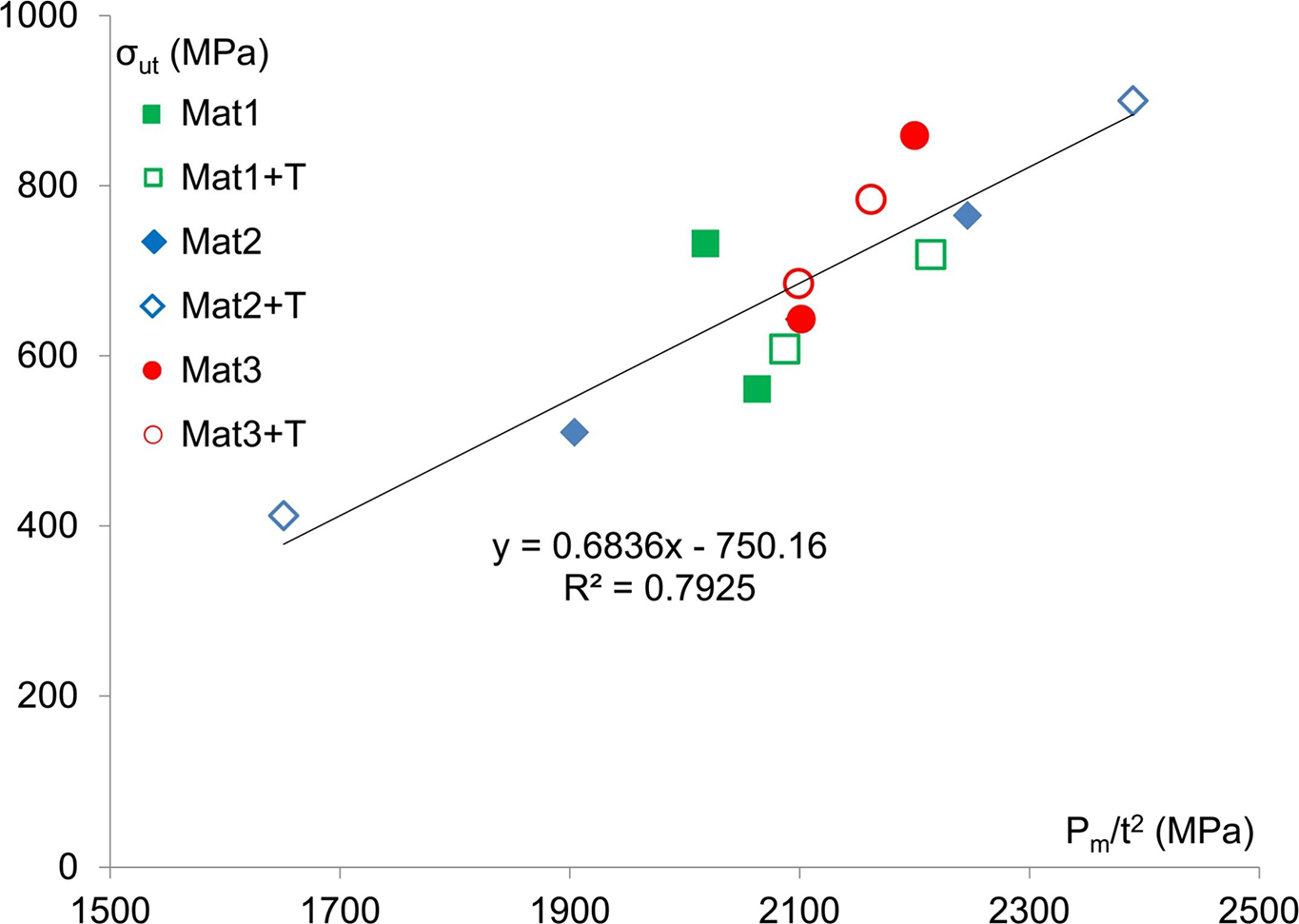
Pm/t2 versus σut
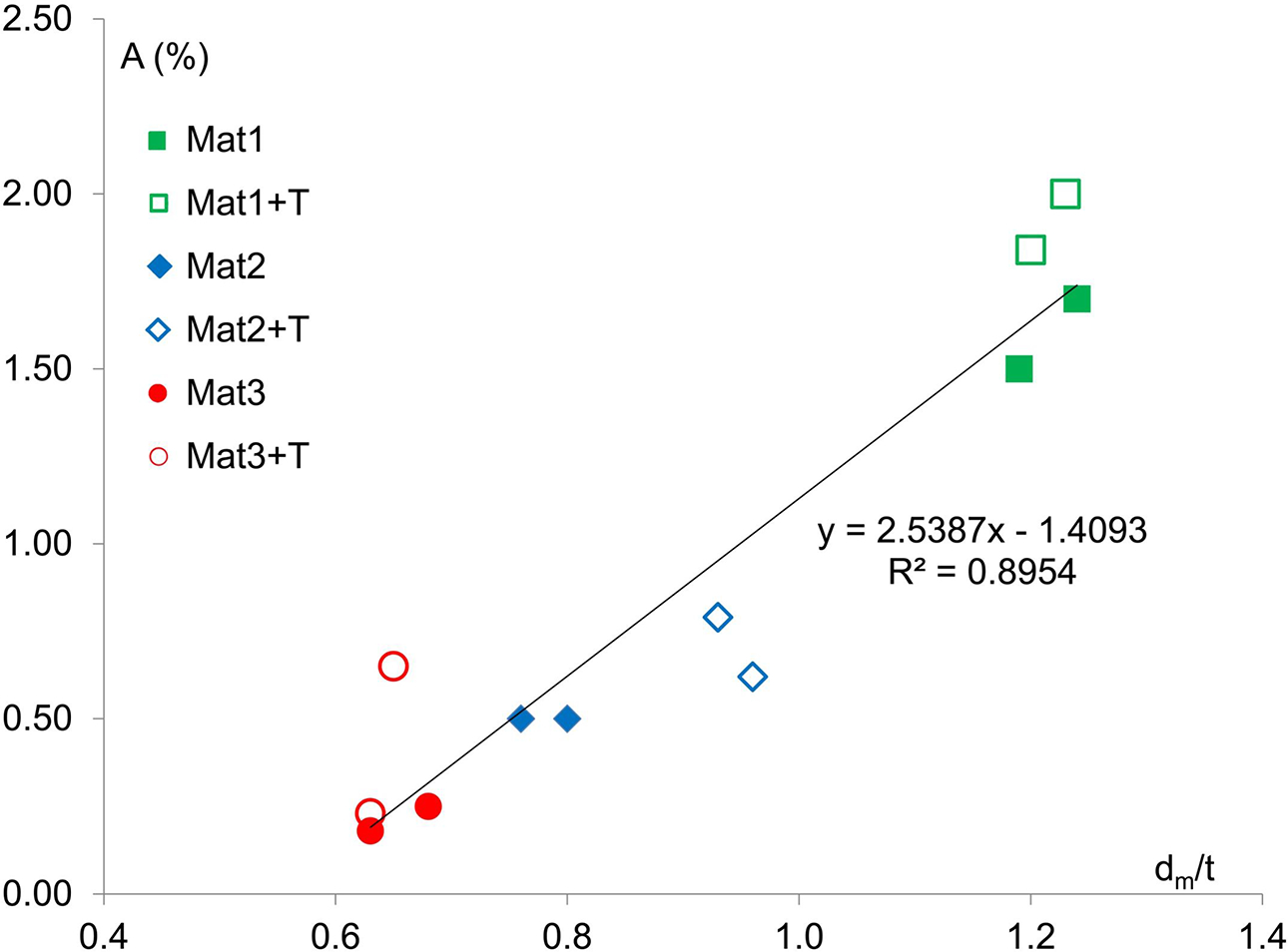
dm/t versus elongation
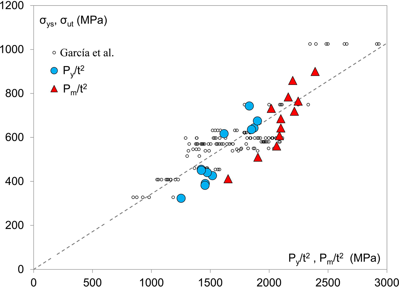
Py/t2 vs σys, Pm/t2 vs σut and correlation proposed by Garcia et al. 10
Application to the synchroniser hubs
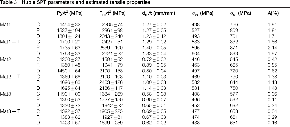
With the aim of evaluating the mechanical properties of the three characteristic zones of the hubs (hub: C; radius: R; tooth: D), SPT specimens were extracted from the three sectors of the hubs at the locations and orientations shown in Fig. 11 (this figure only shows a single sector of the component). Note that D and C samples were extracted with the thickness in radial direction while the thickness direction of the R samples was the pressing direction. Figure 12 shows, as an example, the SPT curves representative of different parts of the hubs proceeding of Mat1. The SPT parameters obtained with all the evaluated synchroniser hubs are shown in Table 3. In general, the hub zone showed lower resistance and ductility than the radius one. This fact can be explained due to the larger thickness of the hub portion relative to the radius region. Thus, the hub region will firstly cool more slowly (giving way to a less resistant microstructure) and, secondly, its density will be lower because the same pressing force is used in both zones. The behavior of the tooth region, however, is more variable, depending on the porosity of the specific area where the SPT specimen was extracted. Table 3 also shows the values of the tensile properties obtained from the SPT parameters using expression (4) for the yield stress, expression (5) for the ultimate strength and expression (6) for the elongation (Fig. 10):
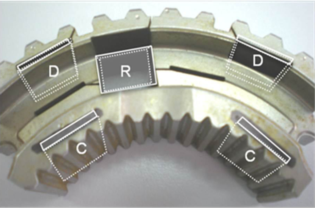
Location and orientation of the SPT specimens in the hubs
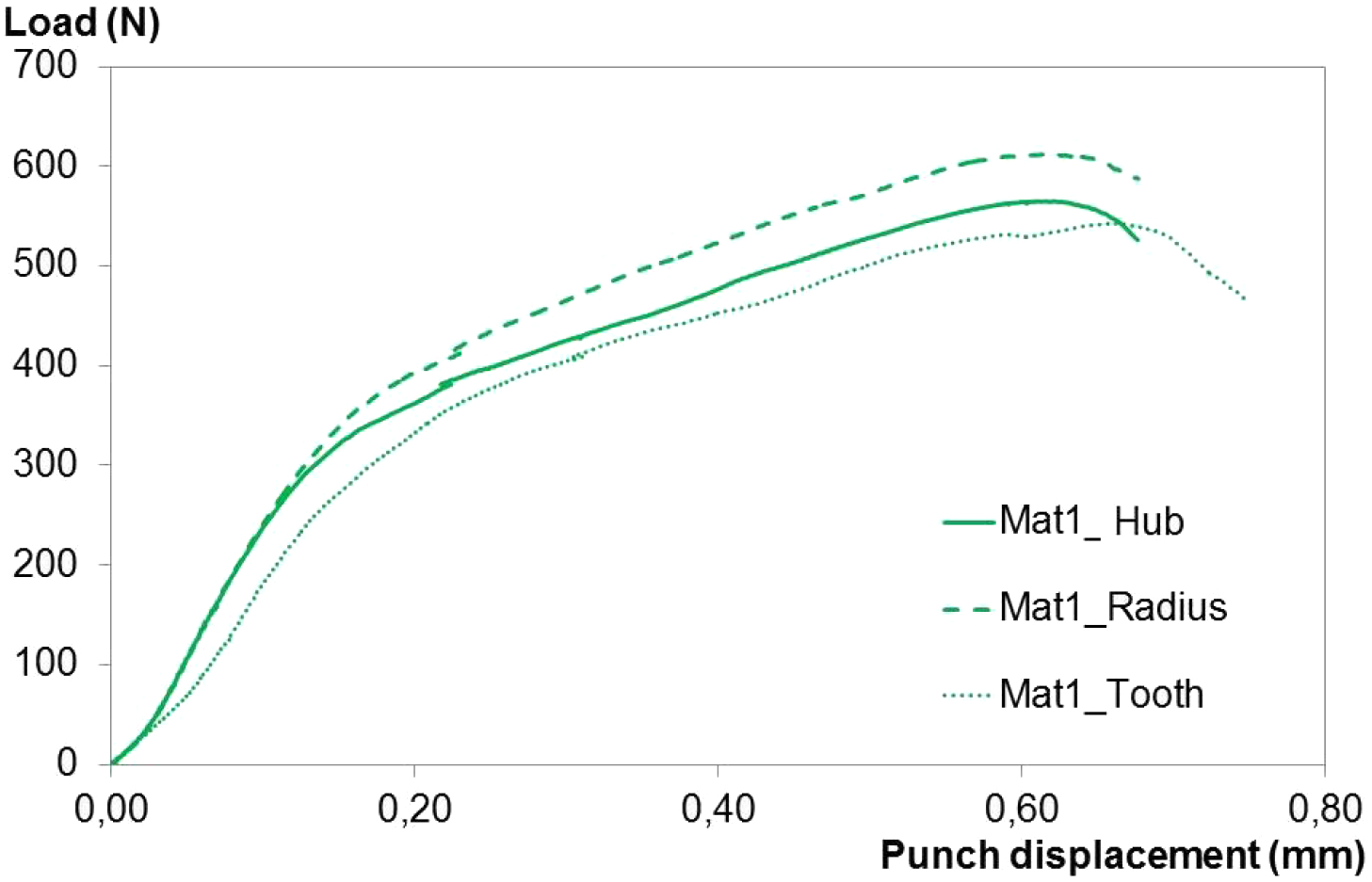
SPT curves from Mat 1 (synchroniser hub)
Hub's SPT parameters and estimated tensile properties
Tensile properties obtained from the SPT parameters for the synchroniser hubs proceeding from Mat1 and Mat1+T
Conclusions
The applicability of the Small Punch Test to mechanically characterise powder metal products has been demonstrated and valid correlations have been proposed in order to obtain their tensile mechanical properties from the typical SPT parameters.
By means of the proposed correlations, the tensile properties of different parts (hub, radius, tooth) of synchroniser hubs manufactured using three different powders were determined and also the effects due to modifications of manufacturing parameters on the mechanical properties of the aforementioned hubs.