
Abstract
In the present paper, SiO2 glass ceramic and Ti–6Al–4V alloy were successfully brazed with Ag–21Cu–4·5Ti active braze alloy. The interfacial microstructure and evolution course of SiO2 glass ceramic/Ti–6Al–4V joint were studied in detail. According to the experimental results, active element Ti plays a quite important role in the formation of reaction layers on the joint interface. The reaction products of the joint are TiSi2, Ti4O7, TiCu, Cu2Ti4O and Ti2Cu respectively. The interface evolution can be generally described by four stages, which are solution and diffusion of atoms, reaction among atoms, formation of reaction layers and precipitation of solid solution layers respectively.
Introduction
Glass ceramics present high flexural strength, significant fracture toughness, good resistance of wear, and have been increasingly applied in aerospace, optics, bioengineering and electronics industrial fields.1–4 In most cases, ceramics are joined to themselves or other materials due to the difficulties of fabricating into complicated components. Different kinds of joining techniques for ceramics have been documented in the last few years.5–11 However, joining of SiO2 glass ceramics to alloys in which SiO2 glass ceramic is bonded as parent material but not filler material is rarely reported. Therefore, the authors have to refer to the joining methods for traditional ceramics. Active brazing is considered as a promising technology for bonding SiO2 glass ceramic and Ti–6Al–4V alloy owing to the improved wettability and joining quality by active elements in braze alloy.
Because the joining quality depends strongly on the reaction products of the joint, the interfacial microstructure and evolution course of SiO2 glass ceramic/Ti–6Al–4V alloy joint brazed with commercial Ag–21Cu–4·5Ti braze alloy are comprehensively studied in the present work.
Experimental procedure
SiO2 glass ceramic and Ti–6Al–4V alloy were brazed in the experiment. For the convenience, they are respectively marked as SiO2 and TC4 in the following figures. Commercially obtained Ag–21Cu–4·5Ti braze alloy foil was 50 μm in thickness. SiO2 glass ceramic and Ti–6Al–4V alloy were supplied as blocks of 8×5×5 and 35×10×3·5 mm respectively. Figure 1 demonstrates the microstructure of SiO2 glass ceramic by TEM, and its chemical composition is 74·52SiO2–23·4Al2O3–2·08K2O. Each surface was polished by SiC papers up to 1200 grit and ultrasonically cleaned by acetone before brazing.
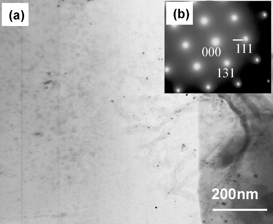
a TEM image; b electron diffraction pattern of SiO2 glass ceramic
The brazing was carried out in a vacuum furnace (Centorr-3520). Experiments were performed at different temperatures (850–1000°C) for several holding times (1–30 min). After joining, interfacial microstructure was examined with S4700 scanning electron microscope (SEM) equipped with an energy dispersive spectrometer (EDS) and an electron probe X-ray microanalysis (EPMA). The microstructure of reaction layer at ceramic side was identified by TEM analysis (Philips CM12).
Results and discussion
Interfacial structure of brazed joint of SiO2 glass ceramic/AgCuTi/Ti–6Al–4V alloy
To value the wettability of AgCuTi on SiO2 glass ceramic, the wetting experiment was performed in vacuum circumstances, the result of which is given in Fig. 2. It can be seen from Fig. 2 that AgCuTi alloy spreads well on the base material at 880°C, which shows that AgCuTi alloy has good wettability on SiO2 glass ceramic.
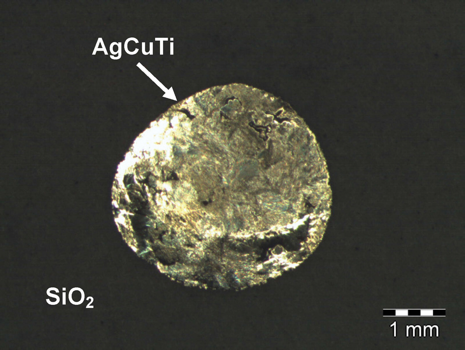
Wetting of AgCuTi braze alloy on SiO2 glass ceramic at 880°C
Figure 3 shows the microstructure of SiO2 glass ceramic/Ti–6Al–4V interface brazed at 880°C for 5 min. As shown in Fig. 3a, the whole interface can be divided into four layers on the interface. A thin reaction layer forms between SiO2 and AgCuTi filler alloy (marked by A). The region composed of white matrix and grey phase is marked by B. Near Ti–6Al–4V, the thick grey reaction layer is labelled by C, and the eutectic reaction layer beside Ti–6Al–4V alloy is marked by D.
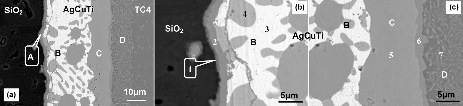
a joint interface; b; SiO2 glass ceramic/Ag–Cu–Ti interface; c Ag–Cu–Ti/Ti–6Al–4V interface
To identify the reaction products on the interface, magnifications of SiO2/AgCuTi interface and AgCuTi/Ti–6Al–4V interface are presented in Fig. 3b and c . Table 1 gives the average chemical compositions and possible reaction products in the joint brazed at 880°C for 5 min.
Average chemical compositions of reaction products on the joint at 880°C for 5 min, at-
As shown in Fig. 3b and Table 1, region 1 in layer A is rich in Ti, Si and O. According to TEM image and electron diffraction patterns of interfacial layer (site 1) in Fig. 4 and the reaction products of the brazed SiO2 glass ceramic/AgCuTi/steel joint, 12 region 1 is composed of TiSi2+Ti4O7. It can be seen from Table 1 that region 2 in layer A is rich in Ti, Cu and O. Reference mentioned that when Ti based alloy was brazed to Al2O3 by a Ag–Cu–Ti braze alloy, concentration of Ti in the joint was very high, which easily led to the formation of Cu2Ti4O and TixCuy on the interface (Ti activity diagram corresponding to the Ti–Cu–O ternary at 945°C is shown in Fig. 5). 13 It can be deduced from Fig. 5 and Table 1 that region 2 in layer A is composed of TiCu+Cu2Ti4O.
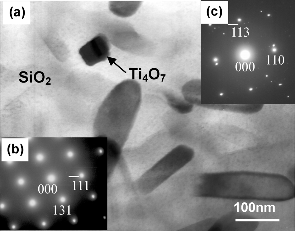
a morphology of interfacial layer (site 1); b electron diffraction pattern of SiO2 glass ceramic; c electron diffraction pattern of interfacial product Ti4O7
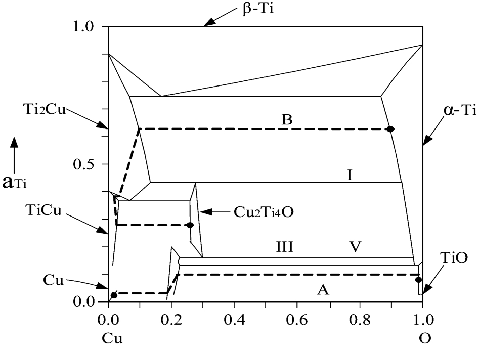
Ti activity diagram corresponding to Ti–Cu–O ternary at 945°C 13
It also can be known from Table 1 that the white phase (region 3) in Fig. 3 is Ag based solid solution [Ag(s.s)], while the black phase (region 4) is identified to be Cu based solid solution [Cu(s.s)]. On AgCuTi/Ti–6Al–4V interface, as shown in Fig. 3c, region 5 in layer C is considered to be TiCu by EDS analysis, and thin Ti2Cu layer (region 6) is found between layers C and D because much Ti in Ti–6Al–4V alloy solutes to the interface. Based on Table 1, eutectic reaction layer (layer D) exists between Ti2Cu (region 6) and Ti–6Al–4V alloy, which is composed of Ti(s.s) (black strips)+Ti2Cu (white matrix). Therefore, the interface structure of the SiO2 glass ceramic/Ti–6Al–4V joint brazed at 880°C for 5 min can be depicted as SiO2/TiSi2+Ti4O7/TiCu+Cu2Ti4O/Ag(s.s)+Cu(s.s)/TiCu/Ti2Cu/Ti(s.s)+Ti2Cu/Ti–6Al–4V. Average shear strength of joints brazed under this condition can reach 19 MPa, which is nearly 80 of that of SiO2 base material.
Interface evolution of brazed SiO2 glass ceramic/AgCuTi/Ti–6Al–4V alloy joint
To explain the interface evolution mechanism of the brazed SiO2/AgCuTi/Ti–6Al–4V alloy joint, Fig. 6 presents the interface evolution model for the joint. It can be seen from Fig. 6 that the whole reaction process can be approximately divided into the following four periods.
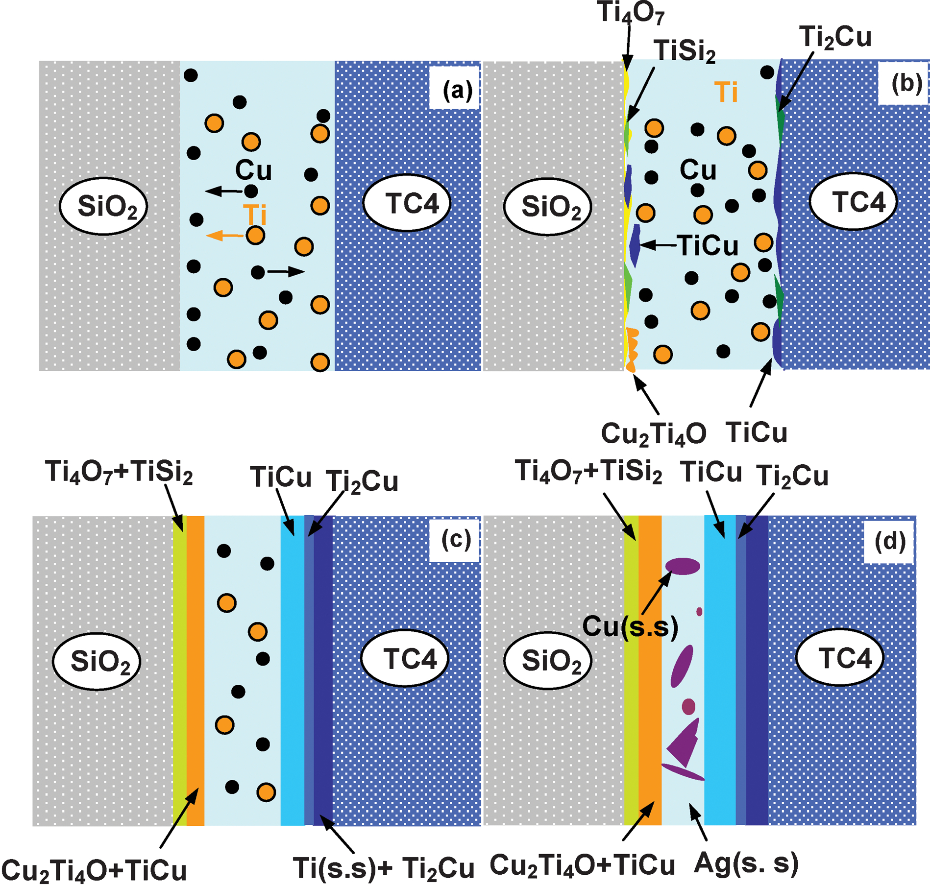
a atom's motion; b, c formation of reaction layers; d precipitation of Ag(s.s)+Cu(s.s), thickening of reaction layers
First, when the brazing temperature is up to the melting point of AgCuTi braze alloy, the braze alloy melts. After that, element Cu in the liquid braze alloy migrates to both of SiO2/AgCuTi and AgCuTi/Ti–6Al–4V interfaces due to the existence of element concentration gradient. Besides, on AgCuTi/Ti–6Al–4V interfaces, element Ti in Ti–6Al–4V solutes into the liquid braze alloy and diffuses to SiO2 glass ceramic/AgCuTi interface (Fig. 6a).
In the second period (Fig. 6b), with increasing brazing temperature, Ti reacts with SiO2 glass ceramic, which leads to the appearance of Ti4O7 and TiSi2 at the SiO2/AgCuTi interface, as depicted in equation (1). On the other side, TiCu is formed at the AgCuTi/Ti–6Al–4V alloy interface owing to the reaction between Ti and Cu in equation (2)


Conclusions
Brazing of SiO2 glass ceramic to Ti–6Al–4V alloy has been successfully achieved. The interface structure is SiO2/TiSi2+Ti4O7/TiCu+Cu2Ti4O/Ag(s.s)+Cu(s.s)/TiCu/Ti2Cu/Ti(s.s)+Ti2Cu/Ti–6Al–4V from SiO2 glass ceramic to Ti–6Al–4V alloy. The whole interface evolution process can be divided into four stages, which are the solution and diffusion of atoms after the melting of braze alloy, reaction among atoms with increasing temperature, growth of TiSi2+Ti4O7 layer (region 1 in layer A), TiCu+Cu2Ti4O layer (region 2 in layer A), TiCu layer (layer C), Ti2Cu layer (region 6) and Ti(s.s)+Ti2Cu layer (layer D) during holding temperature and cooling, and precipitation of Ag(s.s)+Cu(s.s) layer (layer B).
Footnotes
Acknowledgements
This work was supported by the National Natural Foundation of Science (no. 50705022) and Program of Excellent Team in Harbin Institute of Technology.