
Abstract
The main objective of this research work was to develop Ni–TiC and Ni–(Ti, W)C composite powders for high velocity oxy-fuel (HVOF) coating and characterisation of the coatings. For this purpose, two kind of composite powders were produced by the self-propagation high temperature synthesis (SHS) method (Ni–TiC and Ni–(Ti, W)C composites). Subsequently composite powders were used as feedstock for HVOF coating. Also, as reference sample, similar coating was prepared using Ni and TiC powders mixture. Samples were characterised by X-ray diffractometer (XRD), scanning electron microscope (SEM), energy dispersive spectroscopy and adhesion tests. According to results, Ni–TiC and Ni–(Ti, W)C composite powders were developed via the SHS method yield appropriate HVOF coatings with dense, homogeneous, rounded, fused carbide distribution as well as suitable adhesive strength and high crack resistance. With an initial powder mixture of Ni and TiC for HVOF coating, TiC oxidation and Ti2O3 formation occurred; the microstructure of the coating was heterogeneous and irregular morphology having sharp facets. This coating had a low density and low adhesive strength and low crack resistance.
Introduction
Combustion synthesis, also known as self-propagation high temperature synthesis (SHS), is a favoured method for producing ceramics, composites and intermetallics. According to this method, a compacted pellet of reactant materials is ignited by an external heating source. Heat released from the exothermic reactions creates a self-propagation combustion front. Passing over this combustion wave, reactant materials convert to final products. The high production rate and low energy consumption are some of the advantages of the method.1,2 The equipment required for the SHS process is simple and this dramatically reduces the cost of primary production.3 Self-propagation high temperature synthesis process is employed for production of X–TiC powders (composite powders of TiC as hard phase with a metallic phase as binder or matrix). These powders are favourable materials for thermal spray coatings.
Thermal spraying is an ever expanding area in surface engineering technology, which involves the deposition of molten or semimolten droplets of powders on a substrate to form a coating.4,5 High velocity oxy-fuel (HVOF) thermal spraying is characterised by a high flame velocity up to 2000 m s−1.6 In the HVOF thermal spray technology, oxygen and liquid fuel are combusted under high pressure in a chamber and the combustion products are accelerated through a converging–diverging nozzle.7–9 The powder, fed into the hot stream of gases, can be oxidised due to hot temperature and oxidising condition in HVOF process. X–TiC powders (composite powders of TiC as hard phase with a metallic phase as binder or matrix) produced by SHS method can be used.
On the other hand, the performance of HVOF coatings also strongly depends on the coating microstructure which, in turn, depends on the characteristics of powder feedstock.
Titanium carbide has a high hardness and can be readily compounded with tungsten carbide [(Ti, W)C]. The novel and additional characteristic of this double carbide is its higher thermal stability for high temperature applications.1 In addition, (Ti, W)C powder and cermets have been demanded by hard material industries since the 1980s.10,11
Despite the fact that numerous recent studies have been focused on the production and examination of the microstructure of thermal sprayed coatings of TiC and (Ti, W)C, an adequate understanding of this topic is yet to be obtained.2,3,12 The present study aims to investigate the development of Ni–TiC and Ni–(Ti, W)C composites powders to be used as suitable feedstock powder HVOF coatings.
Material and methods
Ti, Ni, W, graphite and TiC powders at purity levels shown in Table 1 were used as starting materials. Two different composite powders, namely, Ni–TiC and Ni–(Ti, W)C, were prepared using the SHS method. The atomic ratio and chemical composition of the starting materials for the production of the above composite powders are listed in Table 2.
Purity of starting materials
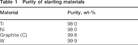
Atomic ratio and chemical composition of samples
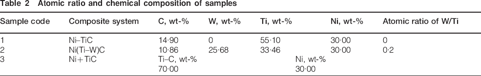
To preparation of SHS samples a die with 1·1 cm in diameter was used and green pellets of 50–60% theoretical density were produced by pressing of starting powder mixtures. The ignition of the samples was carried out under the argon atmosphere using a setup schematically shown in Fig. 1.
Setup used for sample ignition in SHS method3
After combustion was completed the resultant sponge materials were crushed and classified to achieve the desired powder particle size ranges for HVOF thermal spraying. As a reference sample, Ni and TiC powders were also mixed and subjected to HVOF coating. This resulted in the use of three kinds of powders for HVOF coating: two powders were produced by the SHS method [Ni–TiC and Ni–(Ti, W)C composites] and subsequently used for HVOF coating operations, while the other sample of physically mixed powder was directly used for HVOF coating. All powders were sprayed on the conventional carbon steel cylinders (25 mm in diameter, 25 mm in height, and machined from bar stock) with prepared surfaces for HVOF spraying on flat surface of cylinders. All coating samples were sprayed under the optimum HVOF thermal spray condition based on spray efficiency of METJET3 (made in England) coating instrument. Spraying conditions were: oxygen rate: 0·0138 m3 s−1, fuel type: ATK (one kind of airplane fuels), fuel rate: 4·16×10−6 m3 s−1, working distance (shortest distance between end of gun and sample surface): 0·35 m, chamber pressure: 7×10⁵ Pa. These conditions were kept constant for all the samples. Upon spraying, the samples were subjected to structural characterisation and measurement of the adhesive strength of the coatings.
Adhesion strength of coatings was evaluated according to the ASTM-C633 standard.8 In this test, the cylinder coated sample is glued (with 95 MPa adhesive tensile strength) onto an uncoated identical counterpart that is just grit blasted and then tested in a tension testing machine. The value of the tensile load, at which the separation of the coated–uncoated parts occurs, is taken as the adhesion value and repeated for tree times to get statistically relevant results. The failure region indicates the characteristics of the failure.
Crack propagation characteristics were determined by indenting the cross-section of coatings at the coating and substrate interface. This test was carried out using a microhardness Vickers indenter under identical conditions (50 N loads for 15 s, indention direction: parallel to the interface) for all the samples.
Microstructural characterisation of the samples was accomplished by the following techniques: X-ray diffraction (XRD) on a Philips (MPD-X'PERT) System X-ray diffractometer (Cu Kα radiation, λ = 0·154056 nm); scanning electron microscope (SEM) on a Philips (XL30 SERIES) system. Microanalysis of the samples was carried out on an energy dispersive spectroscopy (EDS) analyser (EDAX) (Five areas were randomly chosen for EDS analysis of the chemical composition of various phases).
Results and discussion
Composite synthesis
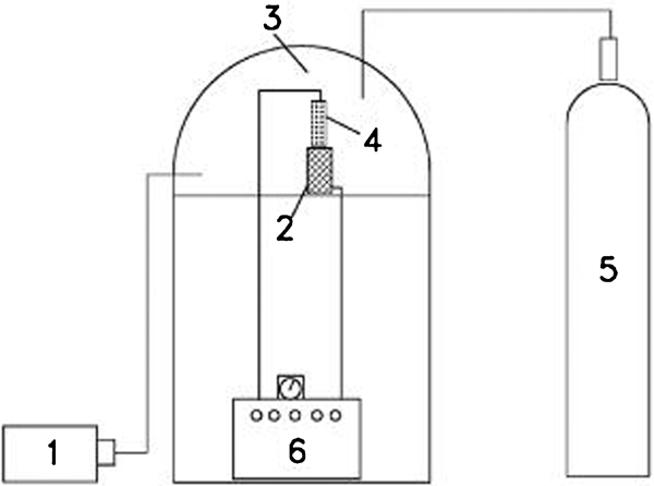
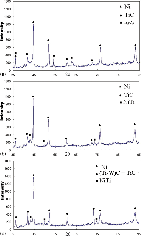
Phase analysis of the composite materials, produced by SHS, was carried out using XRD method. Figure 2 shows the XRD patterns of the Ni–TiC and Ni(Ti–W)C samples. Based on these XRD patterns, the presence of Ni and TiC phases in the Ni–TiC feedstock and, similarly, the presence of Ni and (Ti, W)C phases in the Ni(Ti–W)C feedstock were confirmed. It should be noted that tungsten atoms were replaced in the TiC lattice to produce (Ti, W)C. The production of (Ti, W)C was confirmed by lattice parameter measurement and EDS analysis as has also been reported elsewhere.3
X-ray diffraction patterns of SHS produced feedstocks
Figure 3 is SE–SEM image of feedstock powders after mechanical crushing. It is clear that the powders have generally the same surface morphology. They also have irregular shapes due to the crushing operation after the SHS process. The powders were finally screened to achieve the desired powder particle size ranges for HVOF thermal spray coating (about 32–45 μm).
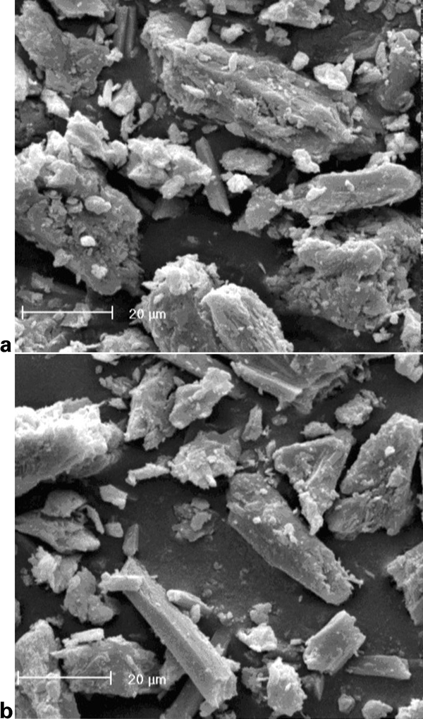
Image (SE–SEM) of feedstock powders after mechanical crushing
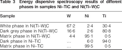
Figure 4 is BSE–SEM images of polished sample of powders. In these micrographs, contrastive differences between the Ni–TiC and Ni(Ti–W)C samples were indicated by their different chemical compositions and phase distributions. The different phases in the micrographs were analysed and EDS results were summarised in Table 3. According to EDS and XRD results, the dark grey phase in both samples is TiC, the white rounded particles in the Ni(Ti–W)C sample are (Ti–W)C, and the matrix phase in both samples is Ni. Therefore, rounded carbides distributed in a metallic matrix appeared in both powders. Size and distribution of the carbides were almost homogeneous and porosities and interfacial gaps could not be seen in particles. These structures could be very interesting for various applications due to the combination of rounded hard phases (lower tension sensitiveness) and ductile metallic phase. The larger size and much more angular morphology of (Ti–W)C particles were happened due to diffusion of tungsten atoms in the TiC lattice in a solid state phase transaction, so the rounded morphology were partially changed. On the other hand, TiC was formed during liquid phase transaction with perfect rounded morphology.13
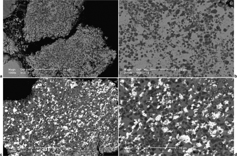
Images (BSE–SEM) of feedstock cross-section
Energy dispersive spectroscopy results of different phases in samples Ni–TiC and Ni(Ti–W)C
The presence of particulate carbides is evidence of solution precipitation mechanism (the reactants becoming molten during the SHS process). In the Ni–TiC sample, liquid Ni is formed and enriched with Ti and C so that TiC precipitated from the liquid upon cooling. Furthermore, in the Ni(Ti–W)C sample, the presence of tungsten could have lowered the adiabatic temperature of SHS which may have encouraged the replacement of Ti atoms by W atoms to form (Ti–W)C. The presence of small (less than 5% and so invisible in the XRD pattern) amounts of metallic tungsten in the matrix could be the result of incomplete dissolution of the original tungsten.
HVOF coated sample characterisation
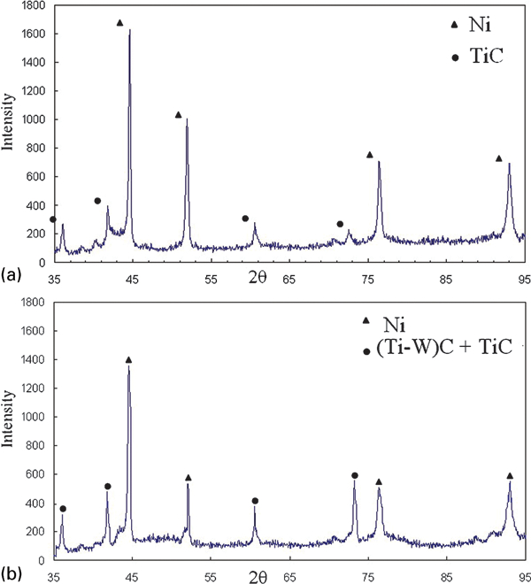
After optimisation of the HVOF parameters, three coating were produced using Ni+TiC, Ni–TiC and Ni–(Ti, W)C powders. Figure 5 shows the XRD patterns of these samples (coatings). Base on these XRD patterns, formation of a significant amount of Ti2O3 in coating 1 (Ni+TiC sample) is evident which is a result of oxidation of TiC during the spraying. In the case of coating 2 (Ni–TiC sample) and coating 3 [Ni–(Ti, W)C sample] oxidation of TiC has not occurred. Production of some NiTi intermetallics during thermal spraying in coating 2 and 3 is also a favourable effect.
X-ray diffraction patterns of HVOF coatings
The SE–SEM image of the as sprayed top surface of HVOF coated Ni+TiC, Ni–TiC and Ni(Ti–W)C samples is shown in Fig. 6. As can be seen, the original powders were molten and fused onto the surface and rounded particles of (Ti–W)C were observed. An irregular morphology having sharp facets is observed in the Ni+TiC sample. While dense and almost complete self-agglomerated in the SHS prepared powders for HVOF is seen [the Ni–TiC and Ni(Ti–W)C samples]. Based on Fig. 6, the roughness of the HVOF sprayed coatings in the Ni(Ti–W)C sample is less than that in the Ni–TiC sample and the coating of the Ni+TiC sample is porous and rough.
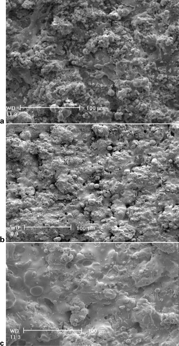
Image (SE–SEM) of as sprayed top surface of HVOF coated
The typical cross-sectional microstructure of the coating systems can be observed in the BSE micrographs in Fig. 7. Based on these micrographs, the coatings of the Ni–TiC and Ni–(Ti–W)C samples are more homogeneous and dense with low oxidation whereas that of the Ni+TiC sample was not and some oxidised layer could be seen in it (the dark phase in the micrograph). In fact, lack of porosity and interfacial gaps between carbide particles and Ni phase results in a denser coating containing lower amounts of oxides. Based on the XRD pattern of HVOF coated sample, the oxidised layers must be Ti2O3. The carbide observed in the coating 3 was similar in morphology to that found in the feedstock powder. All coatings had thicknesses of about 200–250 μm.
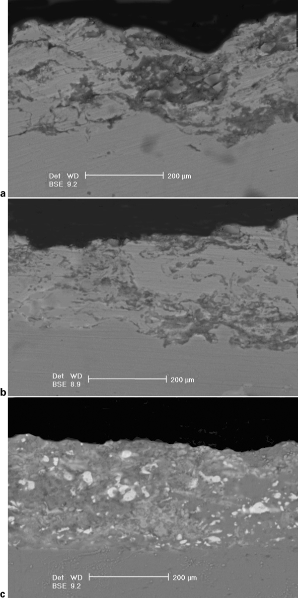
Images (BSE) of cross-sectional microstructure of coatings
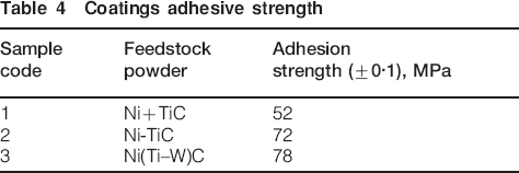
Figure 8 exhibits the fracture surfaces of adhesion tested samples (ASTM-C-633). In these pictures, bright areas correspond to failure at the interface and dark regions represent the area where failure occurred in the coatings. According to these pictures, the samples show distinctive failure behaviours. A local failure, with bright contrast, can be seen in Fig. 8a. Local coating detachment in the Ni+TiC sample could have occurred due to the homogeneity of coating and insufficient bonding of carbide particles to the metal matrix in the carbide aggregated region. Furthermore, interlocking (and then adhesion) increases with an increase in the density of coating. Consequently, the higher densities of Ni–TiC and Ni (Ti–W)C have led to a better adhesive behaviour of the coatings. This could partially explain the distinct adhesion values (Table 4). The adhesion value for Ni(Ti–W)C coating is grater than Ni–TiC coating by about 10% so better quality of this coating were expected in use. This can be due to denser microstructure of Ni(Ti, W)C coating as evident from Fig. 7c.
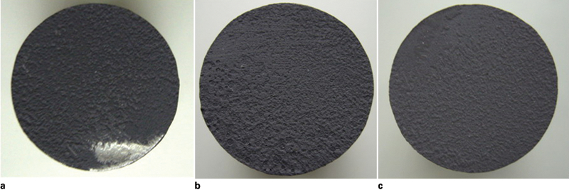
Fractured surfaces of adhesion tested samples (ASTM-C-633)
Coatings adhesive strength
The typical crack indentation behaviour of coatings at the interface is shown in Fig. 9. As seen in Fig. 9a, a crack was generated from a corner of the indentation and propagated into the coating, unlike the interface (the dashed circle). The crack pattern induced by indentation of the Ni+TiC is characteristic of an anisotropic medium due to a heterogeneous hard and metallic phase distribution in the coating. As seen in the other pictures in Fig. 9, no cracking occurred in the coating 2 and 3 [Ni–TiC and Ni–(Ti, W)C samples]; it could be concluded, therefore, that the homogeneously distributed, semimolten carbide particles embedded in the microstructure of Ni–TiC and Ni–(Ti, W)C coatings tend to show higher crack resistance and crack arrest properties (if they have been formed during Vickers indentations). Hence, the superior crack generation and propagation resistance of the SHS synthesised HVOF sprayed coating was attributed to the good bonding between TiC and Ni powders produced by SHS.
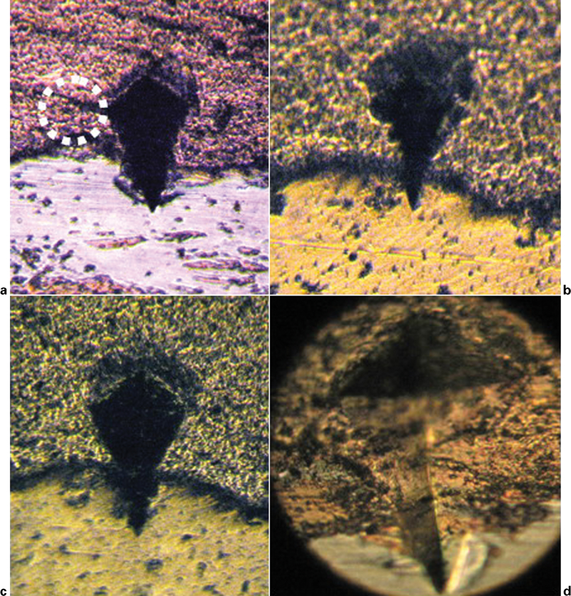
Indentation of coating interfaces
Conclusions
1. Ni–TiC and Ni–(Ti, W)C composite powders developed via the SHS method yield appropriate HVOF coatings with dense, homogeneous, rounded, fused carbide distribution as well as suitable adhesive strength and high crack resistance.
2. With an initial powder mixture of Ni and TiC for HVOF coating, TiC oxidation and Ti2O3 formation occurred; the microstructure of the coating was heterogeneous with some oxidised layers and irregular morphology having sharp facets; this coating had a low density and low adhesive and crack resistance.
3. Among the samples investigated, the SHS produced, HVOF coated Ni–(Ti, W)C composite had the best characteristics of homogeneity, density, adhesion and crack resistance.