
Abstract
Nickel based Colmonoy 6 (conforming to AWS NiCr–C) hardfacing alloy finds application in hardfacing of various components made of austenitic stainless steel (SS) used in fast reactors. Owing to considerable difference in melting points of the SS and Colmonoy 6 alloys, significant dilution from substrate occurs during hardfacing using gas tungsten arc welding process. Dilution has a significant effect on microstructure, hardness and wear resistance of the deposit. To overcome the adverse effects of dilution on the hardness and, hence, the wear resistance of the deposit, often, the minimum thickness specified for the deposit on hardfaced components is high, which in turn increases the susceptibility of the deposit to cracking during deposition. In the present investigation, microstructure of different layers of multilayer Colmonoy 6 deposits on 316LN SS is characterised by optical and scanning electron microscopy, and the correlation between hardness and microstructure of the individual layers with dilution from the base metal has been established. The dilution from the base material is the highest in the first layer, and it progressively decreases in the subsequent layers. With progressive decrease in dilution, the precipitate fraction increases from about 16 to 20% from the first to the fifth deposit layers. This is accompanied by hardness increase from about 480 to 800 HV. The precipitates in the deposit consist of both borides and carbides, with the boride content varying more with dilution than the carbide content. The boride fraction increased from 5 to 8% with a decrease in dilution; however, layer to layer variation in carbide fraction was only marginal at about 11–12%. High dilution from the base material suppresses the formation of borides in the deposit and is responsible for low hardness of the deposit diluted with the austenitic SS compared to those of the undiluted deposit.
Introduction
In fast reactors, many austenitic stainless steel (SS) components are in contact under stress in flowing liquid sodium environment at temperatures of up to 823 K. As flowing sodium removes the oxide film that is normally present on metallic surfaces, static contact between the mating surfaces for long duration can lead to self-welding of these surfaces. Subsequent relative movement between components can result in galling. Hence, hardfacing of such components by nickel or cobalt based alloys is a common practice for the improvement of resistance to self-welding and galling. Although Co based Stellite alloys, possessing excellent resistance to wear and corrosion at high temperature, 1 are extensively used as a hardfacing material in high temperature applications, induced radioactivity from transmuted Co60 isotope formed in a nuclear reactor environment is hazardous to personnel involved in handling, maintenance and decommissioning of components hardfaced using these alloys.2,3 This deleterious effect coupled with global scarcity and high cost of cobalt 4 necessitated identifying alternate hardfacing alloys.
Among Ni based alloys, Colmonoy grades are potential replacement for Co based Stellite alloys for providing adequate abrasive and adhesive wear resistance, derived from its high content of chromium and boron. 5 The hardness of Colmonoy alloys is higher than that of Stellite alloys, which is attributed to the presence of chromium carbides and chromium borides present in the deposit, instead of only carbide precipitates in Stellite.4,6 However, the higher stacking fault energy of the Ni matrix than that of the Co matrix of Stellite alloys results in lower number of impeding stacking faults and increased tendency to cross slip and galling, thereby adversely affecting the wear resistance of the deposit. 7 This can be taken care of by the addition of chromium and iron. 8
Gas tungsten arc welding (GTAW) is a conventional method for hardface deposition of Colmonoy on SS components. However, GTAW deposited Colmonoy suffers from significant dilution by the substrate material due to a large difference in the melting temperature range between these two alloys. 9 Dilution from the base metal affects the microstructure of the deposit. Dilution is the highest in the first layer, which is deposited on the base metal, and it decreases progressively in the subsequent layers that are made on the deposit. Hence, substantial alteration in microstructure across the cross-section of the deposit is expected. This ultimately results in variation in hardness and wear resistance across the deposit.10,11 Hence, it is necessary to evaluate the influence of dilution on the microstructure and hardness in order to qualify the wear resistance performance of the deposit.
Many investigators4,5,8,12 identified blocky type chromium boride and needle-like chromium carbide precipitates as the major precipitates in Colmonoy 6 deposit that contributes to its hardness. Studies on microstructural developments in Colmonoy 6 deposited by laser cladding and thermal spraying techniques13–17 are also available. Some studies have also shown that dilution from the base metal affects the hardness and wear properties of the deposit. However, no systematic study is reported on how dilution from the base metal causes the hardness and microstructural change in this Colmonoy deposit.
In the present investigation, an attempt has been made to characterise the microstructure of different layers (having different levels of dilution) of Colmonoy 6 deposit produced by GTAW process on austenitic SS, using optical, scanning electron microscopy (SEM) and energy dispersive X-ray spectroscopy (EDS). Precipitate fraction, average size and size range of the precipitates in each layer have also been estimated using image analysis software. The paper aims to correlate variations observed in the fraction, morphology and size of the precipitates in different layers of the deposit that has been diluted from the austenitic SS substrate.
Experimental
Hardfacing alloy deposition
Ni based hardfacing alloy Colmonoy 6 was deposited on 316LN SS plate of size 125×75×30 mm using the GTAW method. The 316LN SS based plate was preheated to 673 K, and after the hardfacing alloy deposition, the deposit was cooled in vermiculite powder to ensure slow cooling and avoid risk of cracking. Separate deposits of Colmonoy 6 (of size 100×15 mm), with the number of layers varying from 1 to 5, were produced in five different 316LN SS based plates, with the second layer deposited over the first layer, third layer over the second layer and so on. For these multilayer deposits, the interpass temperature was maintained at 673 K so as to ensure identical cooling conditions. All further experiments, such as microstructural examination, hardness measurement and EDS studies, were conducted on the top surface of the layer so as to avoid the mixed zone of two layers during the investigation (Fig. 1). To obtain undiluted deposit, Colmonoy 6 bare rod was melted on a 25 mm thick pure water cooled copper plate using the GTAW process. The molten metal solidified immediately on the surface without melting the copper block. The nominal chemical composition of pure Colmonoy 6 hardface deposit and 316LN SS is given in Table 1, while details of welding conditions employed in the present study are listed in Table 2.
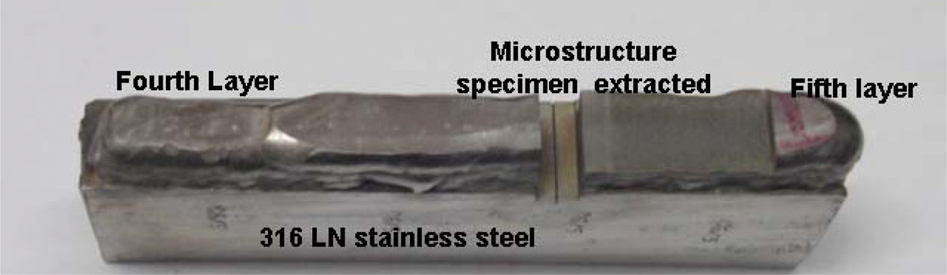
Colmonoy 6 hardface deposit on 316LN SS
Nominal chemical compositions of 316LN SS and Colmonoy 6, wt-%
Welding conditions used during deposition of Colmonoy 6
Microstructural characterisation of hardface deposits
Two sets of specimens of size 10×10×2 mm comprising of undiluted Colmonoy 6 and the top surface of the five different layered deposits were polished by standard metallography techniques. Microhardness indentations were made on the specimens for identifying locations for metallography before and after etching. Micrographs were taken at two different magnifications of ×200 and ×500, and the area fraction of precipitates, their morphology and size distributions, etc. were estimated using the ImagePro software from 100 micrographs of each deposit layer. During optical microscopy, the blocky precipitates were observed in the unetched condition, while both the blocky and needle-like precipitates were observed after etching with Murakami reagent; Fig. 2 shows micrographs of the same location before and after etching. Hence, the area fraction of total precipitates was estimated by image analysis, and the difference in the area fraction of both the precipitates and the blocky precipitates gives the area fraction of the needle-like precipitates. As there is a large variation in precipitate morphology of the different layers, the aspect ratio of precipitates was kept fixed for each layer during image analysis, and the area of precipitates was normalised to a circular morphology in which the size of precipitates is represented as the diameter of the normalised circle. The size distribution of precipitates was estimated by selecting different size ranges (in micrometre) measuring the percentage area of precipitates for a particular size range.
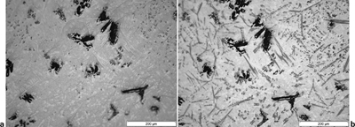
a unetched and b etched samples of third layer deposit for image analysis
The metallography samples in the unetched condition were further examined under SEM. Using backscattered mode of operation, it was possible to achieve different contrasts for different types of precipitates. Energy dispersive spectra for matrix and precipitates in different layers were also taken. Assuming that most of the carbon and boron in the alloy are in the precipitates and that the matrix is free of these elements, approximate composition of the matrix for each layer was estimated from EDS analysis. Hardness measurements were carried using Vickers hardness tester at 10 kg load.
Results
Microstructure
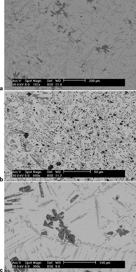
Figure 3 shows microstructures of undiluted Colmonoy 6 deposit on copper and of the different layers of deposit on austenitic SS. As already mentioned, only one type of precipitates is revealed under unetched condition. The size, morphology and distribution of this precipitate vary widely in the first, second and third layers. In the first layer, where maximum dilution from the base metal occurs, both the size and area fraction of the precipitates are small. In the second layer, there is an increase in both the size and area fraction of the precipitates. From the third to the fifth layers, the morphology and distribution of the precipitates are similar, with marginal increase in the size of precipitates with increase in the number of deposit layers. With minimum dilution in the fifth layer on SS and no dilution in the deposit on copper, it was expected that the microstructure of these deposits would be similar. However, Fig. 3a and f shows that their microstructures are quite different, as the cooling rate for the undiluted deposit on copper would be significantly higher than deposits made on SS (with preheat temperature of 673 K).
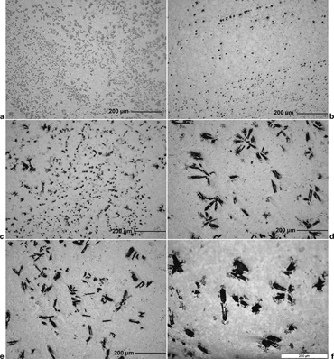
Microstructures of different layers of Colmonoy 6 hardface deposit under unetched condition
Figure 4 shows the microstructure of undiluted Colmonoy 6 on copper and of the second, third and fifth layer deposits on SS after etching with Murakami reagent. Additional etching reveals precipitates with needle-like morphology and also those formed in the interdendritic region. The size of needle-like precipitates also varies with deposit layer, with the average size being minimum in the first layer and maximum in the fifth layer.
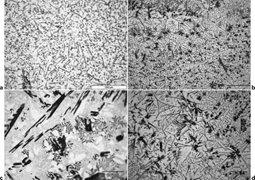
Microstructures of different layers of Colmonoy 6 hardface deposit under etched condition
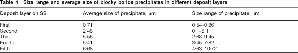
The area fraction of blocky and total precipitates was estimated from unetched and etched specimens respectively by image analysis of a large number of micrographs of each deposit layer, and the fraction of predominantly needle-like precipitates (including some interdendritic precipitates) was calculated by subtracting the fraction of blocky precipitates from the total precipitates (Table 3). The fraction of blocky and total precipitates increased from the first to the third layers, beyond which there was no significant change in the fourth and fifth layers. On the other hand, the fraction of needle-like precipitates remained almost unchanged at ∼12% for the different layers of the deposit, except for a marginal increase from the first to the second layers.
Layer wise variation of precipitation in Colmonoy 6 deposit
As the precipitate size was very small and contrast poor (Fig. 3a), the area fraction of precipitates could not be estimated in the unetched condition in the undiluted deposit on copper. However, on etching, the contrast improved (Fig. 4a), and the area fraction of total precipitates could be estimated by image analysis to be ∼15%, which was lower than that in the fifth layer deposit on SS.
As wide variation in size, distribution and morphology of the blocky precipitates were observed in the different deposit layers, the size range and average size of these blocky precipitates were also estimated by image analysis (Table 4). The microstructures in Fig. 3b–f show that the average size of the blocky precipitate increased significantly from 0·7 to 5·6 μm from the first to the third layers, beyond which the increase was only marginal. The size range of almost all precipitates in the first layer is submicron, while those in the third layer onwards are of several microns, with the second layer deposit containing precipitates of a size varying by more than an order of magnitude.
Size range and average size of blocky boride precipitates in different deposit layers
Scanning electron microscopic images of undiluted Colmonoy 6 deposit on copper and of different deposit layers on SS taken in backscattered image mode on unetched specimens (Fig. 5) show clear contrast difference between blocky precipitates and the needle-like and interdendritic precipitates, indicating that they are of different types. As observed in the optical micrographs, the size and distribution of the blocky precipitates showed wide variation in the first three layers.
Images (SEM) of Colmonoy 6
Dilution of different layers by base metal
The EDS pattern of the matrix of undiluted deposit on copper and of the first and third deposit layers on SS (Fig. 6) shows that, for the deposit on SS, the iron content in the first layer is significantly higher and the nickel content lower than in the deposit made on copper. However, EDS patterns of the third deposit layer on SS and the undiluted deposit on copper are almost similar. This indicates that dilution from the base metal is significantly affecting the composition of the first deposit layer. In the third layer, which is deposited on two layers of previously deposited hardfacing alloy, the dilution is minimal and the matrix composition matches that of the undiluted deposit on copper.
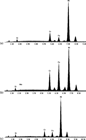
Energy dispersive X-ray spectroscopy results of Colmonoy 6 matrix
The matrix composition of undiluted Colmonoy 6 deposit on copper and of the various deposit layers on SS was estimated from the EDS patterns assuming that carbon and boron that form carbides and borides are absent in the matrix (Table 5). In the first layer, Fe content is as high as 21% against ∼4·8% in the undiluted deposit. Similarly, the Ni content is only ∼59% against ∼83% in the undiluted deposit. In addition, Mo, an element which is absent in the hardfacing alloy but present only in the substrate material, is present in the first deposit layer. The Fe content drastically reduces to ∼9% in the second layer, and in the fifth layer, it is almost similar to that in the undiluted deposit. Variation in Ni content is observed only in the first three layers, and from third layer onwards, the Ni content in the deposit is similar to that of the undiluted deposit on copper. The Cr content in the first layer is also considerably high. It is important to note that Cr content of the matrix of the undiluted deposit made on copper is higher than the matrix Cr content in the fifth deposit layer on SS. Furthermore, Si, which is an alloying element in the hardfacing alloy, is lower in the first deposit layer than in other subsequent deposit layers on SS.
Variations in matrix composition estimated from EDS analysis of Colmonoy 6 in undiluted deposit on copper and in different layers of deposit on SS
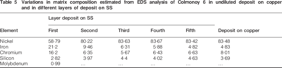
Figure 7 shows the EDS pattern from blocky and needle-like precipitates in the undiluted deposit on copper and the first deposit layer on SS. In addition to Cr, the EDS pattern of the blocky precipitates from the first layer shows presence of Ni, Fe and even some Mo. This clearly indicates that both the matrix and precipitate compositions are altered by dilution from the base metal.
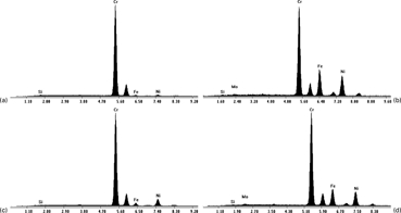
Energy dispersive X-ray spectroscopy results of ‘precipitates in Colmonoy 6
Hardness
Layer to layer variation in hardness of the deposit, shown in Fig. 8, indicates that the hardness of the first layer is only ∼480 HV and that of the third layer is ∼800 HV. In the second layer, hardness recovers substantially to ∼750 HV. It is clear that hardness of the first layer is significantly affected by the dilution of the substrate, and an effect of dilution on deposit hardness is observed even in the second layer. From the third layer onwards, the hardness variation is almost negligible, indicating that there is no dilution of the deposit by the substrate material from third deposit layer onwards. Figure 8 also compares the layer to layer variation in hardness with the area fraction of blocky, needle-like and total precipitate, and almost a one to one correspondence is seen between the area fraction of blocky precipitates and hardness.
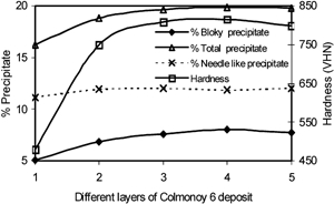
Variation in hardness and amount of precipitation in different layers of Colmonoy 6 deposit on SS
Interestingly, it was observed that the hardness of the undiluted deposit on copper is significantly lower (660 HV) than that of the third, fourth and fifth deposit layer on SS, although dilutions in the former and the latter are minimal.
Discussion
The results presented above clearly confirm that dilution from the substrate austenitic SS significantly affects the microstructure and properties of the deposit. It alters the volume fraction, size, morphology and distribution of precipitates in the matrix. It is known that Colmonoy alloys contain both borides and carbides as precipitates that contribute to their high hardness. Although two types of precipitates differing significantly in their morphology and chemistry could be easily recognised, their identification as borides or carbides has not been conducted in the present study. This is because neither C nor B could be detected easily by EDS, and the major element in both the precipitates is Cr. However, from published literature, it is easy to identify the blocky precipitates as borides and the needle-like precipitates as carbides. Although both carbides and borides are affected by dilution, the present study, using systematic image analysis of the microstructure, reveals that this effect is more for borides than for carbides. As shown in Table 3, there is a clear decrease in the boride content with increase in dilution. In contrast, corresponding variation for carbides is only marginal and confined to the highest level of dilution (in the first layer). Furthermore, variation in the morphology, size and distribution with dilution is also more for borides than for carbides. Average size of the borides in the first layer of deposit (with highest dilution) is an order of magnitude lower than the precipitates observed in the third to fifth layers, which are not affected by the dilution.
It is not clear how dilution from the substrate material, which increases the Fe, Cr and Mo content of the deposit, alters size, distribution and morphology of the precipitates, especially the borides. It is important to note that not only the matrix composition but also the precipitate composition is altered by dilution. As both the type of precipitates are essentially primary precipitates (formed from the liquid metal during solidification), it is reasonable to assume that composition changes in the molten metal caused by the dilution is affecting the nucleation and growth kinetics of the precipitates. Furthermore, dilution increases Cr, the major element present in both borides and carbides, in the melt; it can alter the types of borides (CrB and Cr2B) or carbides (M7C3, M6C or M23C6) formed from the melt.12,13
In this context, it is appropriate to refer to the effect of Mo in modifying the nucleation and growth of the precipitate in hardfacing alloys. Composition of both matrix and precipitate in the first layer shows the presence of Mo. It is reported that morphology of the carbides in Ni based hardfacing alloy is altered by the presence of Mo; deposits without Mo are reported to have carbides with plate-like morphology, and in the deposit with Mo, the morphology of the carbides is different.18–20 Difference in the morphology of the carbides seen in the first layer and the subsequent layers in the present study is also similar. Similarly, in Co based hardfacing alloys, it is reported that Mo can assist the formation of M23C6 in the preference to M7C3.18–20 Thus, it can be concluded that dilution not only changes the composition of the deposit but also affects the thermodynamic stability of the various precipitates and their nucleation and growth kinetics and thus alters the microstructure.
The results clearly bring out, probably for the first time, that the dilution significantly reduces the boride content in the deposit, while the variation in carbide content with dilution is only marginal. A corresponding decrease in hardness with dilution is also observed. It is important to note that weldability of Ni based alloys containing only carbides are very poor, and hence, carbides are partially replaced by borides to achieve the desired hardness and improve the weldability of Ni based hardfacing alloys. Hence, the effect of dilution on the properties of the deposits would be more for Ni based hardfacing alloys than for Co based hardfacing alloys that, in general, do not contain borides.
The practical significance of large variation in both hardness and microstructure of the diluted deposit is important. When hardfacing is carried out using any one of the welding processes, the typical thickness of the deposit would be about 3–4 mm. In most of the cases, the component may have to be machined subsequently to achieve the required dimensional tolerance as, quite often, hardfacing operation causes distortion of the components. During this machining operation, some of the deposit also gets removed, and this removal, due to distortion produced during hardfacing, need not be uniform. Hence, after machining, the deposit thickness remaining could be as low as about 1–2 mm, and this corresponds to the first layer of the deposit that is diluted significantly by the base metal. The wear properties of the diluted deposit have been found to be inferior to that of the undiluted deposit. Hence, often, a minimum deposit thickness has to be specified on finished component that needs to be higher, or a hardfacing process that minimises the dilution may have to be specified to overcome this uncertainty.
In this context, laser surfacing, a relatively new surfacing process, which is being increasingly used for hardfacing application, provides very distinct advantage over GTAW and other conventional processes for hardfacing. By carefully controlling the laser power, the dilution from the substrate can be minimised considerably without resulting in defects like lack of bonding. 21 Furthermore, overall heat input is lower than that of GTAW or plasma transferred arc processes, and this would also reduce the distortion of the component. Both low dilution and low distortion would in turn bring down the minimum thickness of the layer required before machining, thus reducing the total volume of the alloy to be deposited. A major limitation of the laser surfacing is the relatively low deposition rate, but this can be overcome by a considerable extent by automation. Hence, in the near future, laser surfacing would emerge as a viable alternative to conventional surfacing processes.
Comparison of the hardness of the undiluted deposit on copper and that of the fifth deposit layer on SS indicate that hardness is lower for the former. There is no major difference in Fe and Ni contents of these deposits. However, the cooling rate experienced by the deposit on copper is significantly higher than that made on SS. This difference seems to have an effect on the microstructures of the two deposits. In the deposit on copper, the precipitates are very fine, while in the deposit layer on SS, both the carbides and borides are significantly larger. Furthermore, the precipitate content is also lower in the deposit made on copper at ∼15% compared to ∼19% in the fifth deposit layer on SS. It is also important to note that the Cr content is significantly higher at ∼8% in the matrix of this deposit on copper than the 6·5% in the fifth layer of the deposit on SS. These clearly indicate that the precipitate content in the deposit on copper that cooled at a very high rate is lower than that in the deposit on SS that was deposited with high preheat and consequently cooled very slowly. This is the reason for the low hardness of the deposit made on copper. Thus, the results indicate that microstructure and hardness of the deposit of this Ni based hardfacing alloy is also affected by the cooling rate experienced by the deposit. Further studies are necessary to confirm this and its consequences on the properties of the deposit.
Conclusions
The major conclusions from the present study on Ni based Colmonoy 6 hardfacing deposit are the following.
1. Dilution of the deposit by the austenitic SS substrate significantly alters the microstructure and hardness of the hardface deposit.
2. The size, distribution, morphology and volume fraction of the precipitates are altered by the dilution, with the chemistry of the precipitates being also influenced by dilution.
3. The estimated boride and carbide area fractions obtained by image analysis showed that the effect of dilution on borides is larger than that on carbides.
4. It was possible to correlate the variation in the hardness of the deposit with variation in the boride content.
5. Effect of dilution is significant in this Ni based hardfacing alloy that contains both borides and carbides to achieve the desired hardness of the deposit.
6. The cooling rate experienced by the deposit during solidification also influences the hardness and microstructure of the deposit.