
Abstract
Interstitial free (IF) steels having excellent drawing and forming characteristics find extensive use in autobody panels. Although, resistance spot welded joints are widely used in the automobile industry, little is known about the metallurgical changes which occur during the spot welding process. The investigation of the metallurgical changes is very important for the safety strength of the welded joints. In the present research work, microstructures of the different zones of spot welded interstitial free steels have been characterised by optical, scanning electron and transmission electron microscopes. Microstructural changes at weld and heat affected zone have also been correlated with welding heat input and microhardness values.
Keywords
Introduction
Interstitial free (IF) steels having excellent deep drawability are widely used in autobody panels of intricate shape. The major strengthening mechanism employed in high strength IF steel is solution hardening and typical elements added are P, Mn, Si, Cr and Cu. However, in order to achieve optimum formability, microalloying elements such as titanium and niobium are added singly or in combination to scavenge interstitial atoms from solid solution through the formation of carbides, nitrides or carbonitrides.1,2
The quality and mechanical behaviour of resistance spot welded joints significantly affect durability and crashworthiness of vehicle. 3 Generally, the spot weld failure occurs in two modes: interfacial and pull-out (plug and hole). In the interfacial mode, failure occurs through nugget, while in the pull-out mode failure occurs by complete or partial nugget withdrawal from one sheet. Load carrying capacity and energy absorption capability for those welds which fail under the interfacial mode are less than those welds which fail under the pullout mode.
The occurrence of either plug or interface failure depends upon the relative stress levels at the weld interface and heat affected zone (HAZ).These two stress levels have been calculated by Vanden Bossche
4
using the Vonmise's distortion energy criterion. The equivalent stresses were then compared with the stress required for failure at each location and for prediction of failure type. This analysis indicated that to avoid interface failure and ensure plug failure
The failure mode of a spot weld is therefore influenced as much by the geometry of the joint as its metallurgy. However, such factors as chemical composition, grain size and microstructure must play an important role since they can influence the terms of YSPM and YSWM in the above equation.
Three regions are identified in spot welded joint: weld nugget, HAZ and the base material sheet. These regions have different material properties. For example, the yield stress in the nugget can be up to three times higher than the base material, and the plastic properties of the HAZ are non-homogeneous. 5 Long and Khanna 6 opined that the relative mechanical properties of the base metal, HAZ and the weld nugget may influence the nature of fatigue crack initiation and propagation and hence fatigue load for different materials. More cracks and failures tend to occur around these welds, in the HAZ, because those joints are exposed to dynamic and static loads in the automobile structures.7,8 The investigation of these metallurgical changes is very important for the safety strength of the welded joints.9,10
In resistance spot welding, the weld is formed between metal sheets through the localised melting and coalescence of a small volume of the material at the faying interface due to resistance heating generated by the passage of electricity. The material is subjected to thermal cycles much faster and higher than those usually employed in conventional fusion welding. Although spot welds are widely used in the automotive industry, little is known about the metallurgical changes which occur during the spot welding process. In the present research work, different spot welded joints were selected from the weldability lobe, conforming to the acceptability criteria based on shear tensile test. The heat generated for these welds were evaluated from dynamic current voltage data. Microstructures of the different zones were characterised and correlated with heat input and microhardness values. It is aimed to gain more knowledge about the relationship between relevant heat input and microstructural changes in weld and HAZ.
Experimental
In the present experimentation, spot welding was performed on a 1 mm thick galvannealed IF steel sheet (0·0035C, 0·36Mn, 0·0089Si, 0·005Nb, 0·0379Ti, 0·0013B, 0·0034N) with an alternating current type resistance spot welding machine (280 daN electrode pressure, 6 mm tip diameter Cu–Cr–Zr electrode). The weldability lobe (Fig. 1) was generated, aided by a peel-off test and nugget diameter measurement. During welding, dynamic current voltage data were recorded and from these data the weld heat generated for different welding parameters was calculated using data analysis software.
Weldability lobe of galvannealed IF steel (1 cycle = 0·02 s)
Six spot welded samples in increasing order of heat input were selected from the weldability lobe and strength of the spot welded joints was assessed by shear tensile test using universal testing machine as per BS 1140: 1993 test procedure. Fracture surfaces of the shear tensile tested samples were studied under scanning electron microscope (SEM) to understand the mode of fracture.
Microstructural investigation on metallographically polished samples was performed at base metal, weld, HAZ location under optical microscope and SEM. Microstructural parameters such as nugget diameter, HAZ width, nugget penetration etc were measured from optical microscopy. Thin foils of jet polished samples of base metal and weld metals produced under different welding conditions were examined under a transmission electron microscope (TEM) for the study of the microstructure, distribution of precipitates and dislocation density. However, TEM study at HAZ could not be performed due to very small size and intricate shape of the HAZ. Microhardness measurements were performed at 100 g load on metallographically polished and etched samples diagonally from one sheet base metal to the other sheet base metal through weld and HAZ.
Results
Table 1 lists parameters such as shear tensile strength and nugget diameter, HAZ width, nugget penetration etc. of the spot welds under varying welding conditions. It can be noted that with increasing weld heat input, nugget size has increased resulting in enhancement of shear tensile strength of the weld joint. Plug and hole fracture mode is observed for test samples, indicating fracture initiation at weld metal–HAZ interface (Fig. 2a and b). Dimple appearance of fracture surfaces indicating ductile failure is clearly revealed in Fig. 2c and d.
Shear tensile macrographs of a 8 kA, 10 cycles, b 9 kA, 8 cycles, spot welded joints and fractographs of c 8 kA, 10 cycles and d 9 kA, 8 cycles, spot welded joints
Variations in shear tensile strength, nugget diameter, nugget penetration and HAZ width under different welding conditions
*1 cycle = 0·02 s.
Photomicrographs of base metal, weld metal and HAZ produced under different spot welding conditions (Fig. 3) depict ferrite structure. The SEM studies (Fig. 4) also verify ferritic microstructure in weld metal similar to base metal and HAZ. Optical microscopy further reveals that the base metal ferrite is fine grained with 14 μm average grain size. The weld metal structure consists of equiaxed grains at the weld centre surrounded by columnar grains extended up to fusion boundary. Furthermore, with increasing weld heat input, the width of the columnar zone enlarges at the expense of equiaxed zone. Again, grain size of equiaxed zone in weld metal is coarser than that of base metal. However, HAZ in contact with water cooled electrodes reveals considerably lesser grain coarsening in comparison to other region of the HAZ, which is even coarser than base metal.
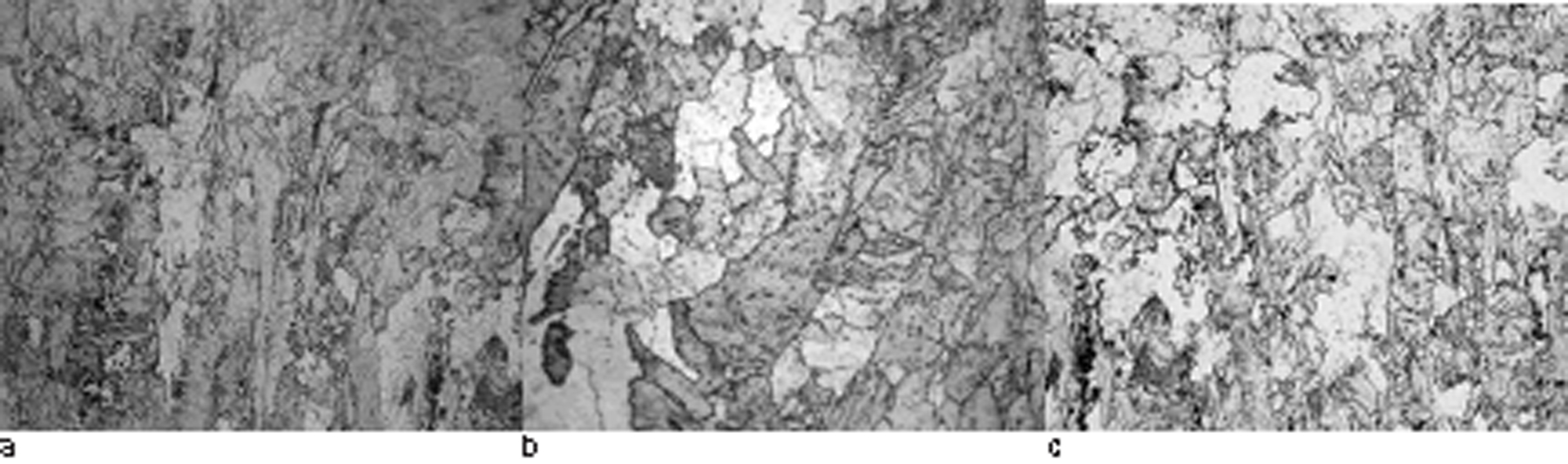
Microstructures (magnification: ×500) of a 7 kA, 12 cycles, weld metal, b 9 kA, 8 cycles, weld metal and c 9 kA, 8 cycles, HAZ
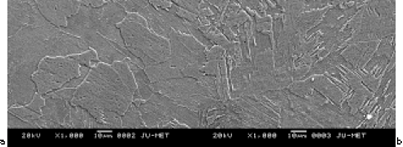
a weld metal; b HAZ
Microhardness survey of the spot weldments (Fig. 5) reveals maximum hardness at weld metal followed by HAZ, base metal. Again, irrespective of heat input, highest hardness is observed at the weld centre with decreasing hardness gradient towards the fusion boundary, whereas uniform hardness is observed at HAZ.
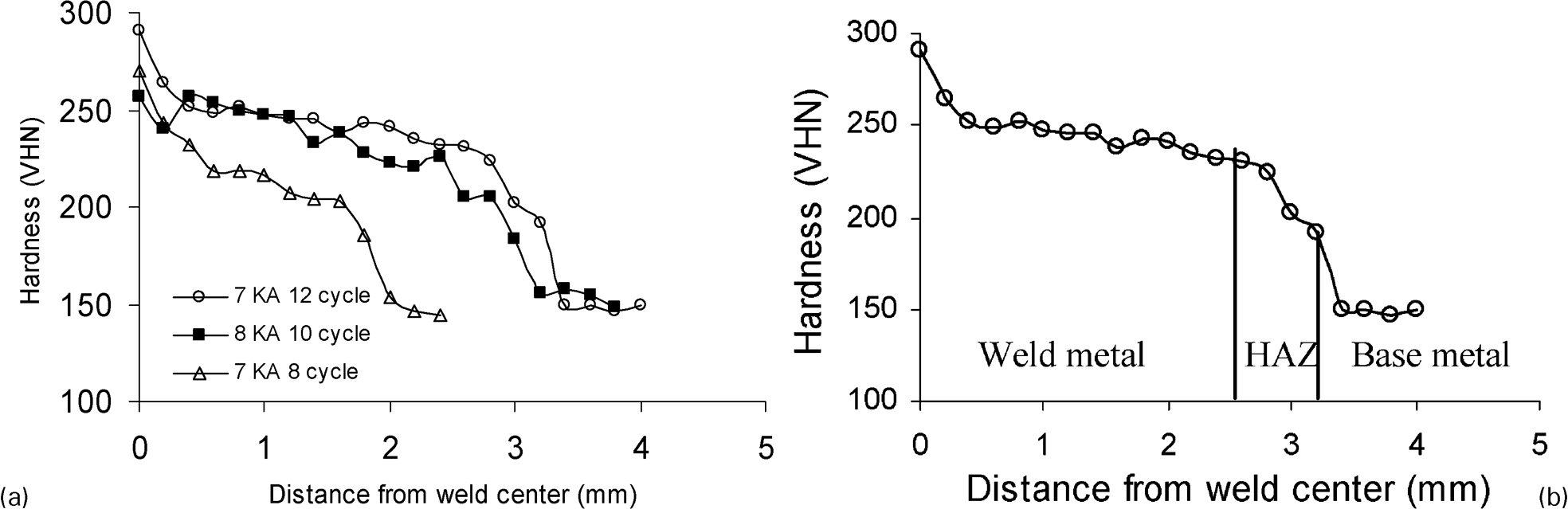
Microhardness survey a across weld nugget of different spot welded joints and b at 7 kA, 12 cycles, spot welded joint
Discussion
In the present study, all the spot welded joints selected from the weldability lobe (Fig. 1), conform to acceptability criteria based on tensile shear strength (Table 1). Improved shear tensile strength with increasing heat input is due to enhanced nugget size and nugget penetration, thereby leading to increased volume of weld metal. However, apart from strength, mode of fracture is also an essential acceptability criterion for spot welded joints and dimple fracture appearance (Fig. 2) indicate ductile failure mode for all the spot welded joints.
Microstructure of the above weld joints was analysed in detail under optical microscope, SEM and TEM. Microstructural studies of resistance spot welded joint, reveal ferritic structure at HAZ and weld location (Figs. 3 and 4), similar to that of base metal. This may be attributed to lower carbon and alloy content of base metal, which possibly has not responded to any phase transformation in the weld or HAZ in spite of very high cooling rate (∼104°C s−1) associated with resistance spot welding. The electrical resistance at sheet/sheet interface being highest, melting starts at the faying surface. Solidification of weld pool starts from two outer edges of the molten metal in contact with the water cooled electrodes, resulting in formation of columnar grains. The molten metal entrapped between two opposite layers of columnar grains i.e. at the faying surface, solidifies last developing fine equiaxed zone. The high degree of columnarity in weld metal despite rapid cooling rate is attributed to absence of the second phase. 11 Furthermore, enhanced degree of columnarity at weld with increasing heat input is probably due to increased superheat12,13 whereas grain coarsening at HAZ is associated with high temperature (∼775°C) experienced at HAZ. 14
It is quite surprising that despite any phase transformation in the weld and weld having mostly coarse columnar grain attributes very high hardness as compared to base metal, which show fine equiaxed grain. Similarly, HAZ with significant grain coarsening also shows higher hardness than base metal.
In search of the basis of hardness increment in weld metal as compared to base metal, TEM study of base metal and different welds was performed. A significantly higher degree of dislocations forming cell and subgrains is observed in weld metal than base metal (Fig. 6). The high dislocation density in weld metal is considered to be originated from rapid solidification of the weld pool under electrode pressure.
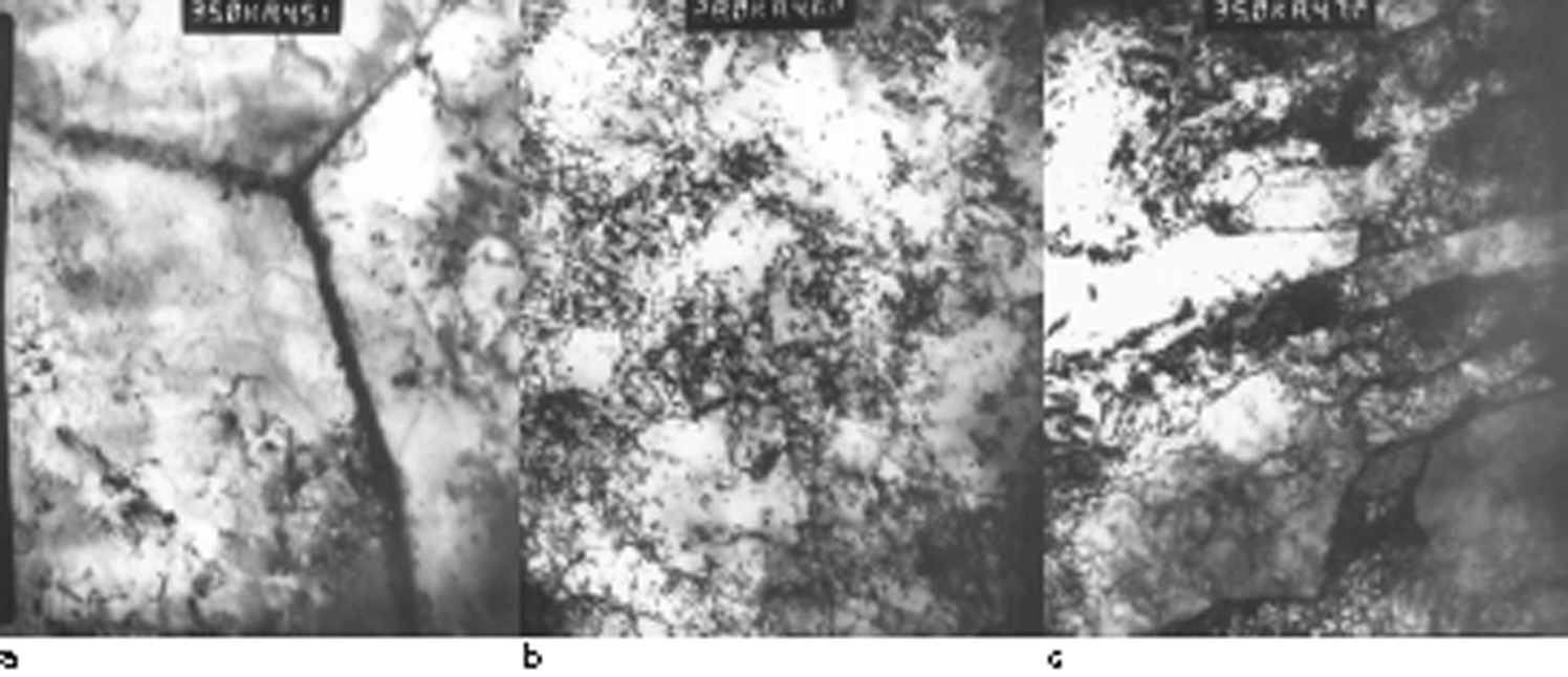
Images (TEM) of dislocation density at a base metal and weld metals under different spot welding conditions of b 7 kA, 12 cycles and c 9 kA, 8 cycles
In resistance spot welding, weld nugget develops from the molten weld pool by almost instantaneous solidification, under constant electrode pressure due to excessive faster cooling rate. Furthermore, under such solidification condition the weld nugget experiences deformation, which is clearly evident in the nugget penetration of weld metal (Table 1). The high dislocation density is probably a result of severe thermal stress and nugget deformation. On the other hand, thermal severity in HAZ being lesser than weld metal and HAZ being not in direct contact with the electrode, lesser thermal stress and deformation are expected in HAZ than the weld metal. Therefore, less extent of dislocation in HAZ is expected.
Intense local heating followed by rapid cooling in RSW is liable to cause temperature gradients across the weldments resulting in thermal stresses.6,14 During welding, temperature rise in the weld zone is much higher (∼2000°C) than the HAZ (∼775°C),6,14 which restricts the expansion of hot metal, resulting in compressive stresses in the weld zone. On subsequent cooling, weld metal exhibits shrinkage, which again is constrained by the surrounding. This leads to generation of tensile stresses in the weld metal. The magnitude of the resultant tensile stress is observed to be highest at the weld centre and gradually decreases towards the HAZ. 6 These thermal stresses are likely to cause heterogeneous deformation leading to generation of crystal defects in spot weldments. 6
Apart from higher dislocation density, a greater degree of precipitation in weld metal than base metal is also revealed from TEM images (Fig. 7). It is apparent that the interstitials (C, N) of the base metal, arrested by stoichiometric Ti, Nb, have precipitated in a finer scale in the weld metal. The initial dislocation density has a pronounced influence on precipitation characteristics. 15 It has been verified experimentally and through thermodynamic modelling by previous investigators 16 that energy barrier for carbide precipitation is greatly reduced by dislocations as compared to homogenous nucleation of precipitates. Hence, in ferritic steel, carbides of niobium and titanium preferentially precipitate on dislocations.15,17 Furthermore, heterogeneous precipitation on dislocations permits ‘short circuit diffusion’ 17 leading to faster precipitation kinetics and greatly retard the rate of precipitation coarsening. Again, depending upon ratio of matrix volume and dislocation; diffusion coefficient changes. 17 This leads to finer precipitation originated from a large number of nucleation site. The presence of large number of dislocations in the weld metal probably accounts for the higher degree of finer precipitations in weld metal.
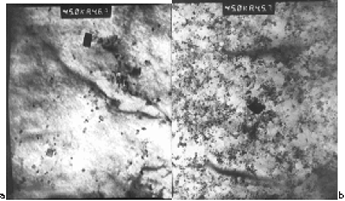
Images (TEM) of different precipitates present in a base metal and b 9 kA, 8 cycles, weld
It can be inferred that hardness increment in weld nugget is a manifestation of the resistance spot welding process, derived from the generation of high dislocation density and precipitate formation during spot welding. Heat affected zone being less severe with these metallurgical phenomena shows lower hardness than weld metal.
Conclusions
The following conclusions can be drawn from the present study.
Despite very high cooling rate, no phase transformation is observed in weld metal and HAZ of resistance spot welded IF steel.
Although grain size of weld metal and HAZ is sufficiently coarser than base metal, significant hardness increment at weld and marginal increase in hardness at HAZ as compared to base metal is observed.
Hardness increment in weld nugget is a manifestation of the resistance spot welding process derived from generation of high dislocation density and precipitate formation in IF steel.