
Abstract
The effect of primary α content on creep and creep crack growth behaviour of a near α-Ti alloy has been investigated at 600°C. The alloy was heat treated at different temperatures so as to obtain different volume fractions of equiaxed primary α in the range from 5 to 40%. Constant load creep tests were carried out at 600°C in the stress range 250–400 MPa until rupture of the specimens. Creep crack growth tests were carried out at 600°C and at an initial stress intensity level of 25 MPa m1/2. Creep data reveal that minimum creep rate increases and time to rupture decreases with increase in primary α content indicating that higher primary α leads to creep weakening. On similar lines, maximum creep crack growth resistance is associated with the alloy with lowest primary α content (i.e. 5%). Microstructural and fractographic examination has revealed that creep fracture occurs by nucleation, growth and coalescence of microvoids nucleated at primary α/transformed β (matrix) interfaces. On the other hand, creep crack growth occurs by surface cracks nucleated by fracture of primary α particles as well as by growth and coalescence of microvoids nucleated at primary α/transformed β (matrix) interfaces in the interior of the specimen ahead of the crack tip.
Introduction
The drive for higher efficiencies and reduced weight in gas turbine aero engines has led to the development of a number of near α-Ti alloys with improved temperature capability. The Timetal 834 is one of the latest near α-Ti alloys developed for compressor module of modern aircraft jet engines. High temperature creep is one of the prime requirements of Timetal 834 since the alloy is targeted for application up to ∼600°C. Several investigators1–3 have reported that the Ti alloys with fully transformed β structure exhibit superior creep and stress rupture properties as compared to bimodal microstructure consisting of primary α and transformed β. Furthermore, a recent study by the authors4 has revealed that the Timetal 834 alloy with fully transformed β structure also exhibits better creep crack growth (CCG) resistance. However, Ti alloys with fully transformed β structure is well known to exhibit inferior fatigue properties.2,5–7 In order to optimise both creep and fatigue properties of this material, several investigators varied the thermomechanical treatment to achieve a microstructure with well balanced mechanical properties for Timetal 834 alloy. The desirable microstructure of this alloy for compressor disc/blades application has been found to be ∼15% equiaxed primary α embedded in transformed β matrix. During thermomechanical processing of compressor disc/blades, there can be microstructural variation due to differential cooling rates as a result of variation in thickness from hub to web to rim region. Creep and fatigue properties of the alloy are influenced by a number of factors, such as phase morphology, size, presence of silicon as solid solution in the matrix or its precipitation as silicides and degree of aging.2,8,9 Any variation in primary α content resulting from differential cooling rate may influence the performance of the compressor significantly. In view of this, a detail study investigating the effect of primary α content on creep and CCG behaviour of a near α-Ti alloy conforming to Timetal 834 has been investigated, and results are reported in this paper.
Experimental
Material
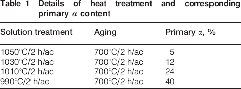
The Ti alloy used in the present investigation was produced by vacuum induction melting followed by vacuum arc remelting. The chemical composition of the alloy is 5·8Al–4·0Sn–3·5Zr–0·7Nb–0·5Mo–0·35Si–0·06C–0·07O (wt-%). The composition of the present alloy is very similar to that of the commercial near α-Ti alloy Timetal 834. The ingots were subsequently forged at 1100°C into 18 mm diameter rods. Specimen blanks for creep and CCG specimens were extracted from these rods. These blanks were heat treated at different temperatures as shown in Table 1 in order to vary the primary α content in the range 5–40 vol.-%. Subsequently, all the specimen blanks were aged at 700°C for 2 h and then air cooled.
Details of heat treatment and corresponding primary α content
Creep testing
For creep tests, cylindrical specimens having gauge length of 20 mm and gauge diameter of 4 mm were machined from the heat treated material. The apparatus and procedures used for creep testing and data analysis methods were followed according to ASTM E139-96 standard.10 Constant load creep tests were conducted in air at 600°C in the stress range of 250–400 MPa. Extensometer was mounted on the specimens and two linear variable differential transducers (LVDTs) were attached to the extensometer outside the heat zone, and the average of both transducers was used for plotting the creep curve. All creep tests were conducted until fracture. Creep crack growth tests were performed as per standard ASTM E-145711 where the compact tension type specimen geometry is recommended for CCG tests. Since the material used in the investigation was in 18 mm rod form, a single edge notch tension type specimen geometry having width of 15 mm, thickness of 2 mm and gauge length of 40 mm was adopted. A straight notch of 1 mm depth and 0·1 mm radius was cut in specimens using electrical discharge machining wire cut machine. Before testing, gauge portion of samples were polished metallographically, and marker lines were engraved at an interval of 0·5 mm to measure crack length optically during CCG testing. The specimens were precracked at a stress ratio of 0·1 at room temperature using a high frequency resonance fatigue testing machine. A constant load lever arm type CCG testing frame with a lever ratio of 1∶10 was used in the present investigation. The furnace has a quartz window on the front door for viewing the specimen and monitoring the crack growth optically during CCG studies. The crack growth was continuously recorded using alternating current potential drop technique. The load line displacement was measured using LVDT and extensometer assembly. Both the output values of alternating current potential drop and LVDT were continuously recorded during the test at a regular interval by a data acquisition system. Tests were continued until the fracture of specimens. A few tests were interrupted several times to measure crack length for calibration as well as to examine damage evolution ahead of the crack tip. All the tests were carried out at 600°C and initial stress intensity K level of 25 MPa m1/2.
Microstructural investigation
Detailed microscopic and fractographic investigations were conducted on crept specimens using optical and scanning electron microscopy (SEM) to understand creep fracture micromechanisms operative in this alloy under different test conditions. The fractured samples for optical and SEM examinations were first longitudinally midsectioned, mounted in bakelite and then polished following standard metallographic practice. The samples were then thoroughly cleaned in ultrasonic cleaning unit and finally with acetone. The cleaned samples were subsequently etched using Kroll's reagent for microstructural examination.
Results and discussion
Creep behaviour
Solution treatment at four different temperatures, namely 1050, 1030, 1010 and 990°C, has resulted in four distinct microstructures with varying primary α content as depicted in Fig. 1. The optical micrographs in Fig. 1 show bimodal microstructure with primary α content varying from 5 to 40%. The volume fraction of primary α is found to increase with a decrease in solution temperature from 1050 to 990°C. β grain boundaries are delineated by grain boundary α film. β grain size of the bimodal microstructure is finer than that of the fully transformed β size. Further β grain size is found to decrease with increasing volume fraction of primary α in the α+β heat treated microstructures.
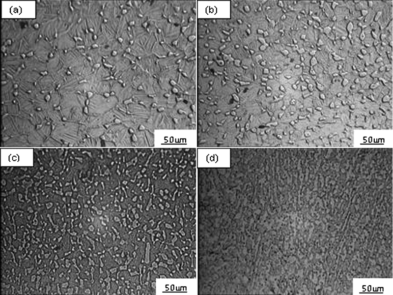
Optical micrographs showing variation in primary α volume fraction after solution treatment for 2 h at different temperatures
Typical creep curves of the alloy at a stress level of 300 MPa and at 600°C for different primary α contents are illustrated in Fig. 2. It is clear that creep strain accumulation with time becomes rapid as primary α content increases from 5 to 40%. Similar behaviour has also been observed for other stress levels. Variation of minimum creep rate (MCR) and time to rupture with primary α content, for different stress levels, is shown in Figs. 3 and 4 respectively. Creep data reveal that MCR increases and time to rupture decreases with increase in primary α content, thus indicating that higher primary α leads to creep weakening. Furthermore, it can be noted that the effect of percent primary α on MCR is more dominant at higher stress levels, whereas rupture life is more sensitive at lower stress levels. Creep weakening in alloys with bimodal microstructure has also been reported by several workers in a range of near α-Ti alloys.2,12–16 Different explanations have been proposed for the observed behaviour based on the alloy systems, microstructure and operative creep mechanisms, such as:
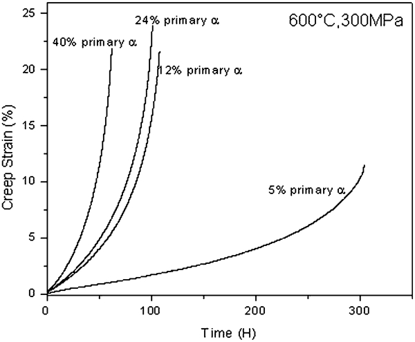
Creep curves as function of primary α at 600°C, 300 MPa
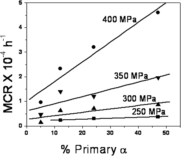
Primary α volume fraction versus MCR
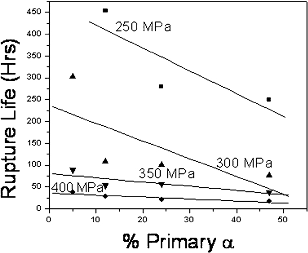
Primary α volume fraction versus rupture life
lower strength of lamellar matrix in the bimodal microstructure as a result of alloy element partitioning2
thin layer of β phase around equiaxed α that provides a high diffusivity path2
banding and texture of primary α leading to accelerated creep12,17
larger slip length of primary α as compared to that of α lath in transformed β18
grain boundary sliding being the dominant creep mechanism in the bimodal microstructure.13
Thus, operation of any or a combination of these mechanisms may lead to weakening of the alloy with increase in primary α content. Of these several mechanisms proposed, alloying elements partitioning in α phase appears to be more appropriate mechanisms for progressive creep weakening resulting from increase in primary α content. Partitioning of alloying elements in α phase reduces the strength of the lamellar matrix in bimodal microstructure in comparison to fully transformed β structure (i.e. fully lamellar structure). Thus, with increase in primary α content, the strength of the lamellar matrix in bimodal microstructure progressively decreases due to alloying element partitioning and accounts for the observed behaviour.
Creep crack growth behaviour
A recent study4 has revealed that a path independent energy line integral parameter like C* or Ct is a more appropriate crack tip parameter than the stress intensity parameter K for characterising CCG behaviour in Timetal 834 Ti alloy. This is because the stress intensity parameter K could not uniquely describe the crack growth rate data over the entire range, as it does not take transient effects in crack growth rate into account. In view of this, the CCG data analysis has been performed using C* as a crack tip parameter as defined in standard ASTM E-1457. The C* can be calculated from experimental data using the expression of the form

 the steady state load line displacement rate. The variation of crack length a and load line displacement Δ as a function of time at an initial stress intensity level K of 25 MPa m1/2 and 600°C for 5, 12 and 40% primary α content are shown in Figs. 5 and 6 respectively. As can be seen from Fig. 6, variation of load line displacement with time exhibits three well defined regimes similar to creep curves (Fig. 2), and the load line displacement rate becomes faster with increasing primary α content. Similarly, the alloy with highest primary α content exhibits fastest crack growth rate, and CCG rate decreases progressively with a decrease in primary α. Figure 7 shows variation of CCG rate da/dt with C* on log–log plot for different primary α content (i.e. 5, 12, 24 and 40%). The data for different primary α contents were fitted according to a power law equation of the form

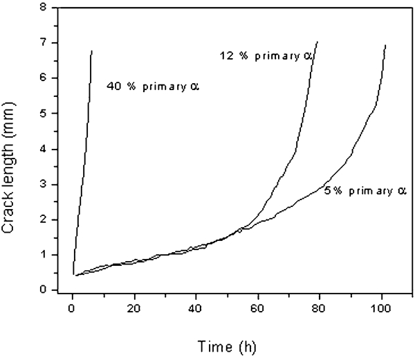
Crack length versus time
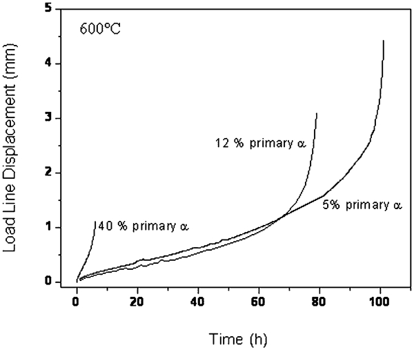
Load line displacement versus time
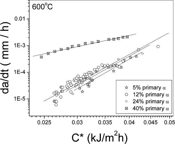
Creep crack growth rate (da/dt) versus energy integral parameter C*
Creep fracture and CCG micromechanisms
The microstructural aspects of creep fracture are illustrated in Fig. 8. It is evident from Fig 8 that creep fracture initiates in the interior in the form of cavities nucleated at primary α/transformed β interfaces. Subsequently, the growth and coalescence of microvoids lead to ductile dimple fracture as shown in Fig. 9. Detailed fractographic and microstructural examination of damage zone has revealed that the CCG in stable crack growth regime comprises two stages, namely, nucleation of microvoids/microcracks around crack tip and growth and coalescence of microvoids/microcracks, which subsequently join the main crack. Microcracks have been found to form by fracture of primary α particles at the specimen surface in bimodal microstructure Fig. 10. This may be due to the well documented fact that α phase has got more affinity as well as solid solubility for oxygen. The dissolution of oxygen in the α phase during CCG test makes the latter brittle; as a result, microcrack nucleation takes place during the creep deformation by fracture of primary α phase. A number of environment induced secondary cracks have formed at the specimen surface in the region all around the main crack tip and ahead of it as illustrated in Fig. 11. On the other hand, cavities or voids have formed at primary α/transformed β structure (i.e. matrix) interface in the interior and ahead of the crack tip, as also observed in case of smooth creep specimens with (α+β) microstructure (Fig. 8). The growth and interlinkage of both environment induced surface microcracks and interior microvoids is controlled by creep deformation of the surrounding matrix region ahead of the crack tip and eventually leads to CCG and final fracture of the specimen. The fractographic features near specimen surface and interior are shown in Fig. 12. Fractographs reveal flat brittle fracture features near specimen surface (Fig. 12a), while they reveal ductile dimples in the interior of the specimen (Fig. 12b).
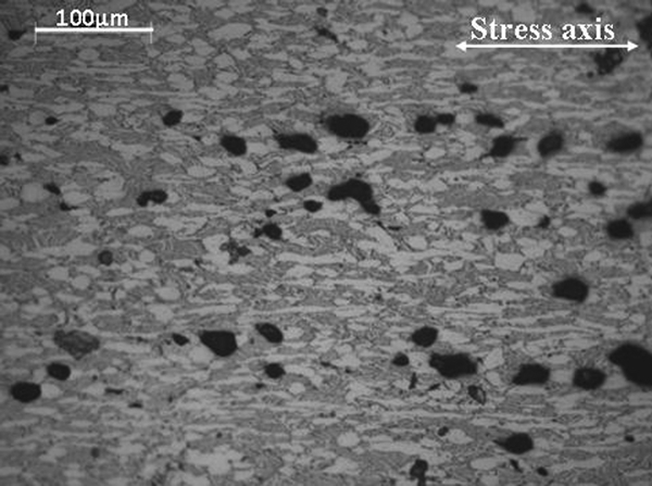
Formation and linkage of microvoids at primary α/transformed β interfaces
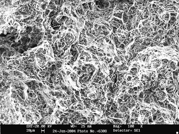
Fractograph showing dimple fracture
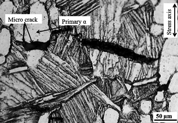
Formation and linkage of microcracks at primary α particles
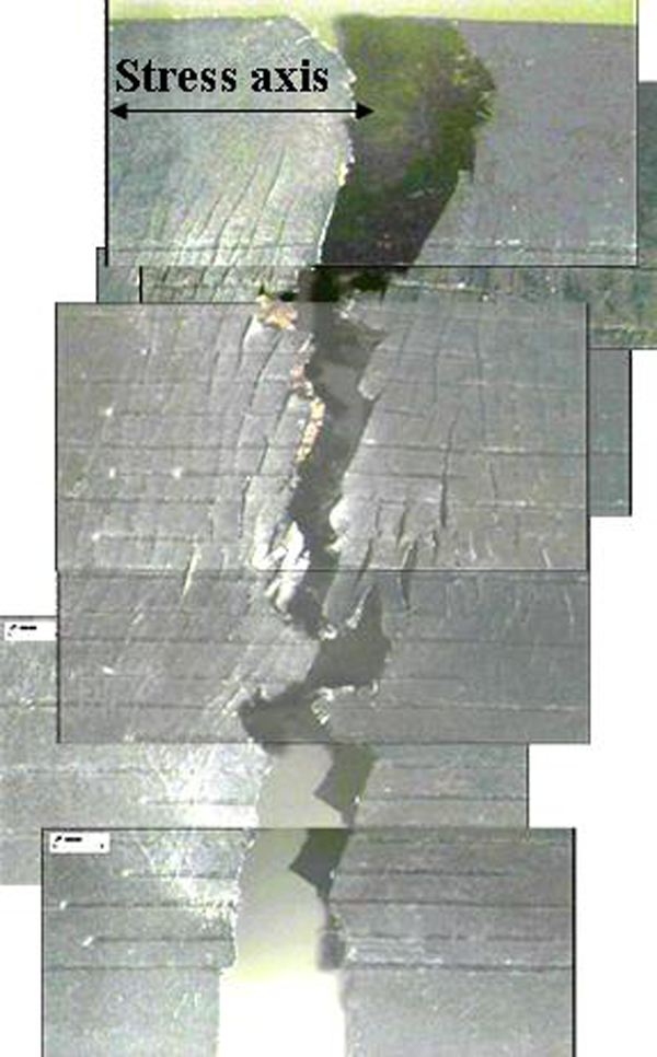
Series of optical micrographs showing damage zone around main crack of CCG specimen
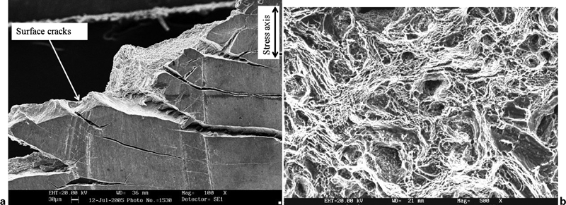
a flat brittle fracture near specimen surface and b dimple fracture in interior of specimen
Conclusions
Solution treatment at different temperatures has resulted in distinct microstructures with varying equiaxed primary α content in the range 5–40%.
Increase in primary α content leads to progressive increase in MCR and decrease in time to rupture, indicating that higher primary α content causes creep weakening.
Increasing primary α content also results in progressive lowering of CCG resistance of the alloy.
Creep fracture initiates in the form of cavities at primary α/transformed β (matrix) interfaces. On the other hand, CCG occurs by surface cracks nucleated by fracture of primary α particles as well as by growth and coalescence of microvoids nucleated at primary α/transformed β (matrix) interfaces in the interior of the specimen.
Footnotes
Acknowledgements
The authors are grateful to the DRDO for the financial assistance received. Creep and CCG testing by Mr B. Narsingh Rao is gratefully acknowledged. Thanks are due to the Director, DMRL for constant encouragement and for permission to publish this work.