
Abstract
Machined titanium components, such as medical prosthesis, require the greatest reliability, which is determined by process induced surface integrity. However, surface integrity of milled titanium components easily deteriorates due to the poor machinability of titanium alloys and cyclic chip loading during milling. Milling induced surface integrity, including anisotropic surface roughness, residual stress, surface microstructure alterations and microhardness, has received little attention. In the present study, a series of end milling experiments were conducted to comprehensively characterise surface integrity at various milling conditions of titanium alloy Ti–6Al–4V with TiAlN coated carbide cutting tools. The experiments were carried out under dry cutting conditions. For a range of cutting speeds, feeds and depths of cut, analyses of machined surface roughness, residual stress, microhardness and the microstructural observations were carried out. The present work aims to evaluate the influence of different milling conditions on workpiece surface integrity.
Introduction
Titanium alloys have been widely used in the biomedical, aerospace, petroleum and automotive industries because of their elevated mechanical resistance having a low density and their excellent corrosion resistance, even at high temperatures.1,2 Despite these features, it is very difficult to machine titanium alloys due to their poor machinability that intimately led to their thermal and chemical properties. 3 In fact, the high chemical reactivity of titanium, which increases with high temperature, produces an early damage to the cutting tools, affecting the final quality of obtained surface and increasing the production costs. 4
Ti–6Al–4V is the most commonly used alloy; it is an extensively employed material for medicine, aerospace and other components that operate at high temperatures and in corrosive as well as hostile environments, such as aerospace and missile parts, gas turbine engines, steam turbines and chemical and petrochemical equipment. 5 In all these applications, resistance to fatigue, creep, corrosion and distortion depends on the characteristics of the machined surfaces. Titanium alloys are generally used for a component that requires the greatest reliability, and therefore, the surface integrity must be maintained. Hence, to machine any component, it is essential to satisfy surface integrity requirements. 6
Surface integrity is a measure of the quality of a machined surface and is interpreted as an element that describes the actual structure of both surface and subsurface. 1 It is very interesting to study the effects of cutting conditions on residual stresses, surface roughness and microhardness for a defined tool/workpiece material type. Accordingly, it is very clear that information concerning surface integrity (surface quality, surface microhardness and residual stresses) of the machined surface region will be very valuable in the design and manufacture of parts.4,6 Efforts have been made by several researchers in the past few decades to study the relationships between the machining process conditions, the nature of the surface alterations produced and their effect on the product's functional performance. In fact, Koster and Field 7 found that a wide range of fatigue strengths could be achieved in titanium alloy Ti–6Al–4V, as a result of different machining processes. They claimed that these variations occurred because of alterations in integrity induced in the material surface as a result of the machining operation. More recently, Sasahara et al. 8 have shown that there is a strong connection between the surface integrity induced by machining and the resulting fatigue life of the product.
The aim of the present research was to determine the possible effects of high speed milling process on the Ti–6Al–4V surface integrity by conducting surface and microstructural analyses of the workpieces machined with high speed parameters using TiAlN coated carbide tool. This includes surface topography study, residual stress and hardness measurements and also metallographic analysis of the specimens using an optical microscope in order to analyse the microstructural deformations, which might be formed as a result of high speed machining processes. As well known, Residual stresses in machining are produced as a consequence of inhomogeneous plastic deformation induced by mechanical and thermal loadings associated with the chip formation process and the interaction between the tool and the freshly machined surface in the vicinity of the tool nose. In other words, residual stress is one of the most relevant practical parameters used for evaluating the quality of the machined surface, particularly when critical structural components are produced, with the objective of reaching higher reliability levels.6–8
Prostheses design and manufacturing
The design and manufacturing of the medical prostheses require a multistep design and manufacturing process. It is common in the first step, after identification using computer tomography, to process the medical image, with high resolution and precision in the reconstructed contours, and enter it into a computer aided design system. In the second step, after the creation of a three-dimensional (3D) geometric model of the implant, prosthesis is designed. In the third step, the construction is subjected to strength examination for optimum performance, loads are applied to the implant and the materials’ strength is calculated. The fourth step involves verification of the prosthesis construction through consultation between the designer and orthopaedic surgeon, taking into account the surgeon's preferences as to, for example, the method of implantation, the coating of the prosthesis, etc. The fifth and final step is the manufacturing of the prosthesis, which is a very difficult job to perform due to the uneven curvatures and complex shapes of the parts. 9 Computer numerically controlled (CNC) machine tools are needed to machine such a component, according to an elaborated program. Such parts as femoral condyle with intricate shapes and varying curvatures are very difficult to manufacture by machining. A five-axis CNC machine is needed to machine such a component (see Fig. 1). 10 Since the hip prosthesis femoral head is spherical, it is manufactured in precision turning using a CNC lathe.
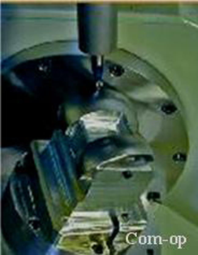
Milling operation of knee prosthesis on CNC five-axis machine tool
Titanium alloy applications in medicine
Materials used for biomedical applications cover a wide spectrum and must exhibit specific properties. The most important property of biomaterials used for manufacturing implants is their higher biocompatibility and corrosion resistance against body fluids. Among them, titanium and titanium based alloys are the most frequently used in biomedical applications. 10
Ti–6Al–4V has long been a main medical titanium alloy. It may be considered in any biomedical application, particularly for implantable components, because of its biocompatibility, good fatigue strength and low modulus. It could also be considered for any application where a combination of high strength, light weight, good corrosion resistance and high toughness is required, especially at cryogenic temperatures. Typical uses include joint replacements, bone fixation devices, surgical clips and cryogenic vessels. 9
Experimental conditions
The details of experimental conditions, instrumentations and measurements and the procedure adopted for the study are described in this section.
Workpiece materials
The workpiece materials used in all the experiments were taken from a bar of an α–β titanium alloy Ti–6Al–4V. The chemical composition of the Ti–6Al–4V alloy is Ti–6Al–4V–0·3Fe–0·08C–0·05N–0·01H–0·2O (wt-). Figure 2 shows the results of energy dispersive spectroscopy analysis of workpiece material Ti–6Al–4V. The workpiece had a microstructure, which consisted of an elongated α phase surrounded by fine, dark etching of β matrix (see Fig. 3). Titanium alloy Ti–6Al–4V is an extensively used titanium alloy and presents high strength, depth hardenability and elevated temperature properties up to 400°C (see Table 1). The crystallographic texture has been weakened, thanks to the special treatment carried out by the materials supplier (Aeronautical Department, Safran group, Paris, France).
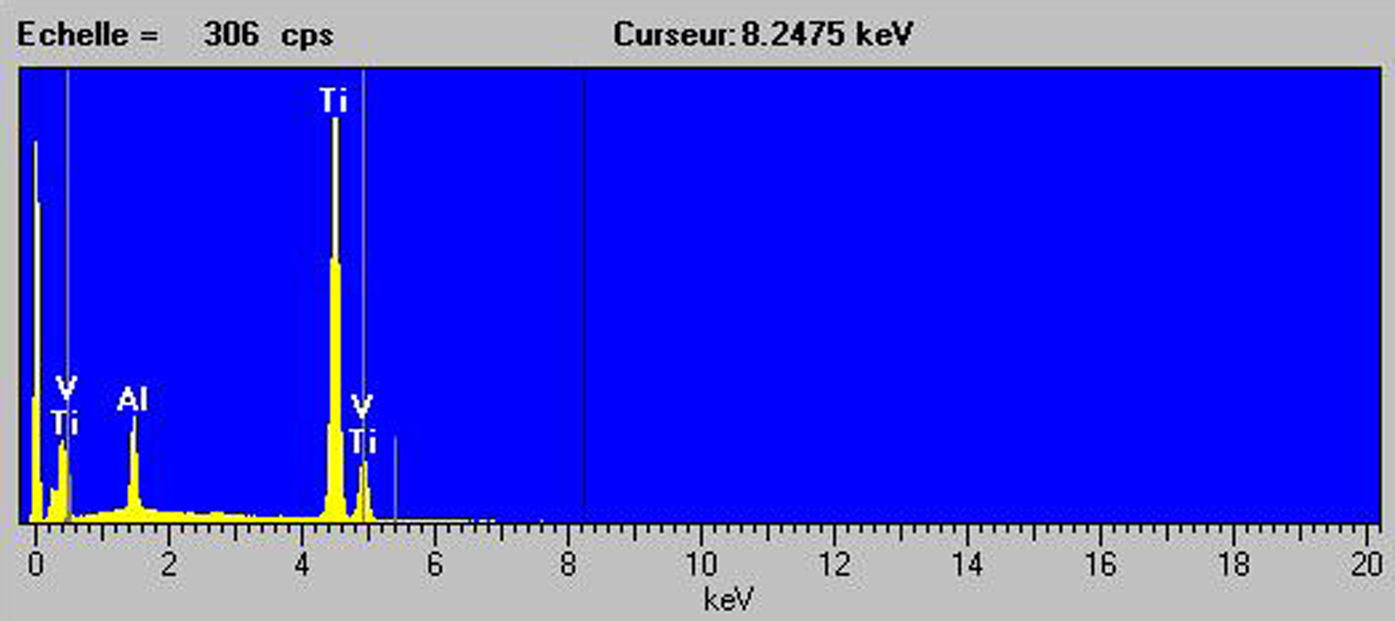
Energy dispersive spectroscopy analysis of workpiece material Ti–6Al–4V
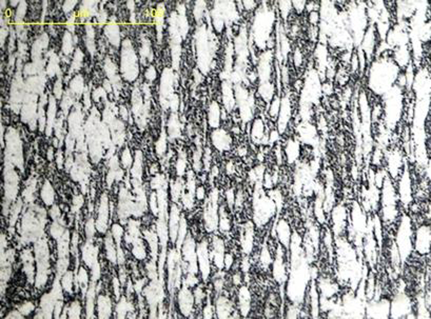
Initial microstructure of workpiece material Ti–6Al–4V
Mechanical properties of Ti–6Al–4V alloy at room temperature

Cutting tool materials
The test conditions used in the experimental part are selected as the common conditions in high speed machining. A number of cutting experiments were carried out, in dry cutting conditions, on a five-axis vertical milling machine Deckel Maho DMU 50 (Deckel Maho Pfronten GmbH, Pfronten, Germany) evolution equipped with a maximum spindle speed of 18 000 rev min−1 and Siemens control 840D (Siemens, Erlangen, Germany) (Ref. 5) (see Fig. 4). Cemented tungsten carbide coated inserts were used for the milling tests. The inserts and the tool holder were manufactured by Sandvik, and their references were R216F-16 40 E-L P20A and R216F-16A16S-063 respectively. The cutting tool was observed using a microscope after each trial, in order to ensure that tool wear does not affect surface roughness.
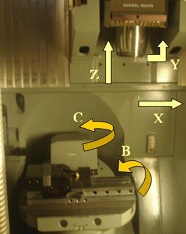
Five-axis milling machine
Machining tests and operating parameters
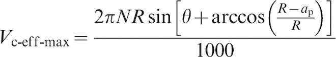
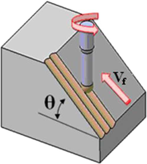
Cutting parameters held constant were as follows: axial depth of cut ap = 0·4 mm, radial depth of cut ae = 0·5 mm, feedrate Vf = 900 mm min−1 and revolution speed N = 3000 rev min−1; dry cutting; cutting method, up milling; and cutting direction (when operating at inclined milling), vertical upwards, as it appears in Fig. 5. To study the influence of the cutting speed on the surface integrity, the workpiece inclination angle, which is in direct relation with the cutting speed (see equation (1)), was varied
Experimental configuration of cutting test
Surface finish and surface integrity
The generated machined surface was measured using a 3D measurement station STIL Micromeasure 2, which is optimised for roughness measurement, and a 3D microtopography, in the feed and pick feed directions. Sectioning of the machined specimens was carried out under very strict conditions. All of the specimens used for microstructural analysis have been mounted and polished up to 0·1 μm. Kroll's reagent has been used for etching of the specimens. The microstructure analysis of the specimens was then conducted under optical microscope, and the pictures were taken on the machined surfaces to record possible metallurgical alterations beneath the machined surfaces. In addition, special attention was given to a disturbed or plastically deformed layer that was formed immediately under the machined surface.
The same metallographic specimens have been used for microhardness measurements using a Vickers microhardness tester with a load of 200 g for waiting time of 10 s.
The residual stresses in the machined surfaces and in the subsurfaces were analysed by the X-ray diffraction technique using the sin2ψ method. These results have been compared with those of two angle technique; both techniques are also widely used in manufacturing engineering by machining. In both of these techniques, the associated stress error was <45 MPa.
To obtain the residual stress distribution in the affected layer, the surface was attacked by electropolishing with a solution of phosphoric and sulphuric acid. In fact, measuring residual stress distributions as functions of depth into the sample surface requires electropolishing layers of material to expose the subsurface layers. Electropolishing is preferred for layer removal because no residual stresses are provoked, and by performing it properly, there is no preferential etching of any of the grain boundaries.11,12 Any mechanical method of removal, regardless of how fine the abrasive or machining method, deforms the surface and induces residual stresses, altering severely the state of stress present in the sample. Such methods must be avoided. Thick layers can be removed using a combined machining or grinding procedure, followed by electropolishing to remove 0·2 mm of material to eliminate the machining or grinding residual stresses. The crystallographic texture is not so high, as confirmed by the materials supplier and also by the residual stress measurement laboratory (MELIAD-FRANCE research laboratory, Toulouse Cedex, France, certified by official state standard organisation Association française de Normalisation).
Results and discussion
The results are presented in three different sections. First, the surface roughness measurements are shown. Second, the evaluation of the residual stresses is presented. Third, the microstructure and microhardness analyses are presented. Combined, they provide a complete picture of the surface integrity of the machined workpieces.
Surface roughness
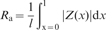
There are many parameters used in the literature and industry related to surface roughness. Among the two-dimensional (2D) surface roughness parameters, the most popular is average roughness. It is quoted as Ra (see equation (2)). Mathematically, Ra is the arithmetic value of the departure of the profile from centreline along sampling length13–16
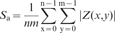
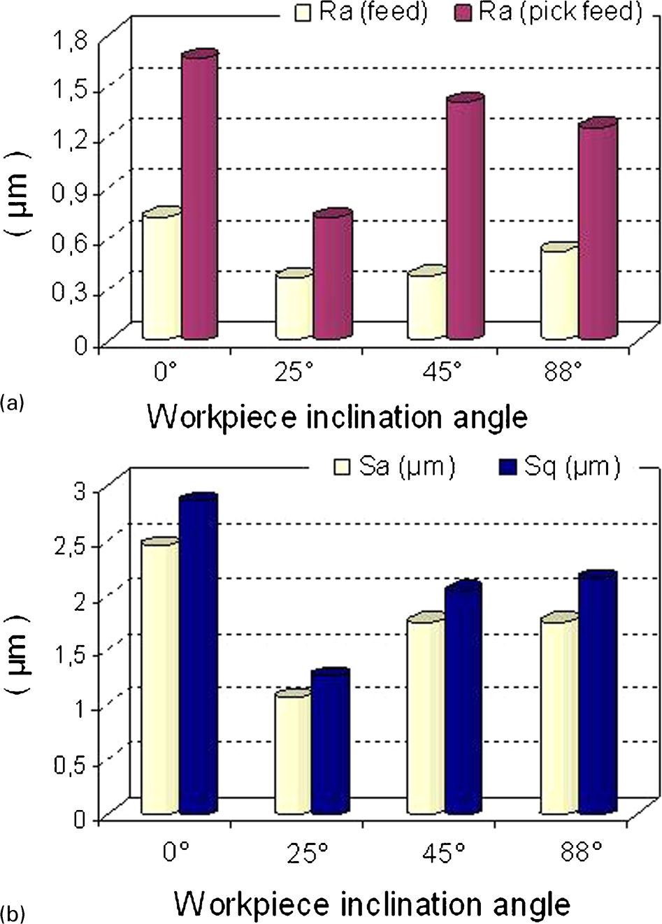
a 2D parameter: Ra (in feed and pick feed directions); b 3D parameters: Sa and Sq
The ratio of maximum/minimum for the measures taken along the pick feed direction is considerably larger than that obtained for the measures taken along the feed direction, implying that the effect of cusp height, in deteriorating the surface quality, is more pronounced in pick feed direction than in the feed direction.
Figure 7 shows the 2D surface maps and traces of the profiles of finished surface produced at a depth of cut of 0·4 mm and different workpiece inclination angles. The analysis of the results shows the improvement of the machined surface texture quality when it is machined with a workpiece inclination angle of 25°. It is visibly found that the surface of the first trial, when machining without inclination of workpiece, i.e. θ = 0° (in the case of three-axis machining), reveals a bad microgeometrical quality as shown in Fig. 7a and has a much higher variation between the maximum peak to valley height values and surface roughness total profile (Pt = 10·6 μm) compared to θ = 45° (Pt = 7·49 μm), θ = 88° (Pt = 10 μm) and θ = 25° (Pt = 5·12 μm), which has the best results. The high values of the surface roughness for the inclination angles 88° can be explained by the presence of the tool deflection phenomenon, which occurs during machining.
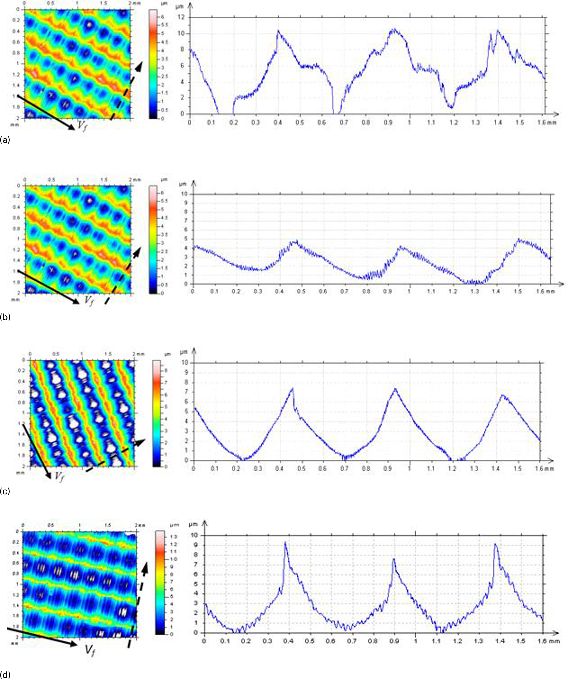
a θ0°; b θ25°; c θ45°; d θ88°
In ball end milling of complex shapes, the cutting speed varies according to the contact position of the cutting edge in relation to the workpiece (see equation (1)). The cutting speed of the cutting edge centre is almost zero. Therefore, when the cutting tool axis is normal to the cutting plane, the machined surface produced can be rough, and tool chipping or wear can be severe due to the near zero cutting speed. In this case, adjusting the machining inclination angle between the cutting tool and the workpiece can improve tool performance and surface roughness.
Residual stress
As well known, the measurement of the residual stresses as a function of the depth gives major information about the real stress levels created in the materials. The residual stress distributions produced by machining are not quite uniform, and they can induce residual stress fields that differ in magnitude and sign with direction in the plane of the surface. For this reason, the principal residual stresses should be measured as a function of depth (through the thickness by electropolishing layer removal technique). After that, the residual stress in any direction can be predicted from the principal stresses with their orientation relative to the sample geometry.
Figure 8a shows the results of residual stress measured for the four workpiece inclination angles experimented. From the figures, the residual stress shows different depth profiles for different workpiece inclination angles. In all specimens, the compressive stresses increased below the surface. Maximum compressive stress found was 10–20 μm below the surface. The concentration of the specimens had a maximum value ∼10 μm. The maximum value differed from −398 MPa on the specimen with an inclination angle of 45° to −528 MPa when machining without inclination angle. At a depth of 100 μm, all specimens showed compressive stresses of less than −200 MPa. The residual stress at the machined surface and the maximum residual compressive stress induced beneath the machined surface differed greatly. Stresses were highly compressive, up to 500 MPa, which can be explained by the likely overriding mechanical rather than thermal effect. The four plots follow the same tendency of decreasing compressive stress with increasing depth beneath the machined surface. It can be seen that increasing the workpiece angle, which induce the increase in effective cutting speed,5,16 caused the mean level of compressive stress to decrease; same results were found for the highest residual stress value (see Fig. 8b). This is probably due to the absence of the rubbing effect, which occurs at the centre of the ball nose end mill and tends to induce compressive residual stresses.
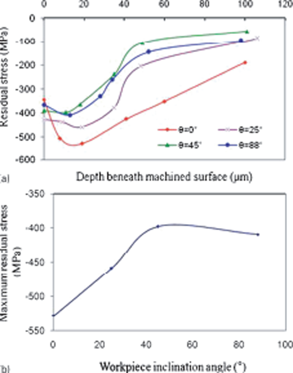
a residual stress profiles; b effect of inclination angle on maximum residual stresses
Results presented in the present study are valuable since they show that compressive residual stress can be generated when inclined end milling of the titanium alloy Ti–6Al–4V. Indeed, the amount of compressive stresses generated can be altered depending on the workpiece inclination angle, the cutting speed and the axial depth of cut. It is also clear that by selecting specific machining conditions, a surface free of residual stress can be obtained even if a considerably high speed is used; results were confirmed by Jacobson et al. 20 and El-Wardany et al.21,22
When residual stress is generated, there is an effect from both the heat generated and mechanical work going into the surface and subsurface. When increasing cutting speed, the strain rate is also increased in the process, which gives more mechanical work to the process, leading to compressive stress. 23 Eliminating or minimising the residual stresses in the surface layers of a machined component can improve the static and dynamic strength, as well as the physical properties of the surface.
Microhardness, microstructure and metallurgical alteration
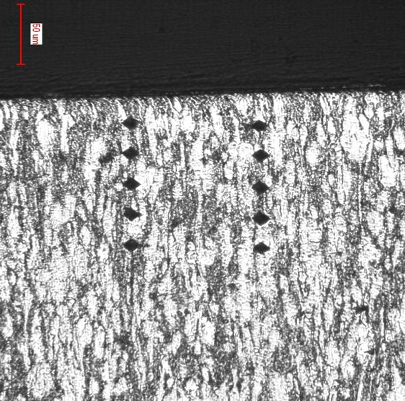
In the case of the hardness measurement, the hardness profile has been evaluated on the surface as a function of the distance from the machined surface. These values show generally the surface properties, the level of the work hardening of the deformed layer produced at the local surface. The results of the hardness measurements are sometimes sensitive to the local microstructure that may be different. The hardness measurements are the mean values of the two profiles taken from the surface of the specimen, as will be seen in the figure of the microhardness measurement prints (Fig. 9).
Microhardness measurement prints
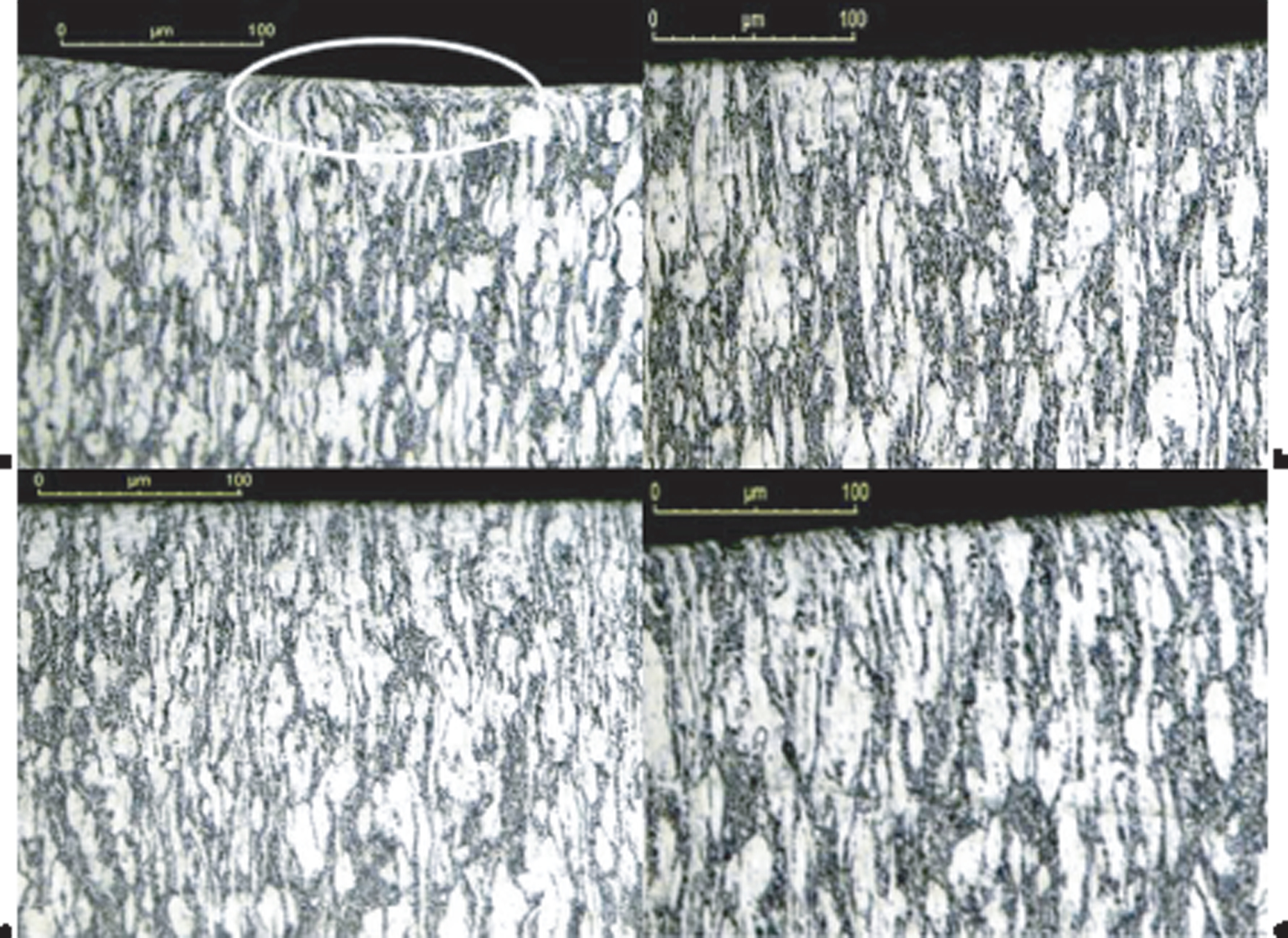
Microstructures of the machined surface produced when machining under dry cutting conditions are shown in Fig. 10. It was found that when machining under dry conditions, a thin layer of disturbed or plastically deformed layer was formed immediately beneath the machined surface General microstructures of the machined specimens show more or less this type of deformed layer just under the machined surface. In few of the specimens, however, at the end of cutting strict plastic flow, tearing and deformation of the microstructure are detected. This caused the formation of a very thin white layer of hardened material on top of the machined surface.
a θ0°; b θ25°; c θ45°; d θ88°
Figure 10a shows a micrograph of the surface in the pick feed direction, which clearly illustrates a deformed layer just under the machined surface. These types of defects are usually reported during the machining of titanium alloys.11,24–28 Contrary to these deformed layer observations, any deformed layer or disturbed microstructure are observed for the second configuration when θ = 25° (see Fig. 10b).
Measurements of the microhardness profiles have been carried out up to 130 μm beneath the machined surface, and the mean values for each depth were recorded and plotted. Figure 9 presents the measurement prints of the microhardness tests. The profiles of microhardness as a function of the distance from the machined surface are illustrated for all machined surface specimens produced when machining without or with workpiece inclination angles (Fig. 11). In fact, this figure shows clearly that the maximum value of hardness was intense in the range of 0–50 μm beneath the surface for all the trials (due to the workhardening effect). The high surface hardness values recorded was due probably to a bigger contact area between the cutting tool and the workpiece material. The top layer of the machined surface practised workhardening process; hence, the hardness measurements are higher than the average hardness of the workpiece materials. However, any softening effect (overaging of the materials) was observed in the material beneath the top layer. Confirming the results of the present paper, Che-Haron and Jawaid 25 and Ezugwu and Wang 28 claimed that a bigger contact area between the cutting tool and the workpiece would increase the heat generated when machining titanium alloy under dry machining. Under the experimental conditions applied in the present paper, the major part of the changes in the microhardness was concentrated up to 140 μm beneath the surface.
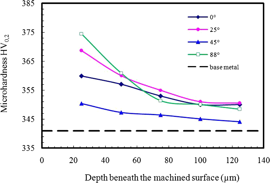
Microhardness distribution and variation in subsurface
Summary
The present paper discusses the influence of the machining conditions, namely, the workpiece inclination angle and the cutting speed, on the surface integrity of the titanium alloy Ti–6Al–4V generated in high speed end milling. From this study, the following results can be drawn.
Workpiece inclination angle proved to be an influential parameter for surface roughness. In this study, θ = 25° provided the best surface finish because of avoidance of cutting at the tool's centre (when θ = 0°) and tool deflection phenomena, which is important at θ = 45° and θ = 88°.
Machined surface generated when inclined milling Ti–6Al–4V with TiAlN coated carbide tool is generally acceptable and free from physical damage such cracks and tears. A detailed investigation beneath the machined surface proves that damage due to the workpiece inclination angle appears to be in the top layer of the machined surface, and the thickness of this layer is very low. Furthermore, it shows, in some cases, subsurface alteration such as plastically deformed layer.
Machining without workpiece inclination angles produced a thin layer of disturbed or plastically deformed layer formed immediately beneath the machined surface on the machined surface. This did not appear at θ = 25°. Besides, none of the machined surface specimens show the appearance of heat affected zones or white interface layer on top of the machined surface.
At higher workpiece angle, the mean compressive stress decreased slightly due to the absence of the rubbing effect, which occurs at the centre of the ball nose and mill and tends to induce compressive residual stresses.
The cuttings conditions obviously influence the microhardness of the machined surface.
Footnotes
Acknowledgements
The authors acknowledge Professor Jean Marc Linares and the members of laboratory ISM UMR6233 in the IUT of Aix en Provence, France, for their contribution to the present study. They equally appreciate the help of Professor Abdelwaheb Dogui and their colleagues at LGM Laboratory in ENIM, Tunis, Tunisia.