
Abstract
The tensile properties of aluminium alloy 7010 plates, heat treated to varying aging conditions, i.e. naturally aged, underaged, peak aged and overaged, were examined at ambient and subzero (−50°C) temperatures. It is shown that the maximum increase in strength properties (both 0·2 proof stress and ultimate tensile strength) upon changing the test temperature from ambient to subzero (i.e. −50°C) is obtained in the case of the naturally aged samples, while there is a minimal increase in the strength properties of the underaged samples when tested at −50°C. These results are discussed in light of changes in the workhardening behaviour of the materials with aging.
Keywords
Introduction
The tensile properties of peak aged and overaged 7xxx series Al–Zn–Mg–Cu alloys tested at ambient and subzero temperatures are reported in the literature.1 The data show improvements in the tensile strength properties of the materials when tested at subzero temperatures. Such strength increments are usually attributed to the increased rate of workhardening due in turn to the increased values of shear modulus of the materials at reduced temperatures. However, there has so far been no report in the literature that took the microstructure of the materials into consideration while discussing its strength properties obtained at subzero temperatures. It is the purpose of the present communication, using aluminium alloy 7010 plates heat treated to varying aging conditions, to establish that the microstructural factors controlling the workhardening ability of the material directly influence the subzero temperature tensile strength properties.
Experimental
The chemical composition of aluminium alloy AA 7010 examined in the present work is Al–6·3Zn–2·3Mg–1·5Cu–0·14Zr–0·04Fe–0·02Si (wt-). Fe and Si, associated with the primary Al, are present as impurities in the alloy. The alloy was prepared in an induction furnace, cast, homogenised and scalped. The resultant slabs (335×300×100 mm) were soaked at 435°C for 4 h followed by rolling to produce plates of 15 mm thickness using optimum rolling speed, intermediate annealing and cross-rolling parameters.
The 15 mm thick plates were solutionised at 465°C for 1·5 h, quenched in water at ambient temperature and subjected to different aging treatments as follows: 2 months at ambient temperature (naturally aged), 8 h at 100°C (underaged), 24 h at 120°C (peak aged) and 8 h at 100°C+8 h at 120°C+8 h at 170°C (overaged).
Round tensile specimens were machined from the heat treated plates. Owing to the use of cross-rolling, the variation in tensile properties between the longitudinal (tensile axis being parallel to the rolling direction) and long transverse directions was considerably minimised. In this article, the tensile properties obtained in the long transverse direction are only reported. Tensile tests were carried out using 25 mm gauge length specimens that were pulled in tension at a nominal (initial) strain rate of 3×10⁻⁴ s−1. Tensile tests were carried out at ambient temperature and at −50°C until fracture.
A combination of light microscopy (to examine the grain structure), transmission electron microscopy (to examine the morphology of subgrains developed during hot rolling and subsequent solution heat treatment and the formation of precipitates within the grain and at the grain boundary during aging) and scanning electron microscopy (to examine the fracture surfaces of failed tensile samples) was utilised in the present investigation. Keller's reagent was utilised as an etchant to reveal the grain structure on the polished surfaces of the heat treated plates. Thin foils for TEM were prepared, using discs of 3 mm in diameter, which were spark cut from mechanically ground strips of 0·2 mm thickness. Specimens for TEM were prepared by electrolytic polishing using 30 nitric acid at −35°C. TEM was carried out on a FEI Technai 20 TEM operating at 200 kV. SEM was carried out on a LEO 440I scanning electron microscope operating at 20 kV.
Results and discussion
Figure 1a represents a triplanar composite micrograph, imaged by optical microscopy, showing the grain structure developed in the 15 mm thick, peak aged plates. The surface of the plates is largely recrystallised, while the planes normal to the surface comprise of elongated grains that are partially recrystallised. Figure 1b represents a transmission electron micrograph (in <011>Al projection) showing the presence of subgrain structure in the majority of unrecrystallised regions of the material.
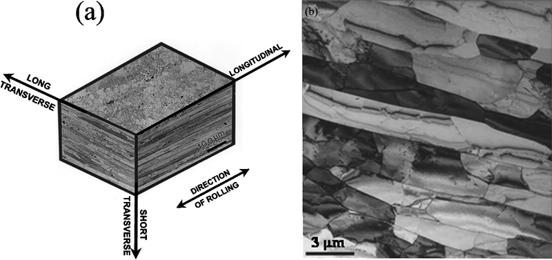
a triplanar composite micrograph, imaged by optical microscopy, showing partially recrystallised grain structure and b transmission electron micrograph showing subgrain structure, in 15 mm thick, AA 7010 peak aged plates
Table 1 shows the tensile properties of naturally aged and artificially aged plates tested at ambient temperature and at −50°C. The major features of the tensile properties are as follows:
Tensile properties of naturally aged and artificially aged, 15 mm thick, AA 7010 plates tested at ambient temperature and at −50°C*
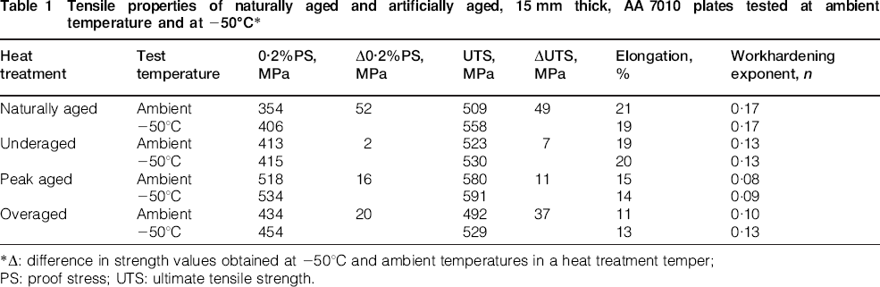
*Δ: difference in strength values obtained at −50°C and ambient temperatures in a heat treatment temper;PS: proof stress; UTS: ultimate tensile strength.
the increase in tensile strength properties [both 0·2 proof stress (PS) and ultimate tensile strength (UTS)] upon changing the test temperature from ambient to −50°C increases in the following order of heat treatment: underaged, peak aged, overaged and naturally aged, i.e. the strength increment is the highest for the naturally aged material, and it is the least for the underaged material
the workhardening exponent n continuously decreases from naturally aged to peak aged condition following which it shows an increase
there is a decreasing trend in the percentage elongation from naturally aged to overaged condition.
However, another major but a known trend of the tensile properties shown in Table 1 is that there is an increase in 0·2PS up to the peak aged condition, i.e. at the precipitate cutting–bowing (by dislocations) transition, where the maximum strength is obtained. Following this, the strength properties decrease with overaging, where the strengthening mechanism is dictated by dislocations bowing between the non-shearable precipitates. Figure 2 represent transmission electron micrographs (in two-beam gıīı, orientation near <011>Al projections) from naturally aged, underaged and overaged samples respectively, showing the following trends in the deformation behaviour. Strain localisation is not totally absent, but occasional and less prominent in the naturally aged samples; strain localisation is pronounced in the underaged samples, while the deformation is homogeneous in the overaged samples.
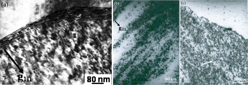
Transmission electron micrographs in two-beam orientation gīıī showing a less pronounced strain localisation in naturally aged sample, b intense planar slip/strain localisation in the underaged sample and c homogeneous deformation in the overaged sample respectively: Two-beam orientation in a–c were obtained near <011>Al projections
Figure 3a represents a transmission electron micrograph (in <001>Al projection) showing the presence of a uniform and fine distribution of previously documented spherical Guinier–Preston (GP) zones2 in the naturally aged sample. Figure 3b and c represents transmission electron micrographs (in <011>Al projections) showing the morphology of precipitates in underaged and overaged samples respectively. The fine and uniform distribution of precipitates in the naturally aged and underaged conditions may be compared with the coarse morphology of the precipitates in the overaged condition. Figure 3d represents a selected area electron diffraction pattern (SAEDP) corresponding to Fig. 3a. The diffuse electron diffraction spots (a few marked by arrows) in Fig. 3d are consistent with those to be due to the spherical GP zones.3 Figure 3e and f represents SAEDPs in <001>Al and <112>Al projections respectively from the underaged sample. The presence of characteristic diffuse electron diffraction spots (a couple marked by arrows) due to GP I zones (i.e. the spherical GP zones)3 in Fig. 3e and the presence of faint electron diffraction spots near ½{311}Al positions in Fig. 3f due to the plate shaped GP zones (i.e. GP II zones)4 are noteworthy. It is to be further considered that the presence of streaks along <111>Al directions in Fig. 3f is due to the fine η′ plates lying on {111}Al planes. In Fig. 3f, the streaks along <111>Al directions do pass through ⅓<220>Al and ⅔<220>Al positions, the sites for η′ reflections.5
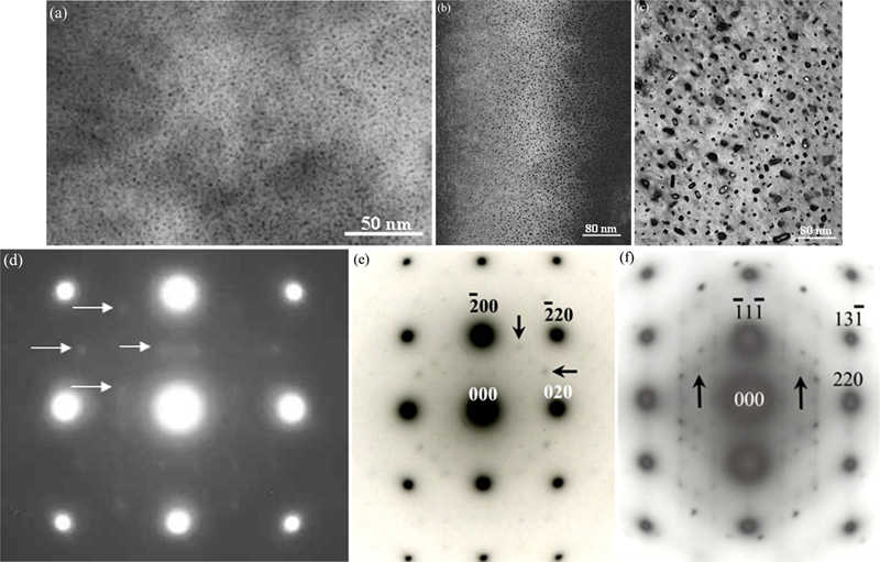
Transmission electron micrographs in a <001>Al projection showing presence of spherical GP zones in naturally aged (2 months) sample, b, c <011>Al projections showing precipitate morphology in underaged and overaged samples respectively; d SAEDP corresponding to Fig. 3a showing diffuse spots (a few marked by arrows) due to spherical GP zones, e, f SAEDPs in <001>Al and <112>Al projections respectively from underaged sample. Marked by arrows in Fig. 3e are couple of diffuse diffraction spots due to GP I zones. Couple of diffraction spots near ½{311}Al positions due to GP II zones are marked by arrows in Fig. 3f
Consideration of Fig. 3, together with our detailed TEM studies, showed that the naturally aged samples contain only GP zones, and the underaged samples contain a combination of GP zones and very fine η′ precipitates. Such precipitates are shearable. In the peak aged temper, the η′ precipitates are the dominant one, and the size ranges of the η′ precipitates are such that the strengthening mechanism involves both cutting and bowing of η′ precipitates by dislocations. In the overaged temper, η′ precipitates further coarsen, and η [i.e. the equilibrium Mg(ZnCuAl)2 phase] precipitates are even observed to nucleate upon dislocations in the matrix. Such precipitates are non-shearable. These microstructural features readily explain the observed homogeneous deformation in the overaged sample (refer to Fig. 2c), pronounced strain localisation in the underaged sample (refer to Fig. 2b) and imply that the solutes present in large amounts in the solid solution effectively disperse the slip and tend to overcompensate the strain localisation caused by shearing of GP zones by dislocations (refer to Fig. 2a).
The tensile properties presented in Table 1 show that the degree of workhardening, as reflected by the values of workhardening exponent n, is the highest in the naturally aged condition. Upon artificial aging, the n value continuously decreases up to the peak aged condition following which the n increases to higher values than those in the peak aged condition. In the underaged condition, where the deformation occurs by shearing of precipitates, there is little workhardening. The shearing of precipitates does not allow additional dislocation storage, and the deformation occurs by planar coarse slip. In the present work, the selection of heat treatment condition for the underaged temper is such that considerable amounts of solutes are already out of the solid solution to form thereafter only shearable precipitates in the microstructure. This unique microstructural feature/condition is understood to be responsible for the least increase in the strength properties in the underaged alloy upon changing the test temperature from ambient to −50°C.
On the other hand, in the overaged condition, when the deformation occurs by bowing of dislocations between the non-shearable precipitates, it builds up dislocation loops around the precipitates. The effective obstacle spacing for a subsequent dislocation to bow between the particles reduces and the stress field developed by successive dislocation looping is substantial. The necessity to retain continuity between the non-shearable precipitates and the matrix would further generate dislocations to create a dislocation cell structure upon the precipitates. A combination of these well documented factors explains why workhardening is much greater when deformation occurs through bypassing of precipitates.6 This, in turn, explains an increased value of n in the overaged condition compared to that in the peak aged temper (refer to Table 1). This effect is obviously more pronounced at −50°C because of the increased rate of workhardening due in turn to the increasing values of shear modulus with decreasing temperatures. These explanations are consistent with the trends of increasing values of Δ0·2PS and ΔUTS from underaged to overaged condition, as shown in Table 1.
The present results are, therefore, consistent with the explanations that in the naturally aged condition, the solutes present in large amounts in the solid solution contribute to the maximum rate of workhardening overcompensating the strain localisation caused by shearing of GP zones by dislocations. This gives rise to the maximum increase in the strength properties of the material upon changing the test temperature from ambient to −50°C (note the corresponding Δ0·2PS and ΔUTS values, as shown in Table 1).
Table 1 further shows a decreasing trend in the percentage elongation from naturally aged to overaged condition. Associated with this, there is a change in the fracture surfaces of the tensile samples from predominantly shear with partly ductile dimple type of fracture in the naturally aged condition to predominantly ductile dimple type fracture in the overaged condition. Figure 4 represents SEM fractographs obtained from naturally aged, underaged, peak aged and overaged samples respectively tested at ambient temperature. These results (i.e. the decreasing trend in the tensile elongation together with the concomitant changes in the fracture surfaces) are considered to be due to the increase in the number density of the void nucleating grain boundary precipitates {in this case, η[Mg(ZnCuAl)2]} and width of the precipitate free zones around the grain boundary with aging.7
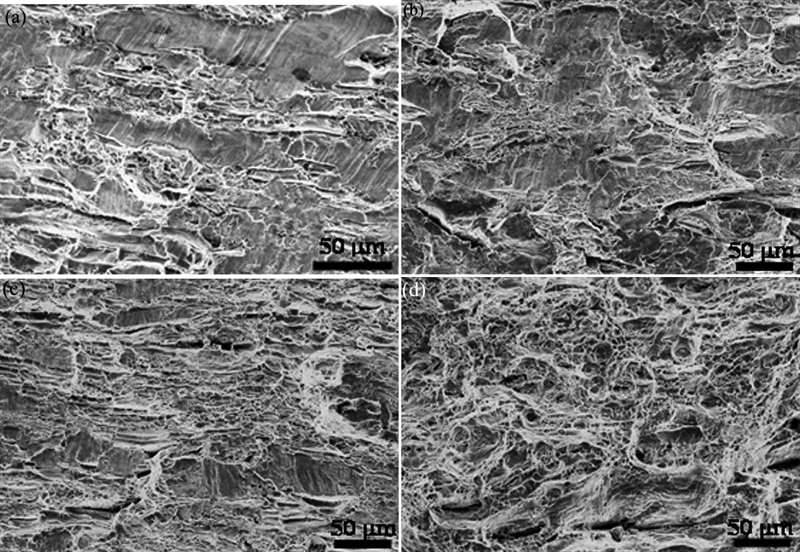
Fractographs (SEM) obtained from a naturally aged, b underaged, c peak aged and d overaged tensile samples tested at ambient temperature
Conclusions
Using Al–Zn–Mg–Cu–Zr alloy 7010, produced in the form of plates and heat treated to different aging conditions, it is shown that the increase in tensile strength properties (both 0·2PS and UTS) due to a change in the test temperature from ambient to −50°C increases in the following order of heat treatment: underaged, peak aged, overaged and naturally aged. The strength increment is maximum in the naturally aged condition and is the least in the underaged condition.
Footnotes
Acknowledgements
The authors wish to acknowledge the financial support from the Defence Research and Development Organisation (DRDO), Government of India.