
Abstract
Using chromium wires as starting material, an iron based composite coating reinforced by in situ (Fe,Cr)7C3 particles, with a thickness of 4·0 mm, was fabricated on the surface of the ductile cast iron substrate, by means of a centrifugal casting technique. The microstructure and properties of the composite coating were investigated by optical microscope, X-ray diffraction, scanning electron micrograph, energy dispersive spectrum, microhardness tester and pin on disc wear tester. Results show that the composite coating consists of primary (Fe,Cr)7C3 carbides as the reinforcing phase and interdendritic (Fe,Cr)7C3/γ eutectics accompanied by negligible graphite nodules as the matrix. The composite coating is metallurgically bonded to the ductile cast iron substrate. Under the condition of dry sliding with loads, the composite coating offers virtually a unique wear resistant behaviour compared with that of unreinforced ductile cast iron material.
Introduction
Wear is one of the three most frequently encountered failure modes for moving metallic mechanical components.1 Recently, the demands on the lifetime and performance of worn components are continuously increasing. From the standpoint of the applications, the carbide particles/Fe based composites generated in situ have the potential advantages in terms of wear resistance, production cost and efficiency, but these composites suffer from a great loss in ductility and toughness due to the incorporation of non-deformable carbide particles, which limits their wide applications. It is desirable that only the surface layer of the component is reinforced by carbide particles, while the bulk of the component retains the original composition and structure with higher toughness. Up to date, considerable efforts have been reported with respect to surface modification of component towards improving their wear resistance behaviour, i.e. powder metallurgy,2 laser cladding3 and plasma spray.4 However, in order to obtain the ideal solidified microstructure in surface composite coating, the critical control of processing parameters is necessary for the existing techniques. Furthermore, the thickness of the surface coating produced by these processing techniques is limited to micrometre scale dimensions, which cannot significantly prolong the service life of the parts.5
The ceramal phase (Fe,Cr)7C3 has a very high hardness (1100–1800 HV)6 and a very strong inherent atomic bonding. The high hardness makes the (Fe,Cr)7C3 very difficult to be plastically deformed when interacting with the abrasive particles during the dry sliding wear process, and hence, it is an excellent candidate as reinforcing phase of wear resistant composite. Another material is ductile cast iron, which has good ductility and high strength; it has been used widely in machine, automobile, mining industries and so on as a structural material. However, as a wear resistant material, its application is still limited.7 – 9 In this paper, an iron based composite coating reinforced by in situ (Fe,Cr)7C3 particles was produced on the surface of ductile cast iron by a centrifugal casting technique, and the microstructure and properties of the composite coating were investigated.
Experimental
Chromium wires (0·25 mm in diameter) and ductile cast iron were used as the raw materials. In order to obtain the high volume fraction of the (Fe,Cr)7C3 phase, the original materials should contain relatively high Cr and C contents; their chemical compositions are Fe–3·61C–2·50Si–0·28Mn–0·45Cu–0·04Cr–0·017P–0·014S (wt-%) for ductile cast iron and Fe–0·12C–0·79Si–17·54Cr–0·011P–0·013S (wt-%) for Cr wire.
In order to obtain high quality composite coating reinforced with (Fe,Cr)7C3 particles, five steps were carried out as follows.
First, the Cr wires were weaved into nets, in which the pore size was 0·8 mm. Second, three layers of the Cr wire nets were wrapped into cylinder and firmly bonded to internal wall of a pipe mould of the horizontal centrifugal machine, as shown in Fig. 1a. Third, the molten of ductile cast iron was produced in medium frequency induction furnace and at 1350–1400°C poured into the pipe mould of the horizontal centrifugal machine; the rotary speed of the centrifugal machine was 1340 rev min−1. Both of the arrows in Fig. 1a indicate the rotary and horizontal movement directions of the pipe mould respectively. Finally, the ring component was removed out of the pipe mould of the horizontal centrifugal machine after solidification, and the composite coating was formed on the ductile cast iron substrate, as shown in Fig. 1b.
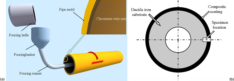
Schematic diagrams of a centrifugal casting and b ring component
When the ring component cooled to room temperature, the metallographic sample was cut and polished for investigations by scanning electron microscopy, energy dispersive spectroscopy, X-ray diffraction and microhardness tester. Cylindrical pin specimens 6 mm in diameter and 25 mm in length were prepared from the ring component (Fig. 1b). Two-body abrasive wear tests were performed with a pin on disc tester (Plint Tribology model TE 67). The pins were loaded against a rotating disc, which carried a bonded abrasive SiC paper of 240 grit (∼60 μm). The applied normal loads were 4·9, 9·8 and 14·7 N. The weight losses of the pins were measured at the same interval in an analytical balance of 0·1 mg precision. The unreinforced ductile cast iron was selected as the reference specimen.
Results and discussion
X-ray diffraction analysis
Figure 2 shows the X-ray diffraction pattern of the composite coating; the main phases consisted of (Fe,Cr)7C3, austenite(γ-Fe) and small traces of (Fe,Cr)23C6. No Cr phase exists in the composite coating, where (Fe,Cr)7C3 and (Fe,Cr)23C6 are newly formed carbides, and this fact indicates that the expected reinforcement of carbides can be synthesised in situ through this method.
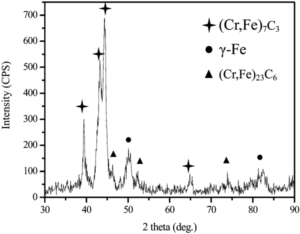
X-ray diffraction pattern of composite coating
Microstructure
The general morphology of the as prepared composite coating was analysed by optical microscope, as shown in Fig. 3a, revealing that the reinforcements were formed in the original place of Cr wires. The reinforcements can be relatively, uniformly distributed in the matrix for the application of Cr wire nets. Furthermore, it can be seen that the composite coating is the compacted structure and the bonds between the reinforcements and matrix, as well as between the composite coating and the ductile iron substrate are high quality metallurgical bonds. This is due to the effect of the centrifugal force; the molten can fill promisingly into the pores of Cr wire nets, and the Cr wires can be instantaneously melted by heat of the molten of ductile iron in the twinkling of pouring.
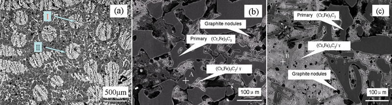
Micrographs of composite coating
To reveal the detailed microstructure of the reinforcements, the higher magnification micrographs of the centre and the side of the reinforcements are shown in Fig. 3b and c, showing that the reinforcements mainly consisted of large primary (Fe,Cr)7C3 carbides and eutectic structure; the primary phases present different shapes including irregular block, strip-like, etc., and they have been surrounded by the interdendrites eutectics (Fe,Cr)7C3/γ as matrix with relatively low Cr and C elements. Energy dispersive spectroscopy analysis results indicate that the average chemical composition of the primary phase (point A of Fig. 3b) and the fine interdendrite eutectics (point B of Fig. 3c) are 47·68Cr–27·53Fe–24·79C and 10·21Cr–61·34Fe–28·45C (at-%) respectively. A few of graphite nodules can be found in Fig. 3b and c; they act as a solid lubrication to improve the wear resistant behaviour of the composite coating. On the other hand, a larger number of graphite nodules can be detected in the ductile cast iron substrate, and it retains the excellent ductility and fracture toughness of the composite.
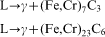
Owing to direct contact with pipe mould of the centrifugal machine, the surface of composite coating has a fast cooling rate. Hence, a larger amount of carbide particles are first precipitated during solidification, and at same time, the C atoms of the molten are depleted for in situ synthesis carbides. As further solidification, the residual melt becomes progressively poor in Cr and C, and more eutectic reactions will take place. Therefore, the following two reactions may take place almost simultaneously at the S/L interface front5
Hardness and wear resistant behaviour
The microhardness profile has also been measured along the cross-section of the coating from outside to inside, as indicated in Fig. 4. The higher hardness of coating is the result of the formation of a larger number of primary (Fe,Cr)7C3 carbides and eutectics (Fe,Cr)7C3/γ. It can be concluded that the thickness of the composite coating is ∼4·0 mm and much larger than that of the composite coating fabricated by laser cladding3 and plasma spray.4
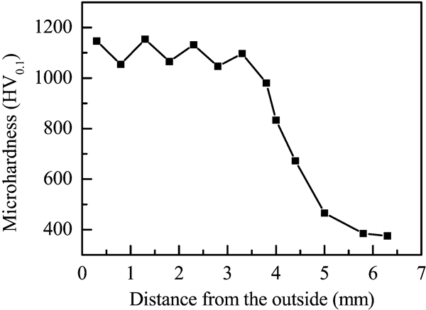
Microhardness profile of composite coating from outside to inside
Figure 5 is the results of the pin on disc wear tests, indicating that the (Fe,Cr)7C3 carbide reinforced composite coating, produced by the centrifugal casting, possesses great wear resistance being 3·9, 4·3 and 4·6 times that of the unreinforced ductile cast iron under 4·9, 9·8 and 14·7 N loads respectively. The morphologies of worn surface for the composite coating and unreinforced ductile cast iron under 14·7 N are shown in Fig. 6 respectively.
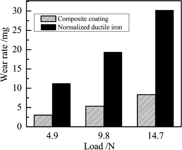
Comparison of wear rates under different loads
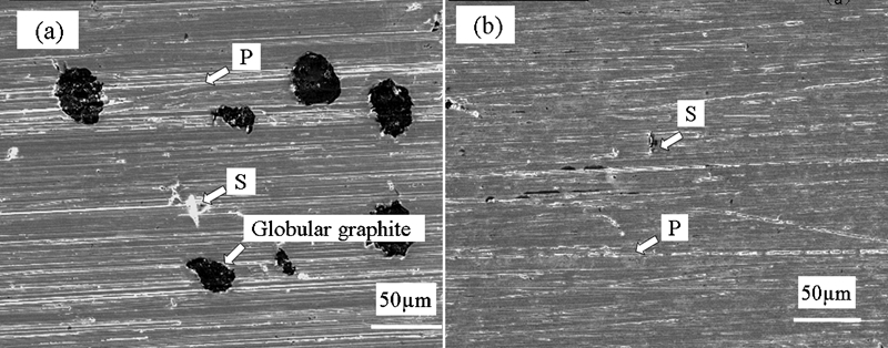
Scanning electron microscopy of surfaces of material after wear resistance tests
During the sliding wear tests, the unreinforced ductile cast iron is displaced to both sides of the wear grooves, forming pile-ups, which, upon subsequent passes by the hard wear abrasion, cause serious plastic deformation, as shown in Fig. 6a, and its worn morphology is very rough with numerous ploughing grooves P and big squeeze traces S.11 However, the composite coating has the microstructure characteristic that hard (Fe,Cr)7C3 carbides are distributed in the matrix; its wear resistance is dependent upon the large volume fraction of hard carbide phase, which acts as physical barrier, and can effectively reinforce the matrix and protect it from serious abrasion. Therefore, the worn morphology of the composite coating is smooth, with only slight microploughings P and squeezes S, as indicated in Fig. 6b. From both pictures, it can be observed that the major wear mechanisms of tested samples are microploughing and squeeze,12 but the wear resistant behaviour of the composite coating is significantly better that of the ductile cast iron.
Conclusions
By means of Cr wire as reactive source, a kind of (Fe,Cr)7C3 reinforced iron based composite coating was produced by centrifugal casting technique on the ductile cast iron substrate. Cr wire can be melted by the heat of ductile cast iron molten during the twinkling of pouring and, the (Fe,Cr)7C3 particles can be in situ synthesised and precipitated during the solidification. The thickness of composite coating is ∼4·0 mm. Compared with the unreinforced ductile cast iron, the composite coating presents a good wear resistance property.
Footnotes
Acknowledgements
This work was supported by a grant from the Research Center for Innovation Engineering in Science and Technology, Shaan Xi Province, China (Grant No. 2007ZDGC-17). The authors also acknowledge the financial support from the Science Foundation of Shaanxi Provincial Education Department (Grant Nos. 09JS032 and 09JS034).