
Abstract
In order to investigate the effect of the gas oxynitrocarburising on the properties of the medium carbon railway axle steel, the steel was gas oxynitrocarburised at five different temperatures for 2 h by applying a low temperature gas multielement penetrating system. The results show that the compound layer composed of γ′-Fe4N and ϵ-Fe2–3N and the oxide layer consisting of Fe3O4 and Fe2O3 are formed on the surface after treatment. The thickness of the compound layer increases with increasing temperature; however, the case depth decreases when the temperature is above the temper temperature of the origin material. The increase in treatment temperature resulted in an increase in the surface roughness. The properties of wear and corrosion resistance are improved, and the fatigue limit of the specimen treated at the optimum temperature, which is 570°C, improves largely compared to that of the untreated one and the one treated by microshot peening.
Introduction
In the recent years, with the increasing demands for high speed and higher axle loads, new challenges to the reliabilities of railway axle arise. For the railway axle, it is required to have the good property of antifatigue, as well as the properties of anticorrosion and antifretting. 1 1,2 To improve these properties, surface hardening process is considered to be applied to the material. For the medium carbon railway axle, induction hardening has been successfully applied to improve the properties.3 However, it is difficult to control the induction hardening due to the variational dimension of the railway axle. In the previous study, microshot peening process was applied to the medium carbon railway axle steel as one kind of cold surface hardening technology, and the result shows that the fatigue property of the material after treatment improves largely, but it is not satisfying.4 As a leading surface engineering process, nitrocarburising has been used to improve wear, corrosion and fatigue resistance of the materials.5 – 10 The nitrocarburising has many advantages, such as a lower treatment temperature, a greater degree of shape and dimensional stability, process safety and reproducibility.8 In the last century, gas nitrocarburising was widely adopted to enhance the properties of the materials because of the advantages of low cost and facility; however, the conventional gas nitrocarburising process requires several hours to get the desired case depth. In the last decades, it was reported that the addition of oxygen was demonstrated to accelerate the nitrocarburising process.11 The authors also developed a low temperature gas multielement penetrating system in recent years, and multielement penetrating, such as gas oxynitrocarburising, can be carried out by this system. 12 12,13 In the oxynitrocarburising process, nitrocarburisation and oxidisation can be carried out simultaneously rather than conducted in two steps consisting of preoxidisation and nitrocarburisation. However, the applicability of this method to the medium carbon railway axle steel has not been performed. The performances of the material after this treatment and the efficiency of this method on this steel have not been investigated; therefore, the properties of the steel treated by oxynitrocarburisation should be studied in detail.
For the railway axle, the failure is mainly caused by the fatigue, and it is necessary to improve the fatigue property by surface hardening process. Meanwhile, anticorrosion and antiwear properties should be improved to satisfy the service demand simultaneously. In the present study, the medium carbon railway steel was gas oxynitrocarburised at five different temperatures; the wear and corrosion tests were carried out, and the influence of temperature on the properties was analysed to determine the optimum treating temperature. Then, the fatigue tests were carried out with the specimens treated at the optimum temperature, and the fatigue property was investigated.
Experimental
The material used in this study was a medium carbon railway axle steel LZ50 (Chinese standard), the chemical composition (wt-%) of which is 0·47C, 0·26Si, 0·78Mn, 0·02Cr, 0·028Ni, 0·15Cu, 0·021Al, <0·014P and <0·007S. The material was normalised for 2·5 h at 860 and 800°C respectively and then tempered for 1·5 h at 570°C. The microstructure of the heat treated materials is ferrite and pearlite. The samples were machined into the size of 10×10×18 mm by linear cutting and polished by emery papers with a mesh of 400–2000. The fatigue specimens were machined into hourglass shape with a minimum diameter of 4 mm and round notch radius of 7 mm. The length of the fatigue specimen was 100 mm, and the elastic stress concentration factor Kt is 1·06.
The oxynitrocarburisation was carried out at 530, 550, 570, 610 and 630°C for 2 h, with a gas mixture of NH3, O2 and additive organic gas (the mixture of C2H5OH, H2O and N2) at 0·11 MPa in a low temperature gas multielement penetrating system, the detail of which can be seen in Ref. 13, and then the samples were cooled in air.
The samples were etched in 4% nital solution at room temperature after polishing and then observed by an optical microscope (model CXZIFSI, Olympus Optical Co., Ltd Tokyo, Japan). The microhardness was measured with a Vickers microhardness tester HRD-1000 using a 0·98 N load and holding for 15 s, and the effective treated case depth was defined as the depth at which the hardness was 50 HV larger than that of the matrix. The phase constitution at the surface of the sample was measured by an X-ray diffractometer (Philips X'Pert PRO SUPER, PANalytical, Almelo, The Netherlands). The measurements were performed at 30 kV and 30 mA with Cu Kα radiation (λ = 1·544 Å) at room temperature.
The surface roughnesses of the samples were measured by a surface profilometer (Kosaka Laboratory, Tokyo, Japan, SE30D), and their values were obtained by taking the average of five times measurement.
The wear test was carried out on an MM-200 block on wheel sliding wear tester in dry condition at room temperature to evaluate the performance of wear resistance. In the tester system, a block specimen (10×10×18 mm in size) is pressed under the applied test load of 200 N against the outer periphery surface of a GCr15 steel wheel (750 HV), the chemical composition (wt-%) of which is: 1·00C–0·25Si–0·30Mn–1·45Cr–0·013P–0·005S, rotating at 200 rev min−1. The test was paused every 10 min, and the wear track was observed during the test. The wear mass loss was measured by an analysis balance with an accuracy of 0·01 mg and was utilised to rate the relative wear resistant properties of the treated samples in comparison with the untreated materials.
The corrosion resistant behaviour was evaluated in an SO2Y/Q-250 salt spray test system. In this test, the samples were exposed to a salt spray generated from a 5 wt-% sodium chloride solution with a pH value ranging between 6·5 and 7·2. The temperature in the chamber was held at 35°C. All the samples were hung inside the testing chamber with plastic strings in a free standing mode to ensure that all sides of the samples got sprayed uniformly for a total exposure time of 144 h. Photographs were taken before and during the exposure to document the surface conditions. The samples were monitored and rated at the exposure times of 2, 6, 24, 48, 72, 96, 120 and 144 h. After exposure, the exposed face of each sample was assigned a protection rating based on the ASTM B537-70 standard.
Rotating fatigue tests were carried out on a four-axle cantilever type rotary bending test machine (RB4-3150-V1, Horkos Corp., Hiroshima, Japan), at a frequency of 52·5 Hz (3150 rev min−1) in laboratory air atmosphere. The round notch surfaces of the untreated specimens were mechanically polished by emery paper with a mesh of 400–2000. However, the surfaces of the treated specimens were remained without polishing.
Results and discussion
Microstructure and microhardness
Microstructure observations of the samples are given in Fig. 1. A loose and black oxide layer is formed on the outermost surface with a thickness varying between 4 and 7 μm and a thicker white compound layer beneath it. As shown in Fig. 2, the thickness of the compound layer increases with increasing temperature. Below the compound layer is the diffusion zone, the depth of which cannot be obtained from the figure directly. For the samples treated at 610 and 630°C, there is a columnar morphology structure under the compound layer due to the high temperature. For all the samples, it can be confirmed that the microstructure of the core remains unaltered after treatment.
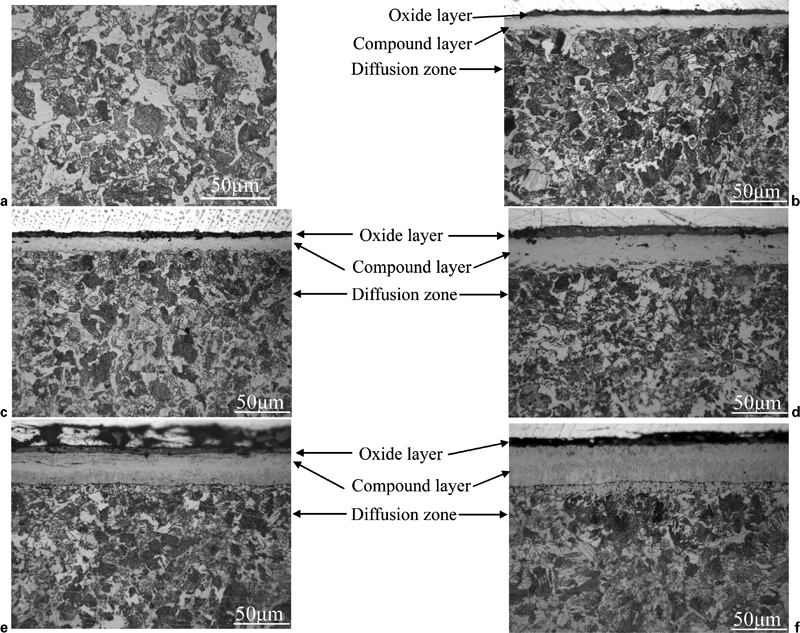
Microstructure observations of untreated sample and samples treated at different temperatures: a untreated; b 530°C, c 550°C, d 570°C, e 610°C; f 630°C
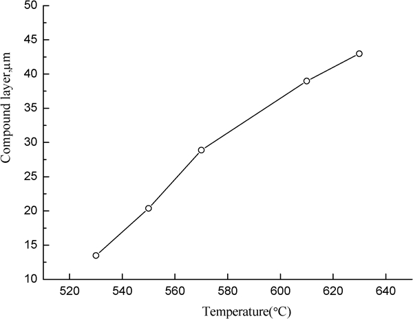
Compound layer thickness varies with treating temperature
The microhardness profile results obtained from the cross-section of all groups of samples are shown in Fig. 3. The microhardness of the oxide layer on the outmost surface is comparatively low, and the compound layer shows the highest hardness plateau. The maximum hardness at the compound layer is in the range of 610–660 HV. The core hardness at 530, 550 and 570°C treating temperatures remains the same as that of the untreated sample. This confirms that the core does not soften by overaging at the treating temperatures below the temper temperature of this material. However, at 610 and 630°C, which are above the temper temperature, the core hardness decreases. The effective case depth of the samples based on 252 HV is given in Fig 4. It is found that the case depth increases with increasing treating temperature when the temperature is lower than 570°C, and the case depth decreases when the temperature is over 570°C. It has been reported that the case depth increases with increasing temperature owing to the greater diffusivity of nitrogen and carbon at high temperature,7,14 whereas, in this study, the case depth decreases at high temperature, and it is caused by the softening of matrix at the temperature higher than the origin temper temperature. Therefore, the treating temperature should match the heat treating temperature when the material was surface treated.
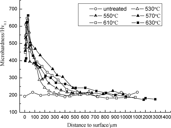
Surface microhardness distributions of samples
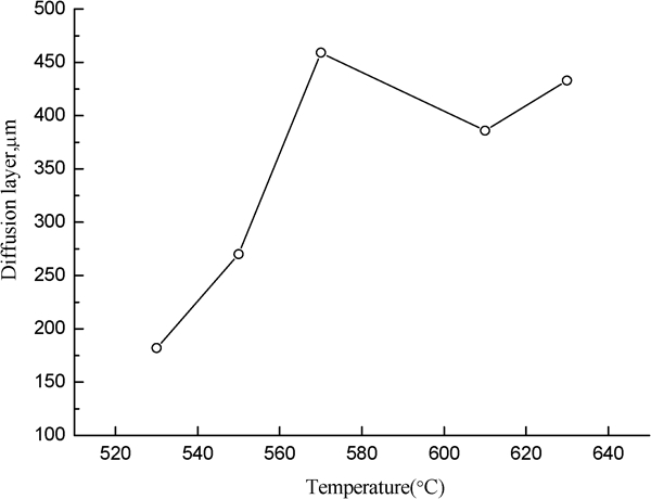
Case depth varies with treating temperature
The results of carbon steel show that, for carbon steels after treatment, only moderate hardness can be obtained.14,15 This is mainly because nitrogen diffuses fairly quickly beneath the surface forming iron nitrides dispersed at greater depths so that surface hardness is comparatively reduced. Since the nitride forming elements have a higher affinity for nitrogen, they prevent diffusion of the nitrogen to a greater depth and instead form very hard stable particles near the surface. However, in this study, a large surface hardness and case depth are obtained after gas oxynitrocarburisation in a comparatively short treating time. Meanwhile, the case depth is larger than the alloy steel treated by this process for the same time.12
X-ray diffraction result
X-ray diffraction patterns obtained from the surface of treated specimens are more or less the same as shown in Fig. 5, which were obtained from the 570°C treated sample. X-ray diffraction analysis reveals that a compound layer consisting of γ′-Fe4N and ϵ-Fe2–3N is formed on the sample surface after the treatment. The oxide layer on the outermost surface consists of Fe3O4 and Fe2O3. However, the carbonisation in the compound layer is too little to be detected.
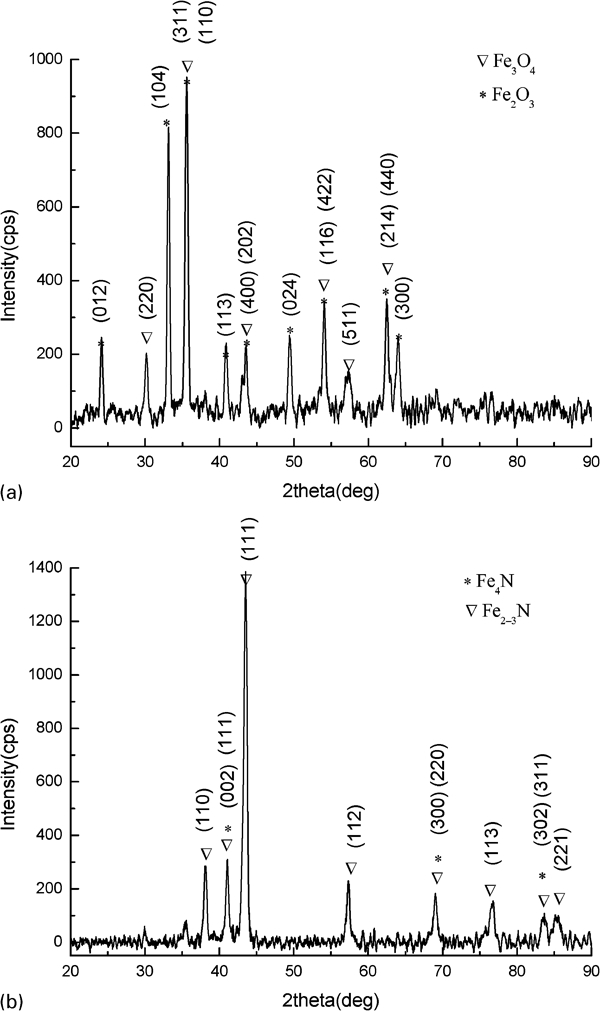
X-ray diffraction patterns of a oxide layer and b compound layer
Surface roughness
The surface arithmetical mean roughnesses Ra of the treated samples are displayed in Fig. 6 and that of the untreated sample is 0·1139 μm. It can be seen that the roughness increases after treatment. The roughness of the surface increases with increasing treating temperature. Minimum roughening occurs at 550°C, and the roughnesses increase largely at the temperatures above 570°C. The increase in the surface roughness is mainly due to the formation of the oxide layer on the surface and the surface relief caused by volumetric expansion. During the process, a loose oxide layer forms on the outermost surface, and it becomes looser with increasing temperature, which can be confirmed by the microhardness profile results shown in Fig. 3. Although the surface roughnesses increase after the treatment, as for the service conditions of machine parts, it is considered that these changes in surface roughness are within the usual range.
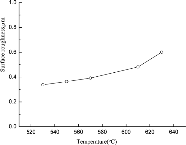
Surface roughness values Ra varying with treating temperature
Wear resistance
Wear rate curves obtained from untreated and treated specimens are shown in Fig. 7. The results are plotted in graphs showing the weight loss against time for specimens treated at different temperatures. It can be seen that the property of wear resistance is improved after the treatment. The weight loss rate of the treated sample is comparatively high in the first few minutes due to the existence of oxide layer. Afterwards, the weight loss rate of the treated samples is lower than that of the untreated one. For the treated samples, the compound layer formed beneath the oxide layer has the highest hardness and is beneficial to the wear resistance. Therefore, the sample treated at 630°C, which has the largest depth of compound layer, has the lowest wear loss at the early stage. However, its wear loss will increase when the hardened case is worn. Therefore, the best wear resistance property is obtained from the 570°C treated sample, and this can be confirmed from the hardness curves shown in Fig. 3.
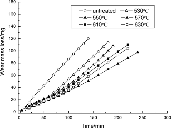
Wear test results of samples
The wear tracks on the specimen surfaces were observed by an optical microscope. There are two major categories of wear mechanisms: adhesive and abrasive wear.16 Adhesive wear occurs when the contact pressure between the rolling surfaces is high enough to cause local plastic deformation and welding between the contacting asperities. Abrasive wear occurs when hard debris particles are indented and make a groove in the rolling surface of the materials. Figure 8a was obtained after 10 rolling cycles, and it shows adhesive wear track. The large wear loss at the initial minutes is correlative with the debris of oxide layer separating from the surface. As shown in Fig. 8b, at the compound layer, the wear tracks show abrasive wear track and its profile is smooth.
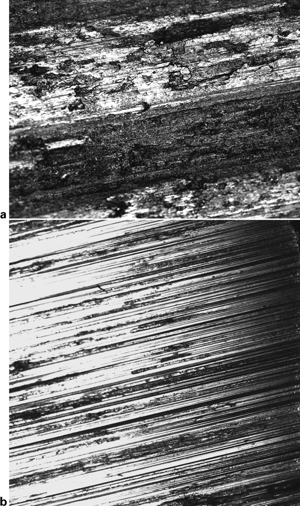
Optical micrographs of wear tracks obtained at a oxide layer and b compound layer
Corrosion resistance
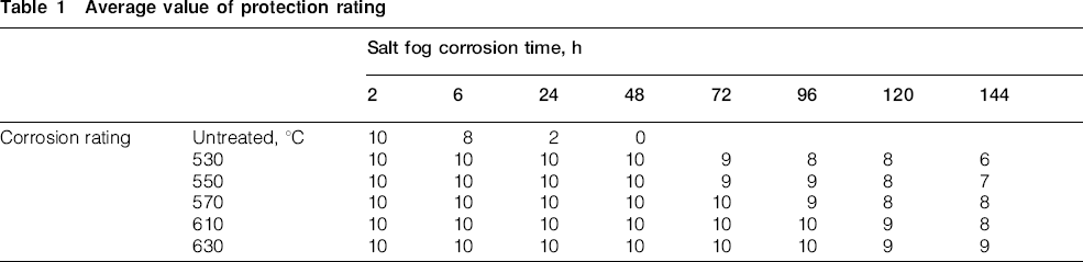
Table 1 shows the results of the samples after salt spray test for 144 h exposure. It is observed that corrosion in untreated samples started after 48 h of exposure uniformly throughout the sample, and there is no corrosion in treated samples even after 48 h of exposure. The excellent corrosion resistance property of the treated samples resulted from the compound layer of γ′-Fe4N and ϵ-Fe2–3N and the Fe3O4 in the oxide layer, all of which are chemically stable in the corrosive medium.17 – 19 According to the results in Table 1, the average value of the protection rating increases with increasing treating temperature. Therefore, it can be also concluded that the improvement of corrosion resistance is mainly attributed to the compound layer on the surface.
Average value of protection rating
Fatigue property
From the results above, it can be concluded that the sample treated at 570°C has the best global property so that the optimum treating temperature is 570°C for this material. To investigate the fatigue property, the fatigue test was conducted with the specimens untreated and treated at 570°C.
Fatigue limits of the specimens obtained from the tests are presented in Table 2. It is noticed that the fatigue limit of the specimen treated is 580 MPa, which improved 120% compared to that of the untreated one. The improvement of the fatigue limit is attributed to the combining effect of higher case hardness and compressive residual stresses. The residual stress is caused by nitrogen being taken into solution in the matrix and the formation of nitride precipitates. The fatigue limit of this material treated by microshot peening is given in Table 2, and the fatigue limit of the specimen is improved by 35% after microshot peening treatment compared to that of the untreated one. This is caused by the different levels of the relaxation of residual stress and different surface hardnesses. For the microshot peened specimen, there is large stress relaxation during the fatigue test.4 Meanwhile, there is no evidence of residual stress relaxation for the oxynitrocarburised specimens. The depth of the hardened layer and value of the surface hardness of specimens oxynitrocarburised are also larger compared to that of the microshot peened one. Therefore, gas oxynitrocarburising is recommended as the feasible process to improve the fatigue resistance property of the material.
Fatigue limit of specimens

Based on the results above, it can be seen that various kinds of properties improve largely after the oxynitrocarburisation, and it is possible to apply this process technology to the medium carbon railway axle, which is used widely in China. Meanwhile, further studies are needed and will be carried out in future work to make this laboratory finding into an industrially viable technology for the real structure.
Conclusion
In this work, the medium carbon steel was gas oxynitrocarburised at five different temperatures by applying a low temperature gas multielement penetrating system. After the treatment, a duplex layer made up of oxide and compound layers is formed on the sample surface. The compound layer consists of γ′-Fe4N and ϵ-Fe2–3N, and the oxide layer consists of Fe3O4 and Fe2O3. The thickness of the compound layer increases with increasing temperature; however, the case depth decreases when the temperature is above 570°C, which is the temper temperature of the original material. This indicates that the treating temperature should match the heat treatment temperature when the material is treated by oxynitrocarburisation. The results of wear and corrosion tests show that the properties of wear and corrosion resistance are improved after the treatment. The best wear resistance property is obtained from the 570°C treated sample, and this is in accordance with the distribution of the hardness curves, while the corrosion resistance property increases with increasing temperature. The fatigue result shows that the fatigue limit of the specimen treated at the optimum temperature, which is 570°C, improves largely compared to that of the untreated one, and it is also larger than that of the one treated by microshot peening.
Footnotes
Acknowledgements
This work was supported by the National Natural Science Foundation of China (grant no. 50671086), National Basic Research Program of China (grant no. 2007CB714705), State Key Laboratory Independent Research of China (grant no. 2009TPL_T04) and Fundamental Research Funds for the Central Universities (grant no. SWJTU09CX060).