
Abstract
Slight misalignments of the ladle shroud in a multistrand continuous casting tundish can lead to significant differences in the amounts of slag entrained into individual moulds during transient operations. In this full scale water modelling work, the effects of ladle shroud alignment on steel quality was measured in terms of ‘slag’ entrainment into the individual moulds. The ladle shroud was purposefully biased by about 4–5° off vertical, and the numbers of ‘slag particles’ entering individual strands of the four‐strand billet caster were measured during a ladle change and compared with the no bias condition. Given the great sensitivity of steel quality to this slight misalignment during a ladle change, possible remedial actions are discussed for equivalent steel plant operations.
List of symbols
empirical constants
rate of production of k, kg m−1 s−3
kinetic energy of turbulence per unit mass, m2 s−2
submerged entry nozzle
instantaneous velocity component, m s−1
rate of energy dissipation, m2 s−3
Introduction
The enhancement of steel quality during continuous casting operations has been a long lasting issue, and the challenge still remains. Researchers around the globe have reported on steel quality issues over the last four decades. Guthrie1 already addressed the role of fluid flows in metal processing operations and strongly emphasised their importance to liquid metal quality. Sahai2 summarised the modelling of melt flows in continuous casting tundishes during the Brimacombe Memorial Symposium. He emphasised the importance of contriving good melt flows within tundishes for achieving high quality clean steels, noting that this can be achieved by good tundish design and optimum volumetric flowrates of liquid steel.
Many researchers have reported on inclusion removal in a tundish. Zhang et al. 3 proposed three modes of inclusion removal from molten steel in the tundish, namely, floatation to the free surface, collision and coalescence of inclusions to form larger ones and adhesion to the lining solid surfaces. Those researchers studied the three‐dimensional fluid flow with and without flow control devices. The results indicated that flow control devices effectively control the strong stirring energy within the inlet zone. Flow control devices were also favourable for inclusion removal. The total removal ratio was 51% without flow control devices, wherein inclusions with radii >72 μm were totally removed. This increased to 79% with flow control devices where inclusions with radii >61 μm were totally removed. Of the 79% eliminated, removal by floatation was 49·5% and removal by adhesion was 29·5%. The collision and coalescence mode was a better way to remove smaller size inclusions, as the number of collisions per unit time per unit volume of steel was much higher for smaller inclusions than for bigger ones.
Javurek et al. 4 considered the removal of non‐metallic inclusions due to buoyancy forces in continuous casting tundishes. They found the reasons why the particle separation is worse than the calculated maximum possible removal rate. The reasons were unsuitable fluid flow patterns and turbulent diffusion of particles. They also concluded that residence time distribution curves are an inappropriate measure for estimating particle separation in tundishes. The use of direct calculation and computational fluid dynamics simulation was recommended. Thomas and Bai5 summarised the mechanisms of formation, methods of detection and ways to prevent, tundish nozzle clogging, focusing on the role of computational models in quantifying the non‐composition related aspects. They classified mechanisms for tundish clogging into four main types, namely, the transport of oxides present in the steel to the nozzle wall, air aspiration into the nozzle, chemical reaction between the nozzle refractory and the steel and, lastly, steel solidified in the nozzle.
However, in practice, a clog can be a combination of two or more of the above types. They mentioned that clogging can be best detected during casting by simultaneous monitoring of several different parameters, such as argon back pressure, nitrogen pick‐up by the steel, mould level fluctuations and flow control position relative to casting speed. Solutions to reducing clogging problems were also mentioned by them. They include minimising inclusions by improved steelmaking practices, optimising fluid flow and melt transfer processes, controlling steel alloy additions, slag and refractory compositions, improving nozzle material design, and avoiding air aspiration. Rogler et al. 6 reported the probability of inclusion removal in a tundish by gas bubbling. They7 also performed physical modelling of inclusion removal in a tundish by gas bubbling. They used water as the analogue of steel and linear low density polyethylene (ρ = 0·92) as an analogue for inclusions. They concluded that separation efficiency of inclusion particles within the flowing liquid bath in a tundish is influenced by a number of factors, like overall fluid flow behaviour, chemical and physical nature of the inclusion, size of the inclusions and rates and mechanisms of particle capture by various potential particle sinks. From their study, they showed that flow control devices enhanced particle separation efficiency, and properly sized bubbles induced the highest particle separation efficiencies.
However, concerning the entrainment of tundish slag, a very important phenomenon during ladle changes, has not been considered in most cases. Solhed et al. 8 and Solhed and Jonsson9 included slag entrainment in their work, but the majority of the work to date has been carried out at the McGill Metals Processing Centre (Montreal, Canada) with Guthrie. Kim10 and Ray11 in their masters and PhD thesis at McGill University included a lot of results on slag entrainment. Similarly, slag entrainment was a very important parameter in designing new flow modifiers for the industry.
In the present study, slag entrainment was used as a parameter to determine the effect of ladle shroud misalignment. It was seen from full scale water model experiments that a slight bias of the shroud can cause catastrophic effects on steel quality in one of the strands. Mathematical modelling has been carried out using a biased shroud, and flow fields and turbulent kinetic energies have been examined. A correlation between physical and mathematical modelling results was observed. As slight bias in the position of the shroud is inherent in the industry, some remedial measures have been discussed.
Physical modelling
Physical modelling was carried out using a full scale water model of a 12 tonne, delta shaped, four strand tundish, as shown in Figure 1 Figure 2 Figs. 1–3. The slag phase was simulated using polyethylene beads of densities around 900 kg m−3. A water inflow rate of 0·17 m3 min−1 was used in the tundish, and a steady state height of 500 mm of water was maintained. The ladle change operation was simulated by stopping the flow of water passing through the shroud for 3 min while the tundish drained and then opening the slide gate fully to achieve a refilling rate of ∼500 L min−1 to regain the height of 500 mm as soon as possible. During this operation, due to high turbulence experienced from the plunging free jet of steel, the slag layer adjacent to the entry region is disrupted. Many ‘slag droplets’ are entrained within the ‘steel’, and many of these can then pass through each strand. By counting the numbers of particles collected in each strand, relative performances are assessed, using the full scale water model tundish. Following operational difficulties, the problem was finally resolved as a ladle shroud misalignment. To test this hypothesis, the ladle shroud was purposefully biased by about 4–5° off the vertical, along the longitudinal axis of the tundish, in order to determine the effect of shroud bias on slag entrainment, according to the different flow modifiers used in the water model experiments.
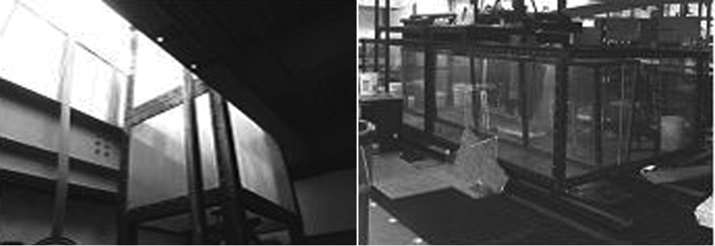
Full scale water model tundish
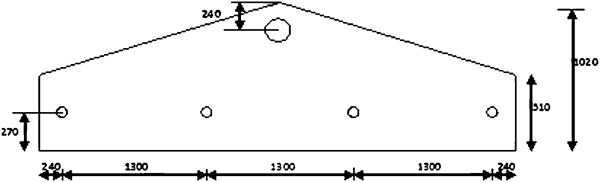
Schematic drawing of the tundish bottom in present study (all dimensions are in millimetre)
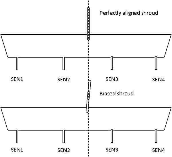
Schematic drawing representing biased shroud condition
Mathematical modelling
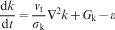
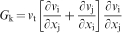
The domain of calculation was drawn using basic computer aided design tools and discretised in GAMBIT 2·4·6, as shown in Fig. 4. The shroud was biased by 5° off the vertical in the design. The simulations were carried out using Fluent 12·0. The fluid (water) in the tundish and shroud were considered as Newtonian and incompressible. The standard k–ϵ turbulence model of Launder and Spalding12 was used, where k is the kinetic energy of turbulence per unit mass and ϵ is the rate of turbulence energy dissipation. Thus


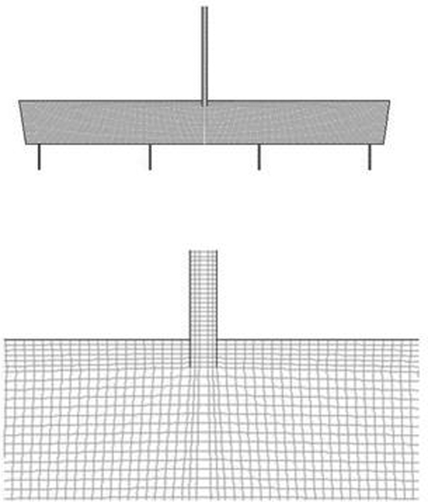
Meshing of tundish in GAMBIT 2·4·6
The velocity inlet boundary condition was used for the inlet, and outflow boundary conditions were used for the outlets. The top surface was set as a free surface, and all other surfaces were walls with the no slip condition. To model the non‐submerged shroud, during refilling of the tundish, a free jet condition was considered.
Results and discussion
physical modelling
For physical modelling, three types of arrangements were considered, namely, the bare tundish, an impact pad and 0·381 m high dams on either side of the shroud. The results of slag entrainment, during a ladle change with a perfectly aligned shroud, are shown in Table 1 Table 2 Tables 1–3 and Figure 5 Figure 6 Figs. 5a, 6a and 7a . Seven experiments were preformed for each arrangement, and the average was taken.
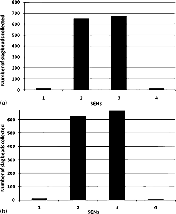
Amount of slag entrained in different submerged entry nozzles (SENs) in bare tundish
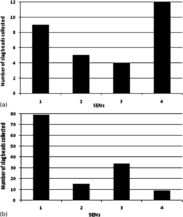
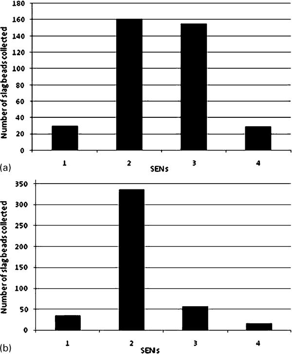
Amount of slag entrained in different SENs in tundish with impact pad
Amount of slag entrained in different SENs in tundish with 0·381 m high dams on either side of shroud
Slag entrainment in bare tundish with perfectly aligned shroud*
*SEN: submerged entry nozzle.
Slag entrainment in tundish with impact pad and perfectly aligned shroud*
*SEN: submerged entry nozzle.
Slag entrainment in tundish with 0·381 m dams on either side of perfectly aligned shroud*
*SEN: submerged entry nozzle.
Symmetry can be clearly seen in the amount of slag entrained in individual strands on either side of the shroud. For the bare tundish, there is much more slag in the inner strands as compared to the outer ones. For the impact pad arrangement, there is more slag in the outer strands as compared to the inner strands. For the 0·381 m high dams, more slag entrainment occurs in the inner strands than in the outer strands. However, if the results are compared in terms of total slag entrainment, the impact pad arrangement is the best.
The results of slag entrainment with a biased shroud are shown in Table 4 Table 5 Tables 4–6 and Figure 5 Figure 6 Figs. 5b, 6b and 7b . For the bare tundish, the effect of the bias is not clearly seen because a lot of slag is entrained in the inner strands. However, if only the outer strands are considered, there is more slag going through SEN 1. For the impact pad arrangement, it is clearly seen that much more slag is entrained in SEN 1 compared to SENs 2, 3 and 4. In addition, for the 0·381 m dam arrangement, more slag goes through SEN 2 than SENs 1, 3 and 4. Therefore, it is seen that more slag is entrained in the SENs located in the direction of the bias. From the above results, it can be inferred that if there are biased flows towards one side of the tundish, i.e. towards SEN 1 and 2, then this causes more slag entrainment. To confirm this, a red dye was injected through the biased shroud, and it was observed that the dye spread more rapidly in the region containing SENs 1 and 2 than in the region with SENs 3 and 4.
Slag entrainment in bare tundish with 5° biased shroud
*SEN: submerged entry nozzle.
Slag entrainment in tundish with impact pad and 5° biased shroud
*SEN: submerged entry nozzle.
Slag entrainment in tundish with 0·381 m dams on either side of 5° biased shroud
*SEN: submerged entry nozzle.
Mathematical modelling
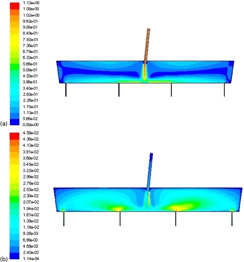
For the bare tundish arrangement, velocity contours and turbulent kinetic energy (TKE) contours are shown in Fig. 8. It can be clearly seen that due to the free jet, there are higher velocity areas in one‐half of the tundish containing SENs 1 and 2. Furthermore, it can be seen that TKE is more in the SEN 1 and 2 regions as compared to the SEN 3 and 4 regions.
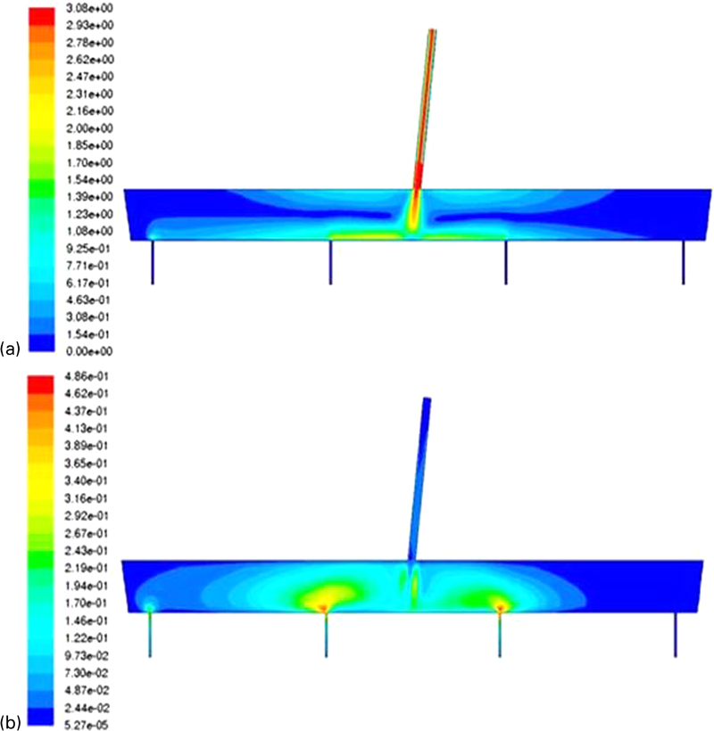
Contours of a velocity (m s−1) and b turbulent kinetic energy (m2 s−2) with biased shroud in bare tundish (non‐submerged)
This explains why more slag is dragged preferentially to one side of the tundish, causing more slag entrainment in the direction of the bias. Similar simulations were carried out with an impact pad arrangement, and the results are shown in Fig. 9. Similar results have been obtained with more TKE in the SEN 1 and 2 region. Therefore, the experimental results can be nicely correlated with the mathematical model predictions. Some simulations were done with the biased shroud in the submerged condition, and it was seen that the bias has no effect when the shroud is submerged. The flow fields and TKE contours are equivalent on either side of the shroud. This is shown in Fig. 10. The result is logical because the momentum of the fluid coming from the shroud is absorbed by the surrounding fluid in the tundish. Similarly, no slag particles are entrained, as there is no direct contact between the impinging jet and the upper slag phase, as what is happening in the non‐submerged condition.
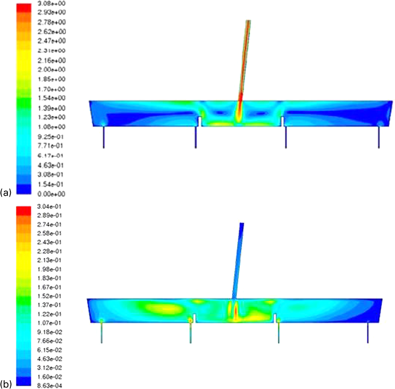
Contours of a velocity (m s−1) and b turbulent kinetic energy (m2 s−2) with biased shroud in tundish with impact pad (non‐submerged)
Contours of a velocity (m s−1) and b turbulent kinetic energy (m2 s−2) with biased shroud in bare tundish (submerged)
Remedial measures
As seen from above, shroud misalignment with an exposed ladle shroud can be catastrophic in terms of transient steel quality to the strands, and some remedial measures are called for. From the numerical predictions, it is clear that, in the submerged condition, a biased shroud has no effect on flow and TKE fields, and slag is not entrained. This suggests that opening up of a new ladle when the ladle shroud is above the level of steel in the tundish should be avoided. That procedure is possible with bell shaped ladle shroud nozzles, which can accommodate gas pockets but not with straight bore nozzles more commonly used within the industry. For these, one opens up a new ladle with the ladle shroud clear of the melt. This precaution avoids exploding ladle shrouds and/or dangerous subsurface gas explosions. Given that the collector nozzle shroud is reset from one ladle to another, the nozzles are invariably slightly biased (e.g. >90%). Therefore, the time period during which the shroud is exposed and slag is entrained must be minimised. In this regard, a three‐plate slide gate shroud is superior to the two plate slide gate system, since the latter precludes lateral movements during operations.
Assuming normally designed shrouds with a two‐plate system are being used, the first measure is to minimise exposure times before resubmergence of the shroud so as to limit the amount of slag entrainment. One technique would be to raise the steel level in the tundish above the normal operating height (500 mm in the case modelled) a few minutes before the end of a ladle pour. This allows time for the collector nozzle to be decoupled from the emptied ladle, the turret rotated to the new ladle and the collector nozzle refitted to the collector nozzle of the new ladle with a gasket. This procedure would be carried out such that the level of steel in the tundish would be just below the end of the shroud collector nozzle once ended. As soon as the level of steel within the tundish drops below the end of the ladle shroud, the new ladle should be opened immediately, and the ladle shroud quickly resubmerged. Normal practices require 3–4 min to make a ladle change, during which liquid steel has fallen well below the end of the collector shroud.
Conclusions
The present study indicates that a slightly biased shroud can be a major problem in terms of transient steel quality during a ladle change. The physical modelling results correlated well with the mathematical modelling predictions. A submerged shroud operation would be better than the non‐submerged operation during a ladle change as indicated from the numerical model predictions, but practical difficulties do not normally allow for this.