
Abstract
A novel study to characterise electric arc furnace (EAF) slags in the production of duplex stainless steel at the process temperatures was performed. The investigation is focused on determining the microstructural evolution of the EAF slag during and at the end of the refining period. In this regard, slag sampling was done at three stages from seven EAF duplex stainless steel heats (21·5–22·5 wt‐%Cr, 1·6–5·7 wt‐%Ni and 0·3–3·2 wt‐%Mo). More specifically, the samples were collected before FeSi addition, after FeSi injection and just before tapping. Collected samples were analysed by light optical microscopy and SEM energy dispersive X‐ray spectroscopy to characterise the high temperature microstructure of the slag phases. In addition, X‐ray diffraction analysis was used to verify the petrographical results. It was observed that at all process stages, the duplex steel slag contains molten oxides, magnesiochromite spinels and metallic droplets. However, before the FeSi addition, the slag also contains calcium chromite crystals. In this stage, the slag has a high viscosity, which drops to lower level after FeSi injection. Furthermore, depending on the basicity, the slag may contain other solid phases such as perovskite and calcium silicate.
Introduction
The high temperature microstructure of the solid phases within the slag has a large effect on the process features, such as foamability of the slag, chromium recovery, consumption of the ferroalloys and the wear rate of the refractory of the electric arc furnace (EAF). Thus, knowledge about the high temperature microstructure of the slag is essential for a good slag practice.1 This, in turn, plays a leading role for the production of high quality stainless steel grades. In addition, the electrical and material efficiency of the EAF can considerably be improved by a good slag practice. 2 2,3
At the same time, new duplex stainless steel grades are being introduced to replace austenitic stainless steel grades.4 This is due to their cost efficiency, high mechanical properties and good corrosion resistance.5 A duplex stainless steel is defined as one that combines both ferritic and austenitic microstructures.6
As a result of this combination, duplex stainless steel has characteristic properties of both austenitic and ferritic stainless steels. Since duplex stainless steel grades contain lower amounts of nickel and molybdenum than austenitic stainless steel, with the same level of corrosion resistance, they can be produced at a lower cost.7
Standard duplex stainless steel is characterised by a higher chromium content (22%) than standard stainless steel (18%) and a lower nickel content (5·5 against 8%). In other words, the chromium content of the duplex steel grades is generally ∼20% higher than austenitic steel grades. Considering this, the authors believe that the chromium oxide content of the EAF duplex steelmaking slags should be higher than that for standard stainless steel slags. Mostafaee et al. 3 predicted the effect of chromium oxide content on the high temperature microstructure of the standard stainless steelmaking slags in EAF. Figure 1 illustrates the significance of the Cr2O3 content of the slag on the amount of the magnesiochromite (spinel) precipitations within the molten slag. The diagram is drawn for a typical EAF austenitic stainless steelmaking slag at the final stage of the EAF melting process.3
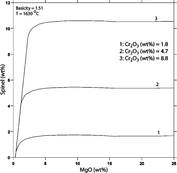
Effect of changes in Cr2O3 content on spinel amount of typical EAF austenitic stainless steelmaking slag
The diagram predicts that the amount of the precipitations increases significantly with the increase in the chromium oxide content of the slag. More specifically, the amount of the spinel particles increases up to five times by increasing the Cr2O3 content of the slag from 1·8 to 8·8 wt‐%. In addition, Kerr and Fruehan8 proposed a relationship between foamability of the slag and second phase particles within the slag. They suggest that a reasonable amount and size of the second phase particles increases the effective viscosity of the slag and thereby its foamability. On the contrary, if the amount and the size of these particles pass particular limits, the foamability of the slag greatly decreases. In this context, it is reasonable to make a distinction between slag from production of duplex stainless steel and austenitic stainless steel considering their different high temperature microstructures, which leads to different physical properties and foamability.
Shortage of high quality duplex steel scrap with an accurate chemical composition combined with additional requirements for a precise composition of certain elements, such as copper,9 forces the melters to charge larger amounts of ferrochromium into the furnace to obtain the required chromium content. To be sure that the large pieces of the charged ferrochromium are completely molten, the temperature in the EAF duplex steelmaking process is generally higher than that for austenitic stainless steelmaking. It should be considered that the stirring in the EAF is often relatively weak. Thus, another difference between the production process of the duplex and austenitic stainless steel in EAF corresponds to the higher production temperature in EAF duplex steelmaking. In addition, owing to the higher chromium content of duplex steelmaking slags, the risk for a larger chromium loss to the slag is high. Here, an improved chromium recovery and a better controlled slag practice are demanded.
An annual growth rate of more than 10% for the global market of duplex stainless steel is expected.4 In spite of this, no experimental or theoretical investigation on the high temperature microstructure of the duplex stainless steel slag in EAF has yet been reported. However, a limited level of experimental study has been performed on the characterisation of the slag in the austenitic stainless steel production. 2 3 10 2,3,10,11 Tossavainen et al. 11 analysed an EAF high alloyed steel slag (Cr2O3 = 3·3%). They could differentiate a spinel phase from the matrix forming phases. The slag sample had undergone a semirapid solidification. Durinck et al. 2 investigated the microstructural evolution of austenitic stainless steel slag samples taken during refining and tapping stage of the EAF process. They showed that, at high temperatures, the austenitic stainless steel slag consists of metallic droplets and solid MgO.(Cr, Al)2O3 based spinels as well as a liquid slag phase. Moreover, they discussed the influence of the slag temperature, basicity and oxygen partial pressure on the solubility of the spinel phase. Mostafaee et al. 3 determined the weight per cent of the solid spinel particles in the slag as well as the amount of the molten slag at the end of the refining stage using the commercial software package Thermo‐Calc.12 In addition, Mostafaee et al. 3 studied the effects of different parameters, such as weight per cent MgO and Cr2O3, temperature and the slag basicity on the amount of spinel crystals in the bulk slag. They concluded that the only critical parameter affecting the total volume of the solid spinels is the chromium oxide content.
The present work is focused on the petrographical characterisation of the microstructure of the duplex stainless steel slags at three different EAF process stages. Microstructural evolution of the slag during and at the end of refining period is investigated, based on the observational study of seven EAF duplex stainless steel heats (21·5–22·5 wt‐%Cr, 1·6–5·7 wt‐%Ni and 0·3–3·2 wt‐%Mo). Microscopic observations are combined with compositional determinations to investigate and characterise the high temperature microstructure of the slag phases. More specifically, sampling was performed at three stages for each heat, namely, before FeSi addition, after FeSi addition and before tapping. The taken samples were analysed by light optical microscope (LOM) and scanning electron microscope (SEM) equipped with an energy dispersive X‐ray spectroscopy (EDS) analyser. This was done to reveal the compositional and mineralogical data for the slag samples. Finally, X‐ray diffraction (XRD) analysis was used to verify the petrographical results. Furthermore, the interactions between phases within slag are discussed. In addition, the effects of different parameters, such as temperature and slag basicity, on the stability of slag phases are briefly discussed.
Experimental methods
Industrial procedure
Plant description
The samplings were carried out at Avesta Works (Avesta, Sweden). This company, which is part of Outokumpu Stainless, is one of the largest producers of stainless steel in the world.13 The meltshop consists of an EAF with a capacity of ∼85 tonnes steel. After the scrap and alloys are melted, the crude steel and the slag are tapped into the transfer ladle. The slag amount at this stage is around 80–120 kg tonne−1 molten steel. Thereafter, the crude steel is deslagged before charging into the argon oxygen decarburisation (AOD) converter.
The EAF in Avesta is a spout tapping furnace and is equipped with a lance manipulator consisting of four lances to inject O2, N2, FeSi and C (or C‐containing mixtures) into the furnace. Three oxyfuel burners are also used, in combination with electric power, to supply heat for melting of the steel scrap. During the sampling practice, the tap‐to‐tap time of the furnace was ∼75 min. A summary of some important features of the furnace is presented in Table 1.14
Some features of EAF at Outokumpu Stainless Avesta meltshop
Sampling
To determine the evolution of the slag composition, sampling was performed at three different EAF process stages for each heat. The first sample (sample A) was taken after melting but before FeSi injection. Thereafter, a second sample (sample B) was collected after FeSi addition, halfway during the blowing of carbon. Finally, a third sample (sample C) was taken just before tapping. In total, samples were collected from seven heats of duplex stainless steel grades. Figure 2 presents a typical operational practice example of the EAF in Avesta during the sampling period. Slag samplings were performed using a long steel spoon. After the sampling, the spoon content was poured quickly on the cold concrete floor, freezing the high temperature microstructure of the slag samples. Simultaneously with each slag sampling, the temperature of the steel was measured by temperature lances, which were dipped into the steel melt by an automatic sampling system. Furthermore, one steel sample was taken. Steel samplings were also carried out by an automatic system, using lollipop type steel samplers.
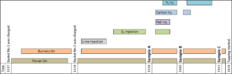
Typical operation example of EAF in Avesta under sampling campaign
Global (bulk) chemical composition
Some different parts of each slag sample were randomly chosen, crushed to powder and compacted onto borate plates. Thereafter, the composition of the samples was determined using X‐ray fluorescence spectroscopy. The results represent an average value of the chemical composition of the bulk of the EAF slag. In addition, optical emission spectroscopy (spark optical emission spectroscopy) was used to determine the global composition of the steel samples. The accuracy of the measurements was up to three decimal places.
Petrographical analysis
Petrography was initially performed using LOM. Thereafter, an SEM using backscattered electrons was done on seven samples using a Zeiss Ultra 55 field emission gun SEM. In addition, the SEM was equipped with an EDS analyser. To prepare specimens for electron microscopy, three slag fragments from different parts of one slag sample were collected and mounted in a conductive epoxy resin. Thereafter, the specimens were ground and polished. Lastly, the specimens were coated with a gold–palladium layer to make the surface more conductive. Then, SEM–EDS analysis was carried out using a working distance of 7–9 mm and an acceleration voltage of 20 kV. On average, spot microanalysis for every phase or particle, within one slag fragment, were repeated 8–10 times.
To confirm the existence of the observed phases, XRD analyses were performed on fine powdered samples using a Siemens XRD diffractometer D5000 instrument (Siemens Analytical X‐ray Instruments Inc., Madison, WI, USA). The diffraction peaks were measured using a 0·05° step scan and a scan speed of 2·5 s/step.
Results and discussion
Global slag composition (X‐ray fluorescence spectroscopy)
The measured values presenting the compositional range of the slag samples taken at different sampling moments are presented in Table 2. It shows only the major slag components (SiO2, MnO, Cr2O3, Al2O3, CaO, MgO, FeO and TiO2). Other components, which totally were <1 wt‐% of the slag, were neglected. The presented temperature values are the slag temperatures. It was assumed that the slag temperature is 50°C higher than the measured steel temperatures. This assumption was based on personal communication with operators and engineers at the meltshop. The slag temperature before tapping, in average, is 1756°C. Comparing this to the measured slag temperature at the same sampling moment during the production of the austenitic steel3 shows that, at the tapping, the slag in EAF duplex steelmaking is around 50–60°C warmer than that in EAF austenitic steelmaking. This is in agreement with that asserted in the introduction section.
Compositional evolution of bulk slag (in wt‐%), averaged temperature (in °C) and basicity (CaO/SiO2) of slag samples during different EAF process stages
*It was assumed that the slag temperature is 50°C higher than the measured steel temperatures.
Table 2 also shows the basicity of the slag in three different stages of the EAF process. The definition of the slag basicity is given by equation (1)

During the oxygen injection and before the FeSi injection, the Cr2O3 content is on its highest level (10–22 wt‐%). Durinck et al. 2 reported that, during the production of austenitic stainless steel and at the same sampling moment, the slag contains 10–16 wt‐% chromium oxide. This implies that, at this sampling moment, duplex steelmaking slags contain up to 25% more chromium oxide than austenitic steelmaking slags. This corresponds to that predicted in the section on ‘Introduction’.
As can be seen in Table 2, Cr2O3 content of the slags drops to considerably lower levels (3–9 wt‐%) after FeSi injection. Since the silicon has a greater affinity to oxygen, it can reduce the chromium oxide and revert back the chromium to the steel bath. The reduction of chromium oxide by silicon can be expressed by equation (2)
15

Typical elemental composition of steel bath, for major elements, at different EAF process stages (84142A–C), wt‐%
According to Table 2, the Cr2O3 content of the slag has its lowest level at the tapping stage (2–7 wt‐%). Since the furnace is a spout tapping furnace, it is reasonable to predict that the Cr2O3 content will decrease to even lower levels after tapping the furnace to the transport ladle. This is due to the mixing of the molten steel and slag during tapping, which improves the kinetics of the chromium oxide reduction. It is reported that the austenitic steelmaking slags contain 2–6 wt‐%Cr2O3 before the tapping.3 The samplings were carried out at the same furnace as the present study. This suggests that, at the final stage of the EAF steelmaking, austenitic and duplex steelmaking slags have similar Cr2O3 concentrations.
Table 2 shows that, in contrast to the FeO and MnO levels, the MgO level of the slag increases as the process proceeds. This is probably due to the dissolution of the MgO from the refractory of the furnace into the slag. The rate and the mechanisms of the dissolution of the MgO into the slag have previously been studied.16 However, the addition of dolomitic lime can reduce the chemical gradient between the slag and the refractory. This, in turn, can reduce the refractory wear. 17 17,18 Furthermore, Table 2 shows that the averaged basicity of the slag, after the FeSi injection, drops from an initial value of 1·44 to 1·40, which is due to the increase in SiO2. Thereafter, the basicity rises again to 1·48 due to the increase in the CaO. An explanation for this increase could be that, as the slag temperature rises from 1726 to 1756°C, the dissolution rate of undissolved CaO, which is in a dicalcium silicate form,16 increases. Undissolved CaO is mostly accumulated far from the centre of the furnace.19 Thus, by increasing the dissolution of the CaO in the slag, the slag in the centre region of the furnace becomes richer in CaO than before. Considering that the slag samples were taken from a region near the middle of the furnace, it is reasonable that the CaO content in the samples increases to some extent (2–3 wt‐%) with an increased temperature, as shown in Table 2.
Observations using SEM–EDS and LOM
Figure 3 shows a typical microstructure of slag samples. Besides a darker matrix, the main constituents of the slag samples are angular spinel particles, spherical metallic droplets and black voids. Apart from these phases and particles, which are common between austenitic stainless steel slags and duplex steel slags, some other phases and structures were observed in the duplex stainless steel slag samples. These also will be discussed in details in the following parts. The most important primarily precipitated phases presented in this study are listed as follows: magnesiochromite spinels (MgO.Cr2O3), calcium chromite (CaO.Cr2O3), perovskite (CaO.TiO2) and dicalcium silicate (2CaO.SiO2). In addition, the bulk slag matrix and some phases, which were precipitated during solidification of the slag samples, will also be discussed.
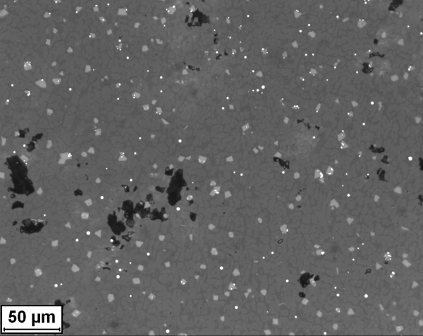
Optical microscopic image: typical microstructure of EAF slag samples (84167C)
Magnesiochromite spinels (MgO.Cr2O3)
While some of the samples contained spinels with dendritic structure (Fig. 4), angular shape spinels (Fig. 5) could be found in all the slag samples. These angular particles are normally unevenly distributed within the slag samples. The uneven distribution of these particles in the matrix phase can indicate that these particles have existed in the liquid slag at the process temperatures.
2
2,3 The precipitation and dissolution of the magnesiochromite spinels can be presented by equation (3). It should be considered that magnesiochromite spinel is not a stoichiometric compound.
2
2,3

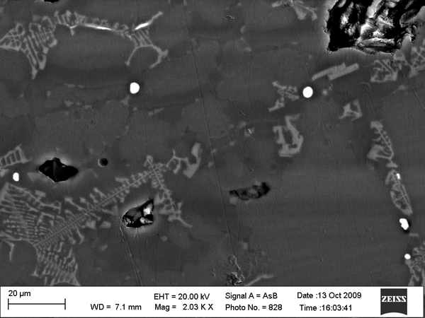
Backscattered electron image: dendritic structure in slag matrix (84167C)
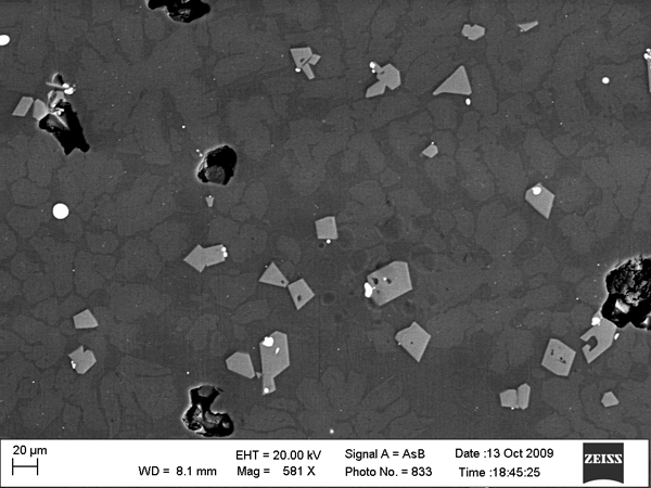
Backscattered electron image: angular shaped spinels (84142B)
In contrast to the angular spinels, the dendritic spinels evolve continuously during solidification and do not exist at process temperatures.
3
3,20 This is despite the fact that the chemical compositions of the dendritic and angular spinels are fairly similar. Table 4 shows the averaged composition of the large spinels (>15 μm) in a typical slag sample at three different stages of the process. The compositions are normalised to 100%, by considering the following major components: Cr, O, Mg, Al, Ti, Mn, Fe and Ca. Furthermore, oxygen is not included in the table owing to the lack of accuracy in determining the oxygen content by SEM–EDS. Although the compositional heterogeneities of the spinels from one and the same slag sample (Table 4), the angular shape and the composition of these particles correspond to the magnesiochromite spinels (MgO.Cr2O3).
2
2,3 These spinels are solid solutions with a chemical simplified formula of (Mg2+, Fe2+, Mn2+, Ti4+, Ca2+, Cr2+)(Cr3+, Fe3+, Al3+)2O4. The general formulation of the spinel is 
Averaged elemental composition of large spinel particles in three different sampling moments, wt‐%
*n represents the number of large spinels analysed in each sample.
†Numbers in parentheses indicate the averaged standard deviation of the analyses performed on a slag sample.
As Table 4 illustrates, the change in the spinel composition between the samples taken at different process stages (A, B and C) is not particularly large. However, while the MgO content increases continuously, the Cr2O3 content of the large spinels drops initially after FeSi injection. Thereafter, it rises again towards the end of melting process. This trend, which could be observed in most of the sampling heats, is not in agreement with the results reported by Durinck et al. 2 for austenitic stainless steel slags.
A few studies have been carried out to investigate the compositional dependence of the chromite spinels on the condition parameters.20,23 – 25 Despite the slag melt composition, several other parameters affect the spinel phase composition. Toppani and Libourel20 have shown that the content of different oxides within the spinel crystals is strongly influenced by the oxygen partial pressure and the temperature. Furthermore, the duration of the existence of the spinel particles in the slag also have an effect on their composition. As can been seen in Table 2, the total chromium oxide content of the B samples is significantly lower (3–9 wt‐%) than that of the A samples (10–22 wt‐%). The reduction in the total Cr2O3 content probably is the explanation behind the decrease in the chromium content of the spinels in B samples (than A samples). This is exactly the case for the iron content of the spinels, too. Unlike A and B samples, the global compositions of the B and C samples are fairly similar (Table 2). Thus, the impact of the slag melt composition on the differences in the spinel compositions of B and C samples cannot be large. On the other hand, the retention time of the spinels in the C samples has been, on average, longer than that of the B samples. Toppani and Libourel20 showed that chromium content may rise significantly by increasing the retention time of the spinel in the slag melt at high temperature. This may explain the slight increase in chromium content of the spinels at final stage of the process. In addition, it has been reported that the Cr2O3 concentration of the spinels increases with an increased temperature.20 However, a more detailed discussion of these complex influences on the spinel composition is beyond the scope of this paper.
Calcium chromite (CaO.Cr2O3)
In contrast to the magnesiochromite, which is a solid solution,
2
2,3 calcium chromite is a stoichiometric compound,
26
26,27 which could be observed in the slag samples taken before the FeSi addition (A samples). In these samples, the chromium oxide content is high (10–22 wt‐%), and the MgO content has its lowest level (3–4 wt‐%), as seen in Table 2. In addition, Fig. 6 shows calcium chromite crystals in the slag matrix. An averaged chemical composition of this phase in one slag sample can be seen in Table 5. The proportions of the chromium, calcium and oxygen atoms in the observed crystals strongly correspond to the stoichiometric calcium chromite phase. The result is in agreement with that reported by García‐Ramos et al.,28 who found that CaO.Cr2O3 crystals in the synthetic slags contain 10–20 wt‐%Cr2O3 and have a basicity equal to 2. Although they reported that by adding 5–15 wt‐%MgO to that slag, the only Cr‐containing compound found in the slag would be MgO.Cr2O3. However, the present authors believe that as equation (3) proceeds, the MgO level and, correspondingly, its activity in the slag decreases. Thereby, it will reduce the possibility of equation (3) to take place. At this step, unreacted Cr2O3 in the slag reacts with CaO and forms CaO.Cr2O3. This reaction is shown by equation (4)

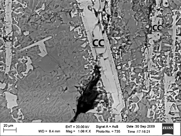
Backscattered electron image: calcium chromite crystals (84142B)
Averaged elemental composition of calcium chromite crystals analysed in sample 84147A, in comparison to stoichiometric composition of calcium chromite, wt‐%
Perovskite (CaO.TiO2)
Perovskite was observed in the samples with a higher slag basicity (>1·55). Table 6 presents an elemental composition range of this phase in a slag sample. As can be seen in Table 6, apart from Ca and Ti, perovskite crystals contain also noticeable amounts of other elements, especially Si. Zhang et al.
29 reported the general chemical formula of perovskite as (Ca, Mg, Al, Fe)(Ti, Al, Si)O3. Furthermore, the found crystals, in the present study, contained also low amounts of Cr and Mn. Figure 7 shows perovskite crystals in the slag, adjacent to magnesiochromite spinels. The observed crystals were often finer than magnesiochromite crystals, with a diameter of <10 μm. In addition, they could be found in lower amounts. These crystals, which are darker than magnesiochromite spinels, are also unevenly distributed in the slag matrix (Fig. 7). The size and the uneven distribution of these angular particles suggest that those were formed before solidification. Gho et al.
30 investigated the precipitation and growth of perovskite crystals in titanium bearing blast furnace slags. They suggested that perovskite is produced in the molten slag by the combination of Ca2+ and 
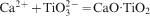
Backscattered electron image: perovskite crystals in comparison with magnesiochromite spinels (84147B)
Averaged elemental composition of perovskite crystals analysed in sample 84147B, wt‐%
Dicalcium silicate (2CaO.SiO2)
Dicalcium silicate was detected by SEM–EDS analyses in all the slag samples. The observed crystals contained high amounts of Ca, Si and O, which corresponds to calcium silicate phases. Table 7 shows a typical elemental composition of this phase in a slag sample. The composition is most consistent to dicalcium silicate (2CaO.SiO2). The microstructure of these particles, in most cases, unambiguously indicates that the crystals are formed after sampling. As can be seen in Fig. 8, the dicalcium silicate crystals have grown evenly and collided with each other, which have resulted in clear borders between the particles. However, in few cases, clustered and unevenly distributed dicalcium silicate crystal could be observed. These may correspond to primary formation of dicalcium silicate. In other words, crystals precipitated in the slag before sample collection. Figure 9 shows primary precipitated dicalcium silicate particles. No clear compositional difference could be distinguished between these two types of microstructures.
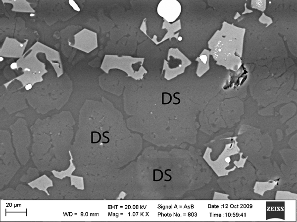
Backscattered electron image: dicalcium silicate crystals, precipitated during solidification (84147A)
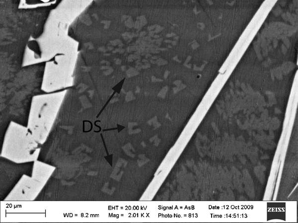
Backscattered electron image: primary dicalcium silicate crystals and clusters, existed in bulk slag before sampling (84142A)
Typical elemental composition of calcium silicate crystals detected in sample 84167C, wt‐%
Park et al. 26 calculated a phase diagram for an AOD slag with a very similar composition to the present EAF samples, especially sample A (before FeSi addition). More specifically, the studied slags contained 40–50 wt‐%CaO, 20–30 wt‐%SiO2, 10–15 wt‐%Cr2O3, 5–10wt‐%MnO and <5 wt‐%MgO. These data can be compared with the values presented in Table 2, for samples A. The calculations of Park et al. 26 showed that the slag contained dicalcium silicate phase at 1700°C. In addition, they could also detect primary precipitated dicalcium silicate phase in the slag samples using SEM–EDS. It is noteworthy that the slag samples were rapidly solidified by pouring them onto a water cooled copper plate. Park et al. 26 proposed the general chemical formula of [Ca2+, Mg2+, Mn2+]2SiO2. However, the authors could also detect Al, Ti and Cr, in very low amounts, in the analysed dicalcium silicate crystals (see Table 8).
Typical elemental composition of merwinite phase detected in the sample 84167C, wt‐%
Moreover, it is of interest to mention that some of the slag samples with a higher basicity (>1·6) disintegrated into a fine powder after cooling. The is due to the transformation of the monoclinic β‐dicalcium silicate to the orthorhombic γ. This dicalcium silicate crystallographic transformation is accompanied with an increase in volume, which in turn results in disintegration.32 The extent of the volume increase is up to 11%.18
Matrix phase
Qualitatively expressed, the main constituent of the bulk slag, for a duplex stainless steel slag, is the molten part of the slag. In Fig. 10, this phase can be seen as a grey vitreous matrix. This in agreement with that observed and reported by Mostafaee et al. 3 for AISI 304L stainless steel. During the solidification procedure, this part of the bulk slag, which is in liquid state at sampling temperatures, 2 2,3 can completely or partially transform into an amorphous structure depending on the cooling rate.11 The chemical composition of the glassy matrix was determined to be, more or less, similar to the global chemical composition of the bulk slag. 3 3,10 However, the chromium oxide content in the slag matrix phase was always found to be several weight per cent lower than that in the bulk slag. This is due to the concentration of chromium in the chromite crystals. 2 2,3
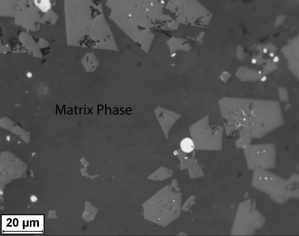
Optical microscopic image: overview of glassy slag matrix phase (84147A)
Merwinite (3CaO.MgO.2SiO2)
A phase, darker than matrix, which is mainly composed of Ca, Si, Mg and O, was also detected in all samples, except for samples A. This phase is illustrated in Fig. 11. An averaged composition of this phase is shown in Table 8. The composition is fairly well consistent to merwinite (3CaO.MgO.2SiO2). Since the melting temperature of the merwinite is ∼1575°C,33 it is reasonable to believe that this phase does not exist in the bulk slag at the sampling moments (T⩾1590°C). Eriksson and Björkman18 reported that, with the increasing MgO content of the stainless steel slag, the merwinite phase can form during cooling procedure. This can probably explain the absence of the merwinite crystals in the A samples. These samples contain less amount of MgO than other samples, as presented in Table 2. However, the formation and the growth of this phase have also certainly been restricted by the rapid solidification.
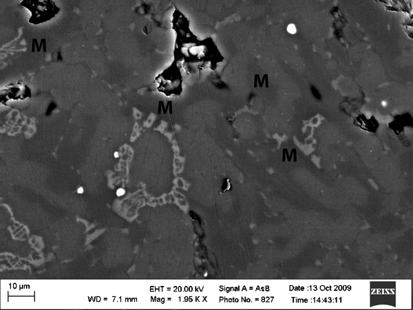
Backscattered electron image: merwinite phase which is darker than slag matrix, precipitated during cooling (84167C)
X‐ray diffraction analysis
The XRD pattern of a slag sample taken before FeSi injection (sample A), is shown in Fig. 12. Magnesiochromite and calcium chromite characteristic peaks were detected. This verifies the SEM–EDS determinations, which also have revealed the existence of these phases. Figure 13 illustrates the diffractogram for a slag sample taken before tapping (sample C). Here, the sample definitely contains magnesiochromite and dicalcium silicate. As can be seen in Fig. 12, the diffractogram shows a broader baseline in comparison to Fig. 13. The probable reason for the broad baseline is due to a more extensive glassy matrix. Depending upon the rate of the cooling, the slag samples contain an amorphous matrix to different extents. Figure 13 shows sharp narrow diffraction peaks together with a narrower baseline. In this case, it is most probable that the existing silicate have been crystallised to a larger extent. This can be confirmed by the fact that this slag sample underwent a self‐disintegration after the solidification. This was probably due to the transformation of the monoclinic β‐dicalcium silicate to the orthorhombic γ.32 It is remarkable that the peaks (Fig. 13
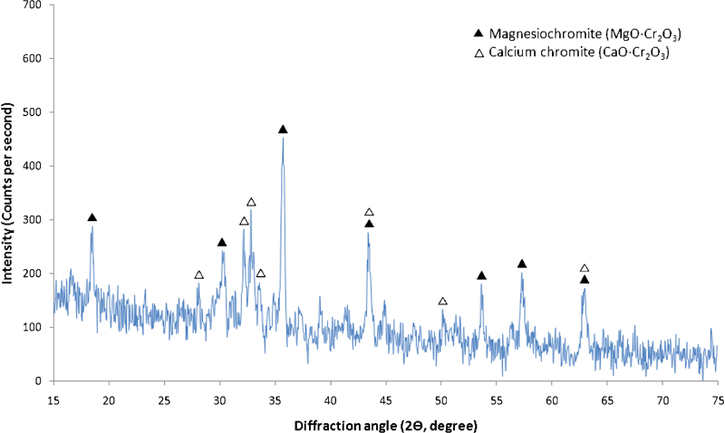
X‐ray diffraction spectrum of slag sample taken before FeSi injection (84197A)
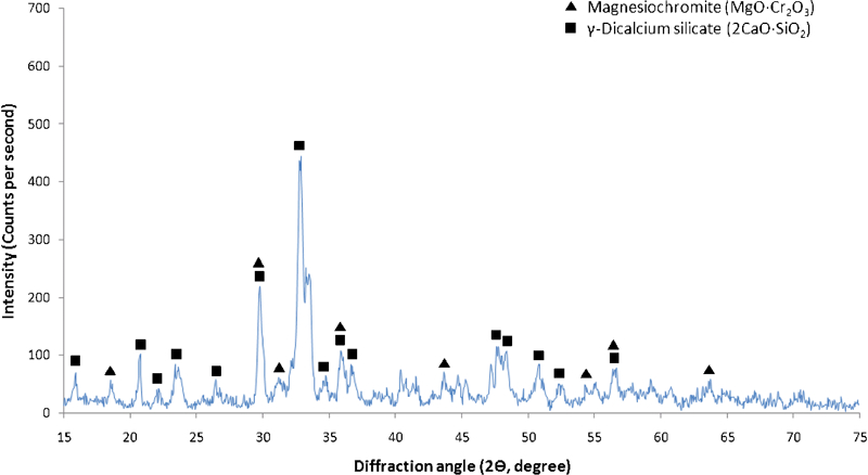
X‐ray diffraction spectrum of slag sample taken before tapping (84147C)
Concluding discussion
The results of the petrographical analyses and observations are summarised in Table 9. The illustrated phases are primary precipitated phases. More specifically, the phases and particles which exist in the bulk slag before samplings. Magnesiochromite spinels, metallic droplets and a glassy matrix could be found at all sampling stages. Calcium chromite could be detected just before FeSi addition. In this stage, which is at the final part of the O2 injection and before FeSi injection (Fig. 2), the Cr2O3 content of the bulk slag has its highest level (10–22 wt‐%). At the same time, the MgO content was found to be on its lowest level (3–4 wt‐%). In this condition, the driving force for further reactions between MgO and Cr2O3 is too low; thus, the unreacted Cr2O3 in the slag reacts with CaO and forms CaO.Cr2O3. After FeSi addition, the Cr2O3 content drops to much lower levels (3–9 wt‐%) due to the reduction of chromium oxide by silicon (equation (2)). Thereby, the SiO2 level rises to 31–36 wt‐%, as seen in Table 2. At this stage, the only Cr2O3—rich phase within the slag is magnesiochromite. After FeSi injection into the EAF and during the refining period, the composition and the basicity of the slag in the EAF duplex and EAF stainless steelmaking are fairly similar. 2 2,3 This probably indicate that, during the refining period, the basic condition for the utilisation of an EAF foaming slag praxis, in both austenitic and duplex stainless steel cases, is the same.
Summary of phases and particles identified in slag samples at different EAF process stages*
*X: phase exists in the slag; (–): phase does not exist in the slag.
†Phase observed in the slags with a basicity higher than 1·55.
‡It is possible that a part of or the whole phase has precipitated during solidification.
Perovskite (CaO.TiO2) could be observed in the samples with a higher basicity (>1·55), regardless of the sampling stage. In addition, the observed perovskite crystals contained noticeable amounts of silicon in their structure (see Table 6). Thus, it seems likely that the slag basicity has a decisive influence on the precipitation and growth of perovskite crystals. More specifically, the crystallisation of the CaO.TiO2 phase is reduced with decreased slag basicity.
Dicalcium silicate (2CaO.SiO2) could be found, in large amounts, in all the slag samples taken at any process stage. However, no straightforward method for distinguishing between primary and secondary precipitated dicalcium silicate could be found. This problem clearly points out that, for freezing the high temperature slag microstructure, a more rapid cooling procedure is required. For example, the slag samples can be more rapidly solidified by pouring them onto a water cooled copper plate.26 The present authors also conclude that it is absolutely useful to take slag samples also at other EAF process stages for a more thorough and detailed investigation of microstructural evolution of slag. For instance, by taking a sample from the slag, at the end of the carbon injection stage, the influence of the carbon addition on the solid phases could be studied. However, within the sampling period for this study, taking slag samples at more process stages involved practical difficulties.
Generally, as the melting and refining stages proceeds, the temperature of the slag increases (Table 2), and the amount of solid phases and particles in the slag decreases. However, the character, amount and the composition of the solid phases and liquid part of the slag are also dependent on other parameters, such as the global composition of the bulk slag, the slag basicity and the oxygen partial pressure at different stages of EAF process. Thus, it can be concluded that a rigorous thermodynamic study could be instrumental to investigate the effects of changing conditions on the slag phases in EAF duplex stainless steel production. Moreover, to fully understand the interaction between the phases within the slag, the thermodynamic determinations seem indispensable.
Conclusions
Based on the observational and petrographical study of seven EAF duplex stainless steel heats (21·5–22·5wt‐%Cr, 1·6–5·7 wt‐%Ni and 0·3–3·2 wt‐%Mo), microstructural evolution of the slag in different EAF process stages was investigated. For this purpose, microscopic observations and compositional determinations were used to study and characterise the high temperature microstructure of the slag phases. Slag samplings were performed at three different stages for each heat, namely, before ferrosilicon (FeSi) addition, after FeSi addition and before tapping. The taken samples were analysed by LOM and SEM–EDS. In addition, XRD analysis was performed to verify the results from petrographical analyses. The most important conclusions from this study may be summarised as follows.
At all sampled process stages, the slag consists of magnesiochromite spinels, metallic droplets and liquid oxides.
Before FeSi addition, the slag also contains solid stoichiometric calcium chromite, where the chromium oxide content is high (10–22 wt‐%) and the MgO content has its lowest level (3–4 wt‐%).
Depending on the slag basicity, the slag may contain perovskite and/or dicalcium silicate. More specifically, the slag samples with a basicity higher than 1·55 were found to contain perovskite crystals (CaO.TiO2).
Before the tapping stage, the composition and the basicity of the slag in the EAF duplex and EAF stainless steelmaking are similar. This can imply that, at this stage, the basic condition for the utilisation of an EAF slag foaming praxis, in both austenitic and duplex stainless steel cases, is the same. On the contrary, before FeSi injection the Cr2O3 level of the duplex steelmaking slag is ∼25% higher than that for the austenitic steelmaking slags. This suggests a higher amount of second phase precipitates and thereby a higher apparent viscosity for the EAF duplex steelmaking slags.
An improved cooling procedure is required for a more rapid solidification of the high temperature slag microstructure of the samples.
A systematic thermodynamic study, for determining the amounts of different solid phases in the bulk slag, is suggested. Computational thermodynamic studies are also required to investigate the effects of changing conditions, such as slag composition, temperature and the slag basicity, on the solid phases within the slag in EAF duplex stainless steel production.
Footnotes
Acknowledgements
The authors are grateful to the Swedish Energy Agency (Energimyndigheten) and the Swedish Steel Producers Association (Jernkontoret, project no. JK23028) for financial support. The authors also wish to thank Outokumpu Stainless Avesta (Avesta, Sweden) and its personnel. The EAF operators and engineers at Outokumpu are specially acknowledged for assistance in performing plant trails and in determining the global chemical composition of the slag samples. Furthermore, the authors want to thank Mr Jyrki Pitkälä (Outokumpu), Mr Joakim Andersson (Outokumpu) and Mr Marcel Magnusson (Swerea MEFOS, Luleå, Sweden) for help during plant trails and for discussions regarding practical issues. Moreover, many thanks are given to Avesta Research Centre (Avesta, Sweden), especially Mrs Eva Engstedt for her assistance in microscopic analyses.