
Abstract
The need to automate welding processes in the shipbuilding sector is described, highlighting specific weld configurations and mechanised solutions. Some issues related to steel product supply into this industry sector are described highlighting specifically the material geometry requirements and their effects on automations are also discussed.
Introduction
In the continuing need to reduce costs and improve productivity in the shipbuilding industry there is a drive in Western Europe to introduce more automated processes into the production flow path. The main area for automation is currently in the welding operations. As there is a move to building higher value added vessels with enhanced quality requirements, the application of automation is economically significant. In some regions skill shortages are being seen, and the use of automation is a possible option to partly resolve this issue.
In a typical larger scale shipyard the primary welding is carried out at a panel line (see Fig. 1), with the main welding components listed under the two situations shown in Table 1.
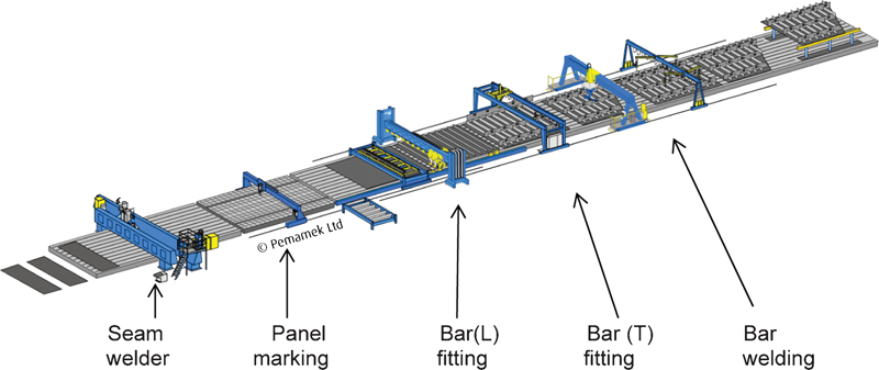
Component parts of panel line
Main welding components in panel lines
Panel line 1 is typical of the design concept that has been in place for many years, but the lower number workstations shown in panel line 2 are now a viable option.
Quite clearly there are variations of the two examples shown, for example, a turnover device or a panel rotation station could be included depending on the specific needs of individual shipyards. However, it is important at this stage to establish where automated welding processes could be used as an aid to productivity and quality.
Seam welding
Seam welding is carried out by a seamer, an example of which is shown in Fig. 2. These stations can vary in length for a few metres up to 22 m, and is a function of the layout of the shipyard involved. Within BAE Systems in the UK the seamers are 13 m long.

Seam welding installation in shipyard panel line
Primarily they weld from one side only, as generally there is a reluctance to turn panels unless absolutely necessary as it can create a counter flow situation on the line.
Seam welders can be fitted with automatic seam tracking devices, which also incorporate height sensors. The installation at the Govan yard of BAE Systems is a non-contact laser probe which incorporates a megapixel camera and sensor electronics capable of analysing 25 full frames per second. It is also capable of catering for tack welds that have been laid down when the plates were brought together. As all other aspects of the welding operation are preset (volts/amps/travel speed/wire feed speed) there is no real need for the operator to monitor the process. However, this also revolves around having welding equipment that is reliable and stable. In the case of the two BAE Systems yards in the UK, new power sources were installed to give this level of control and confidence.
One issue on seamers is seam end cracking which is a function of the tensile stresses built up towards the end of the seam. The crack which is generated is a longitudinal centreline crack running in the direction of welding. It is normally ∼65 mm long and starts 75 mm in from the end of the plate. This can be virtually eliminated by putting a customised run off plate onto the end of the panel. This design was verified using an FEM study.1 This approach is in contrast to that of some Japanese yards which utilise an automatic gouging and welding process at the end of the panel, covering the last 200 mm.
Double sided welding can be carried out on a seamer, by turning the panel over on a turnover device using extended arms and then feeding the panel back through the seamer. The issues here are related to having enough length behind the seamer to allow the whole panel to be moved back through, plus it is a counterflow movement, as highlighted earlier.
The seam welding process uses predominantly the submerged arc welding (SAW) process, and within that, there are a number of options in how the process can be operated. For example, a high deposition filling run could be carried out using three electrode wires. One of the issues created by seam welding is related to heat input, and in the case of the simple square edge preparation, the dilution from the parent plate.
The main issue is related to the heat affected zone (HAZ) toughness of the weld. Basically this is the volume of the parent plate which has not been melted by the arc but is beside it and has undergone thermal cycling. In a number of situations the parent plate toughness can be reduced by 50% depending on the heat input it has been subjected to. The area termed as the HAZ is outlined in Fig. 3. Also shown in this figure is some centreline segregation. Although specifications do not reflect this, the parent plate used for this type of application should have double the toughness of the heat affected zone minimum toughness. Alternatively the use of titanium in the plate has the effect of restricting HAZ grain growth due to the presence of titanium nitrides in the microstructure.2 An example of a titanium nitride particle is shown in Fig. 4, where the steel was quenched from 1400°C. This clearly demonstrates the high temperature stability of these particles.
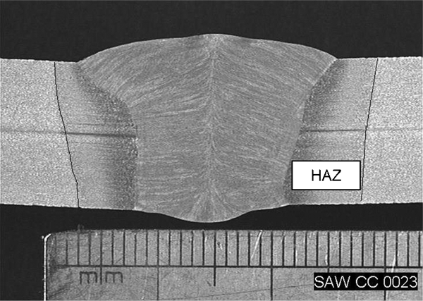
Cross-section macrograph of single sided seamer weld with HAZ outlined
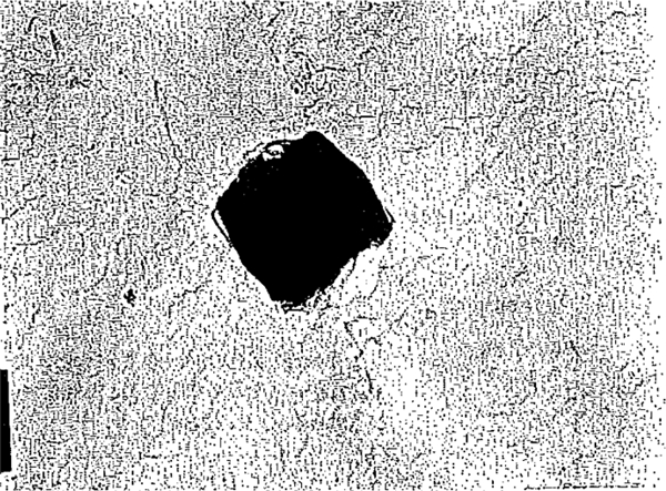
Titanium nitride particle in steel quenched from 1400°C (Ref. 3)
Quite clearly for this higher heat input automated process there is a need to ensure that the optimum steel plate chemistry and mechanical properties are considered as being a key component of the total process.
In addition to using SAW as the welding process it is perfectly feasible to use metal inert gas (MIG) as an alternative welding process on a seam welding machine. This is how aluminium is welded on a seamer.
For carbon steels, there are some high penetration solid wire processes available which will match SAW for a single sided single pass with a square edge preparation. This specific process capability can be found in a multifeature system containing processes such as an invertor power source with highly dynamic actual value regulation, a concentrated welding arc, and a higher plasma pressure in the welding arc, which can lead to the creation of a smaller heat affected zone/less distortion/a reduction in the loss of parent plate toughness in the HAZ.
Over the last few years the seamer automatic welding process has undergone a number of changes which will increase the flexiblilty of the process. One process that has received a lot of attention in this area is the application of hybrid laser arc welding. For thin plate this process significantly reduces thin plate distortion and increases productivity. It is now a routine process in some European shipyards.
Irrespective of which welding process is used in this area, there is a need to maintain good flatness of the plates. Variations in flatness can either lead to additional preparation time or, variations in the extent of weld penetration. This is a particular issue with thin plates, i.e. <8 mm thick.
Butt welding
The main drawback of the SAW process is that it can really only be used in the downhand position, i.e. with the electrode pointing vertically downwards into the flux covering. However, there are still substantial welded lengths in ship structures where butt welds can be carried out automatically, despite not being suitable for SAW. To meet these specific requirements, track mounted welding machines can be put in place. This allows multipositional welding to be carried out, even in the overhead position. Work carried out a number of years ago4 showed that using this welding process in the horizontal position had highly significant effect in reducing the welding defects detected by radiography.
This type of equipment can be fitted with a cutting torch to allow a weld prep to be cut highly accurately, before fit up/welding. The overall production efficiency of the equipment is questionable at 4 and 5 mm thick where the set up time is the dominant factor. In multipass welds the efficiency of this process is unquestionable. However, on an early study5 of this process claimed a 72% reduction in welding time against the previous process.
This technology has also been applied to the construction of nuclear submarines.
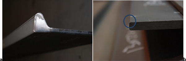
Overall the process only requires minor adjustment from time to time by the welder. From an ergonomic viewpoint this equipment has significant benefits. An example is shown in Fig. 5a of the bottom shell butt welding being carried out with a track mounted welding oscillator. The finished weld is shown in Fig. 5b .
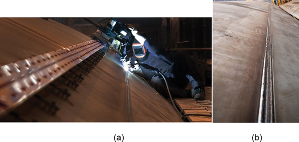
a mechanised butt weld using track mounted welding oscillator and b finished weld
The standard of the weld is generally defect free, and it requires almost no surface rectification.
This is a highly flexible process which can be used in any welding position including the overhead position.5
Fillet welding
As in the case of the seamer, the fillet welding process where bars are welded to plate, creates automation options from within the existing welding processes. In some cases, fillet welds can and are produced by the SAW process. In the production of welded T beams, the SAW process is used to double side weld the web to the flange. Many of the T beams call for slightly larger fillet sizes and the SAW can do this in one pass where it could take the MIG process up to three passes to get the correct fillet size.
Within shipyards the predominant process is MIG welding. This can use any of the following wires: flux cored, metal cored and sold. All three wires types can be used with mechanised processes.
One of the misconceptions of welding automation is that it is an expensive investment. That is not strictly the case. There are some very well designed and multifunctional fillet welding machines on the market. These can be in the form of cars or buggies, where the welding head is transported by a robust motorised transporter which can be either battery powered or via a supply cable. The buggies can be programmed to do intermittent welding and their speed and direction of travel can be altered easily. At under £4000 each, these are a sound investment even in some of the smaller shipyards. They can also be used to weld a fillet vertically up, as a number of them have a magnetic system which keeps the transporter in contact with the steel plate.
One area in fillet welding that has the potential to be an issue, as the overall processes become more controlled and seek higher output, is the area of the toe of the offset bulb plates (OBP). An example of the bulb profile is shown in Fig. 6a .
a bulb profile and b rounded profile on toe of bulb
If the bulb is rolled as a single item, and not a double item to be slit longitudinally after rolling, then there is strong tendency to have one edge very square and the other one is radiused. In theory there would be justification in altering the fillet sizes from side to side. The condition on the toe of the bar is illustrated in Fig. 6b .
Automated fillet welding installations (not robotic) are present in a number of shipyards and there is an example quoted6 of one which has five double sided welding heads using a twin arc process. The welding speed in this case is 1·2 m min−1. However, this process would not be suited to thin plate as the potential heat build-up of the multiple arcs would lead to distortion. This is a gantry based system. Another gantry based system utilises four welding heads simultaneously to weld egg box constructions predominantly in the double bottoms of larger vessels. Again this high heat input configuration would not be suitable for thinner materials. There are a number of variations of automated welding processes around a similar theme.
Optimum fillet welding conditions have been developed for the vertically up position using an artificial neural network (ANN) approach.7 Currently work8 is in place to extend this initial study to cover the multi variable do the same on the downhand welding position.
Robotic welding
The uptake in robotic welding in the UK shipyards has been very low. One of the most productive areas to install a robotic welding cell would be at the end of a panel line, where the entire bar welding could be carried out in one single stage. In addition, to carry out the welding, a weld sequence can be overlaid on top of the programme. This would effectively counter the potential for the structure to distort, which is particularly critical with 4 and 5 mm thick plate panels. The justification for using a robotic cell to do fillet welding at the end of a panel line would be based on arc time which is the time over which an arc has been physically struck. For a welder using the semiautomatic flux cored process the arc time would be ∼32% over a full shift period. In comparison, a robot would be expected to have an arc time of at least 85%, i.e. just under three times as much as the semiautomatic process.
An integral part of the robotic welding process of panels was that the programmed data were normally downloaded from the company CAD system. However, in recent years a number of companies have been developing vision based systems, which means there is no reliance on the CAD system. This is a process by which the complete panel is laser scanned and the scan data are converted to a welding programme for the robot. With the vision system only the bars that are actually on the panel are welded. For example, if a bar was missing, the CAD based system would require manual intervention to remove the bar from the programme. The vision based system only welds what the scanner has actually recorded. An example of an assembly being welded which incorporated the vision welding process is shown in Figure 7. In theory, the vision based systems should be more efficient than the CAD based systems.
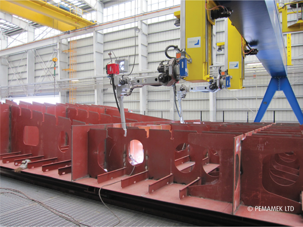
Example of panel being welded after having been scanned by vision process
Expectations of exactly what robotic systems can achieve can be raised artificially and there will normally always be a proportion of hand welding to be done once robotic welding has been completed.
What does this mean to steel maker and supplier?
The most critical aspect in the supply chain for an automated welding process is consistency of material supply. This means consistency in the product geometry, i.e. for plate and flat bar, flatness and thickness, and in the case of bulb bar the longitudinal bow and straightness are key elements, along with the toe of the bar profile described earlier. Even with good flatness, the issue of residual stress in plates is a very significant factor when thin plate (4–6 mm) is being used. During plate processing the residual stress can be released in the most unpredictable ways and the outcome is that this will create rework to rectify it.
Consistency of mechanical properties has been improved significantly, mainly driven by offshore requirements, but in automated processes such as high heat input high dilution seam welding, potential loss in toughness in the HAZ has to be compensated for. There is also an unrealistic element within the toughness specifications for plate which does not allow for the effects of welding on HAZ toughness. There is now a very good case to carry out a review on the requirements for ship plate and bar.
Footnotes
Acknowledgements
The author wishes to thank Pemamaek Oy for the supply of Figs. 1 and ![]() . In addition, it should be noted that the views expressed by the author may not necessarily be those of BAE Systems.
. In addition, it should be noted that the views expressed by the author may not necessarily be those of BAE Systems.