
Abstract

Introduction
The Queen Elizabeth Class Aircraft Carriers is the largest UK Royal Navy contract ever built. It was developed in response to having an aging fleet of three aircraft carriers, which were in recent service but, through age and design, had progressively limited capabilities compared to those of other navies such as the USA and France.
HMS Ark Royal went into service in 1985 having been built at the Swan Hunter Yard on Tyneside. In 2011, it was decommissioned. HMS Invincible went into service in 1980 having been built at Vickers Shipbuilding and Engineering at Barrow in Furness. Decommissioning followed in 2005. The third vessel HMS Illustrious was commissioned in 1982 and decommissioned in 2014, having been built at Swan Hunter on Tyneside. These light aircraft carriers had lifespans of between 22 and 26 years. The QEC carriers have been designed to have lifespans of ∼50 years. However, this figure has been the subject of some debate.
The two vessels are HMS Queen Elizabeth and HMS Prince of Wales. BAE Systems and Babcock International Marine were the two Tier One contractors and were supported on the hull build by the following Tier Two contractors: Cammell Laird on the River Mersey and A and P Tyne on Tyneside. The detail of the work carried out will be described later.
Main design features and build
The primary conception of the two vessels was as a joint strike asset. However, the principal driver to the QEC design was the capability to deliver offensive air power at the medium scale. A number of potential options existed for the jets to be adopted including the short takeoff and landing variant.
The main features are as follows: overall length of 280 m beam at waterline of 39 m width at deck level of 70 m height of 56 m draught of 11 m a deep displacement of 65 600 tonnes at start of life.
There are nine decks constructed from 19 transverse water tight sections. The two significant decks are the flight deck and the hanger deck, which were subject to significant debate on which material was to be used. The philosopy that underpins the QEC design is that the vessels are being built to essentially commercial design standards with naval engineering standards only being incorporated where it was deemed to be absolutely necessary. In general terms, the structure is an all steel construction using a mixture of steel plate, welded T bars and offset bulb plates.
Thereafter, a ‘Super Block ‘ build strategy was adopted, which saw the lower hull blocks built and preoutfitted at BAE facilities in Glasgow and Portsmouth and Babcock International facilities at Appledore and Rosyth. This was based on matching the UK build facilities to achieve the desired in-service dates, as no one facility could meet the overall project demands. One of the super blocks is shown in Fig. 1. This was built as two blocks and one block was built in the left hand bay, while the other part was built in the right hand side bay. After block completion, the left hand block was moved into line with the block in the right hand bay, and the two blocks were linked together to form a block weighing almost 11,300 tonnes. However, it was necessary to utilise the capabilities of ‘tier two’ shipyards at Cammell Laird on Merseyside and A and P Tyne on Tyneside to fabricate upper block parts of the structure, which included the flight deck. All block components were barged to Babcock International Rosyth where wholeship integration took place and is shown in Fig. 2. This figure shows the first QEC vessel well through the build cycle. The forward island has just been loaded onto the deck in the ringed area, and some of the aft decking has still to be lifted into place. Key to this work was the specifically built Goliath crane, which is the blue structure straddling the dock.
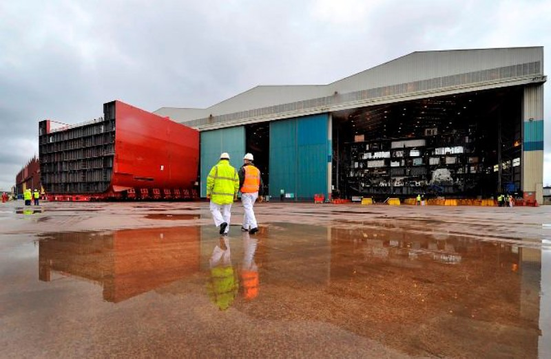
Superblock construction at BAE Systems Govan yard of lower block 4
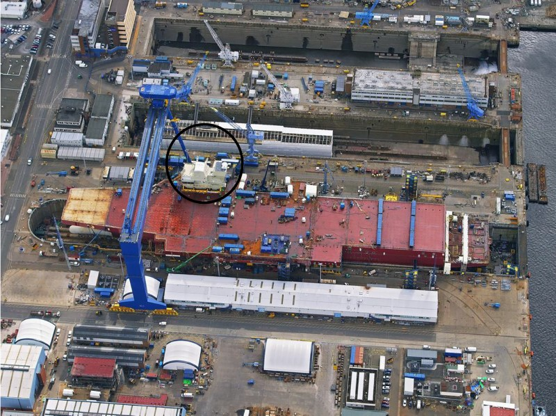
First QEC vessel in integration dock at Rosyth, with forward island (ringed) being put in place
The first QEC vessel build configuration is shown in Fig. 3. However, this changed for the second vessel as the BAE Systems yard at Portsmouth was closed part way through the build with the remaining work being undertaken at BAE Systems Glasgow yards.
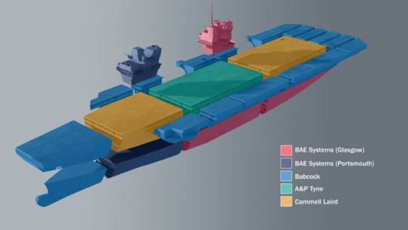
Apportionment of structural build for first QEC vessel
Some design features from commercial build concepts have been adopted. For example, the bulbous bow, fore and aft shoulders and a parallel middle body create a hullform of a balanced design, which creates minimum powering requirements at both cruise and maximum speed. A transom flap has also been incorporated, which reduces resistance and therefore reduces fuel consumption. The bulbous bow configuration is shown in Fig. 4, where the bows for each ship can be seen side by side. These are common on many commercial vessels, and at one point, shipbuilders were considering that these could be produced from glass reinforced plastic (GRP), using a bolt on concept.
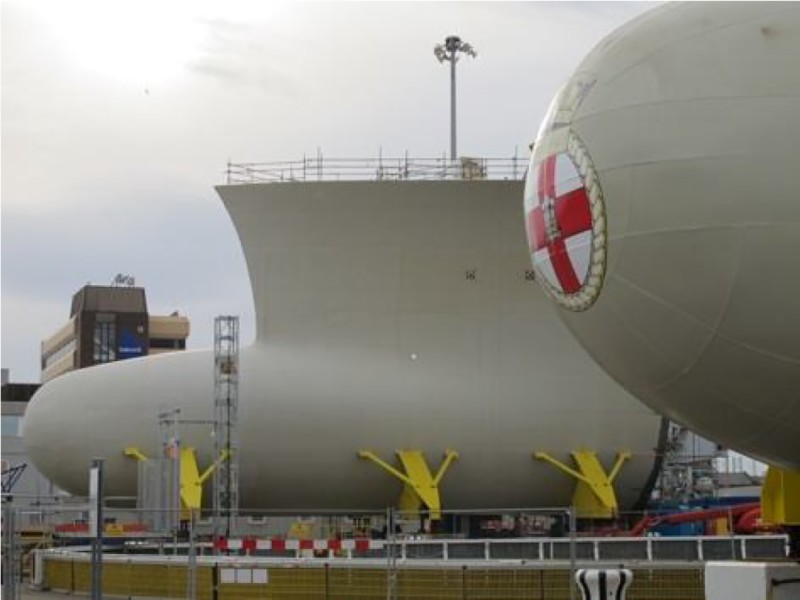
Bulbous bows for QEC contract
Within the design is the twin island arrangement on the flight deck, which offers a number of significant advantages, one of the most critical being, that if one island was incapable of functioning, for any reason, then the remaining island was capable of handling the bulk of the functionality.
These two vessels will be the first Royal Navy ships to be fitted with an integrated full electric propulsion system, although the type 45 destroyer programme used a significant number of elements of it. To meet the power demands, two Rolls Royce gas turbine alternators plus four Wärtsilä supplied diesel generators were used. This capability provides power for both propulsion and ship's services.
Materials for QEC
Hull steel
The bulk of the vessel structure is Lloyds DH36 steel. This grade of steel has been progressively displacing Lloyds D and Lloyds A grades, which were commonly used in naval vessels. This move has created an element of light weighting of vessels due to the use of a higher strength steel. As a result, the use of DH36 steel was not considered as a problem to the various build yards, as all had extensive experience in its use. However, the flight deck and the hanger deck were subject to a number of grade iterations, and it was envisaged that some benefits could be obtained by the possible use of higher strength steel on these two decks. The base case had been previously set as being Lloyds Grade EH36. Some of the alternatives were EH55, EH46 and EH42 grades. An evaluation centred on a number of issues, such as availability of the steel grade, weldability of the steel grade, cost of the steel grade and potential tonnage reduction. The outcome was that EH46 was chosen. There was a good track record of its use in the offshore sector, and there were a number of potential suppliers within the UK and Europe.
1
Within its grade scope, EH46 can be supplied in at least three processing forms: thermomechanically controlled processed (TMCP) quench and tempered (Q and T) thermomechanically controlled processed and accelerated cooled (TMCP and AC).
The TMCP route was selected for this contract as it created less weldability issues within a shipyard than Q and T. In addition, the enhanced toughness generated by the accelerated cooling for the last option was not required, and the toughness would be met by the TMCP route. There were also cost benefits from opting for the TMCP over the other two options. It was also established that the potential weight reduction generated from choosing EH46 led to an overall cost reduction for the flight deck and the hanger decks. As part of this contract, the customer (MOD) required that the weld metal toughness be tested at the same temperature as the parent plate toughness. This was different from the requirements of commercial vessels and more stringent. This requirement was for all steel grades used in the QEC build. Table 1 shows an early option at 20 mm thick, which was based on linepipe chemistry, using nickel and copper, in addition to the niobium and vanadium microalloys. The 35 mm thick option from Mill A was the typical chemistry used on this contract. It is a Nb–V microalloyed steel. The toughness shown here was further enhanced by adopting a lower sulphur practice and also calcium treating the steel. This created an average toughness of 130 J. A proportion of the steel had to satisfy through thickness reduction in area requirements of 35%, and this was consistently met by ensuring that the sulphur was < 0.003%. In that case, the benefits to toughness were a further 60% improvement. In addition, the use of the TMCP reduced the level of anisotropy within the plates, which is critical to toughness.
Chemical analysis (wt%) of some EH46 options
The last chemistry is from a TMCP-AC process route where the exceptionally fine microstructure has resulted in exceptional toughness. Technically, that could be a favoured option as a steel would be used, which could respond positively to high heat input welding. However, the typical properties also met the requirements, and it was considered that it would meet the heat affected zone toughness even when high heat input welding was used. This was seen as a value judgement as the TMCP-AC material was more expensive.
Pipe systems
There were four main materials used for the pipe systems on QEC, and they mostly followed the criteria used on commercial vessels. Carbon steel, stainless steel, copper nickel (80/20) and GRP were the materials used. The non-metallic GRP was mainly used in the ballast tank systems as it is known from commercial experience that its through life capability is significantly greater than than that of carbon steel and it is almost maintenance free. An example of GRP pipework in position is shown in Fig. 5. When converting for steel pipework to GRP pipework, the main difference is that the alignment for GRP has to be more accurate than for steel. Steel could be manoeuvred into position, but doing that with GRP can lead to flange cracking.
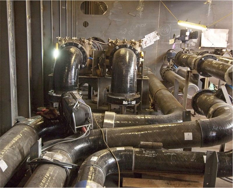
Example of GRP pipework
Not all the pipe systems were welded, and a process that involved mechanical coupling was used. This process has been designed to replace the need for flanging, welding and pipe threading. This is a high security fire protected system. It has a unique internal fire sleeve and double casing design, and it meets the naval ship requirements for shock and fire.
The net effect of the coupling systems and GRP is a reduction in the amount of pipe welding required.
Propulsion system
Some very large items are involved in the propulsion system, which has twin propellers. Shown in Fig. 6 is one of the propellers, which is manufactured in a nickel aluminium bronze. Each propeller weighs ∼33 tonnes and are of an adjustable bolted propeller design, which allows the most efficient blade matching for optimum efficiency while simplifying installation. It uses a hollow hub with five blades bolted from the inside. Slotted holes in the hub allow the blade pitch angle to be adjusted in service to compensate for variations in hull resistance through life.
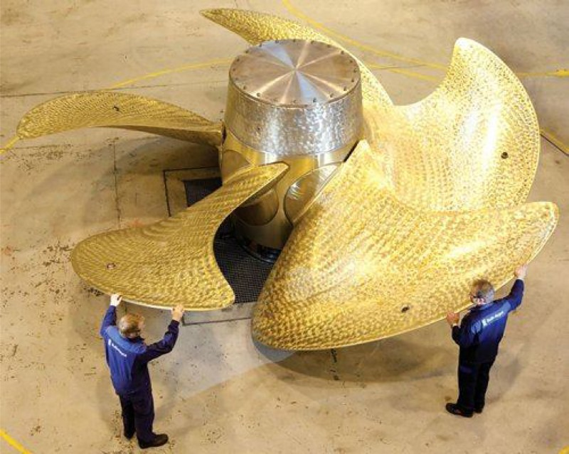
One of propellers for QEC
Supporting the propulsion shaft are two ‘A’ frames. The larger of the two is ∼130 tonnes, and the smaller is ∼90 tonnes. They can both be seen in Fig. 7. Both were produced from castings, and the grade was what is termed Lloyds Grade A (special). This basically meant there was a toughness requirement on the material. Dimensional control of the casting is critical, as minor differences in the shaft alignment going through the A frames can lead to later life issues such as vibration.
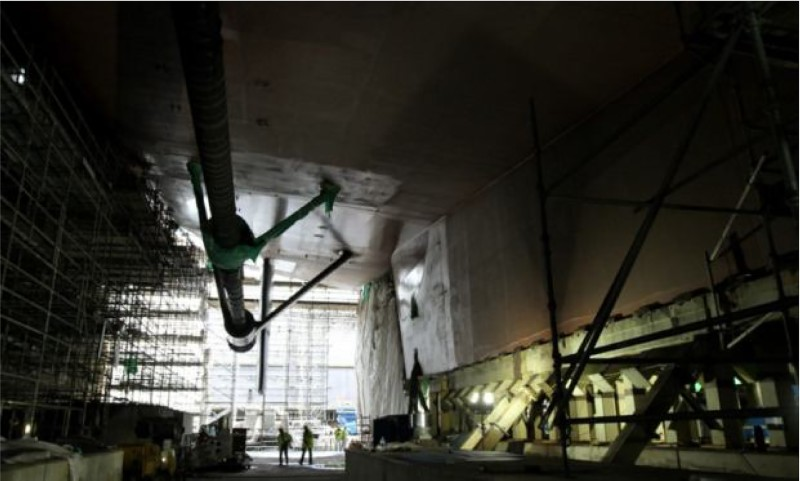
Frames supporting propulsion system beneath external hull
Welding
As EH46 was a new grade to most of the build yards, a welding group was set up to evaluate each yard's capability to weld EH46 using submerged arc welding, manual metal arc and flux cored arc welding. These were the main processes used at each of the yards, although very little manual metal arc was used. All yards were issued with steel from the same plate, but the choice of welding consumables was left to each yard.
Initially, there were some variations in the success rate, but the welding group acted as a highly effective ‘learner’ for each yard. For completeness, fracture toughness testing was carried out to enhance the Charpy toughness data that were generated. This was not a contractual requirement, but it created a greater degree of confidence in the process being used, rather than solely rely on Charpy toughness data.
The situation regarding welding consumable selection for DH36 grade was left to each yard, too, and the responsibility for getting the Classification Society approval was theirs. Most yards had existing DH36 weld procedures in place, as that grade of steel is very common in naval contracts and is growing in popularity with commercial builds.
During the contract, some additions were made to the welding consumables. One specific example was to use a flux cored wire under flux in the submerged arc welding process instead of solid wire. This move was highly beneficial as toughness was not an issue, deposition rate was higher, price was lower and, overall, there was a 34% saving in overall cost based on increased productivity and lower price. 1 One or two teething problems such as transverse cracking when welding too slowly were quickly ironed out, and the experience was then shared via the welding group.
Overall, it has been commented that welding of the QEC structures has created very few problems. The problems that have occurred have been down to some initial ‘learning’ as already stated and others that could have been avoided by adopting a more proactive interaction from design.
The QEC contract had very little ‘thin’ plate in it. The main area of 6 mm thick plate was on the two islands. A very significant number of lessons were learned from the type 45 destroyer build, 2 and these were applied to the 6 mm thick areas on QEC. A metric to monitor distortion rectification was put in place as were the processes to minimise distortion. It was interesting to note that the distortion rework levels were marginally lower than the levels for the same plate thickness on type 45.
Concluding comments
The QEC contract is quite clearly a demanding engineering project, as were the integration aspects of it. Block transportation on this scale had rarely ever been carried out. Materials selection relied on existing technology where feasible, but in the case of the EH46 steel, a process was followed, which minimised risk, but was still flexible enough to have changes integrated into it throughout the contract.
The primary build process of welding was based on sound prior knowledge, and, where possible, commonality among the yards was developed, but it was not mandatory. Welding was seen as being a process within the contract that created very few issues.