
Abstract
Heat source modelling based on weld arc physics has been developed for the more accurate numerical simulation of weld residual stress and distortion. Computational simulation of tungsten inert gas arc plasma based on mathematical modelling of the heat transfer from arc plasma to a welded plate is performed to obtain a more precise temperature distribution during welding. The temperature distribution obtained is used for a large deformation thermal elastic–plastic stress analysis of weld residual stress and distortion. In addition, the effects of welding process conditions on weld residual stress and distortion are examined considering weld penetration with the arc plasma process and verified experimentally. Finally, the effectiveness of arc physics based heat source modelling for numerical simulation of the weld residual stress and distortion is evaluated.
Keywords
Introduction
Welding has already been established as an essential technology in the fabrication process of objects, such as ships, bridges, construction machines, power plants and automobiles. However, weld residual stress and distortion are the disadvantages of the welding process. It is well known that weld residual stress and distortion have negative influences on material properties, structural fabricability and structural integrity. Therefore, weld residual stress and distortion should be controlled appropriately in any way. Traditionally, weld residual stress and distortion have been controlled by weld heat input Qnet, which is the heat input per weld length (J mm−1). This is because temperature distribution and histories during welding are approximately represented by the weld heat input Qnet.1 The conventional weld heat input Qnet, which is calculated as Qnet = ηIV/v, is controlled by the following: welding current I and arc voltage V from the welding power source, welding speed v and arc efficiency η of the welding method.
On the other hand, it is also known that weld distortion is controlled not only by weld heat input but also by temperature distributions.2 This is because temperature distributions, which are, for example, represented by weld penetration, become different when the same heat input Qnet is used with different combinations of weld current, speed and arc voltage. Weld distortion thus changes even at the same heat input conditions. Clearly, a more detailed consideration of the temperature distribution is required for more accurate prediction and control of weld distortion. Arc plasma simulations3– 13 based on mathematical modelling of the heat transfer from arc plasma to a welded plate are one of the reliable methods to consider accurate temperature distributions during welding.
In this paper, for a more accurate numerical simulation of weld residual stress and distortion, a theory and a procedure are presented for arc physics based heat source modelling from the perspective of heat transfer from arc plasma to a welded plate. The weld heat source model established based on arc plasma simulation is used for the thermal elastic–plastic stress analysis of weld residual stress and distortion behaviour. Furthermore, the effects of welding conditions on weld residual stress and distortion are discussed and verified experimentally. Finally, the effectiveness of heat source modelling based on arc plasma process simulation for the numerical simulation of weld residual stress and distortion is evaluated.
Evaluation of heat transfer from arc plasma to welded plate
Simulation model
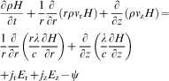
The process using this model is stationary tungsten inert gas (TIG) welding using a tungsten cathode 3·2 mm in diameter with a 60° conical tip. The calculation domain, described in two-dimensional cylindrical coordinates with rotational symmetry around the arc axis, is shown in Fig. 1. The anode is 490 MPa class high tensile strength structural steel, JIS SM490YB. Shielding gas is supplied from outside the cathode on the upper boundary at a certain flowrate. Two-dimensional calculations are conducted. In a two-dimensional axisymmetrical model of stationary TIG welding, the effect of welding speed is virtually considered by converting moving of welding torch into moving of welded plate, and thermal energy stored in anode material is deprived with the increase in moving speed of the welded plate. Thermal energy stored in anode material is deprived with the increase in moving speed of the welding torch. It is based on the fact that when the moving speed of the welded plate becomes higher, the temperature rise in the anode material becomes lower. The governing equations used in the model are as follows.
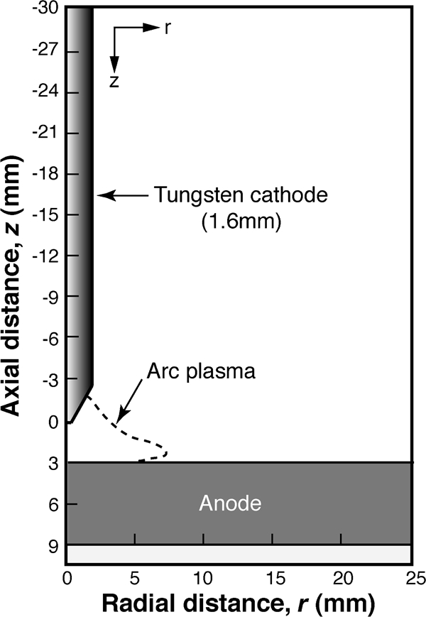
Calculation domain of TIG arc plasma simulation
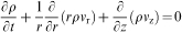
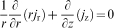
The mass continuity equation is
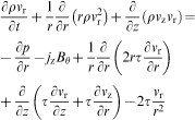
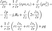

The azimuthal magnetic field Bθ induced by the arc current is evaluated by Maxwell's equation

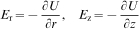
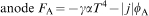
It is necessary to consider the effects of energy transfer at the surfaces of the electrodes. The additional energy fluxes at the cathode and anode are described as follows:

Effect of welding conditions on TIG arc heat source
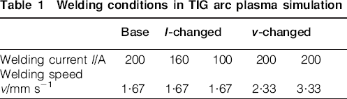
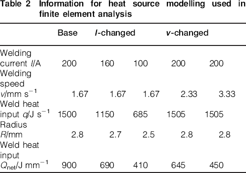
The welding conditions in the numerical simulation of arc plasma process are shown in Table 1. The welding method is TIG welding. The shielding gas is 100%Ar, and the flowrate is 1·67×105 mm3 s−1. To investigate the effect of welding current and welding speed individually, five welding conditions are examined. The base conditions are a 200 A welding current, a welding speed of 1·67 mm s−1 and a 3 mm arc length. Two approaches for the reduction of weld heat input Q ( = IV/v)(J mm−1) are implemented. One is reducing the welding current (I-changed), and the other is increasing the welding speed (v-changed). These welding conditions are applied in both 6 and 12 mm plate thicknesses. As a result, the influence of plate thickness is negligibly small.
Welding conditions in TIG arc plasma simulation
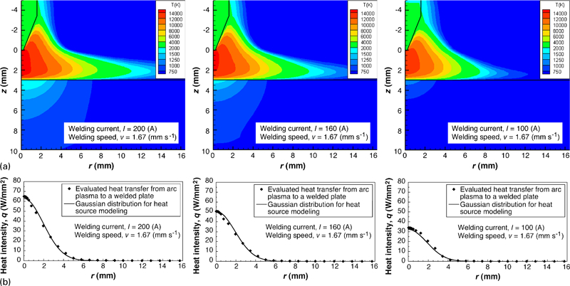
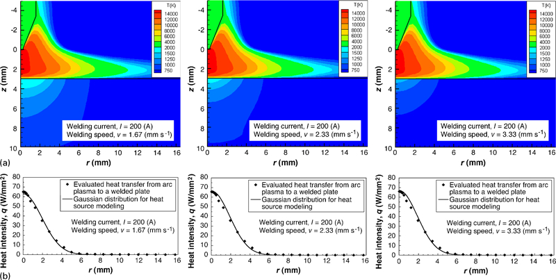
The temperature distributions in TIG arc plasma are shown in Figs. 2a and 3a for each of the three cases of varying welding current and speed for the 6 mm plate thickness. According to these figures, the temperature distribution in TIG arc plasma is significantly affected by the welding current. When the welding current is 100 A, the peak temperature is not more than 14 000 K, and the spread of the area of increased temperature in the radial direction is almost within 12 mm. In contrast, when the welding current is 200 A, the peak temperature is more than 14 000 K, and the spread of the increased temperature area in the radial direction is much greater than 14 mm. The difference in welding speed does not affect either the peak temperature or the spread of the increased temperature area in the radial direction in TIG arc plasma. The heat transfer from arc plasma to a welded plate should be considered based on the differences of temperature distributions in TIG arc plasma due to certain welding conditions. The effects of welding current and speed on the distribution of heat transfer from arc plasma to a welded plate are quantitatively evaluated, as shown in Figs. 2b and 3b. The effects of welding conditions on the heat transfer from arc plasma to a welded plate are summarised as follows: the welding current affects the distribution of heat transfer from arc plasma to a welded plate, and the welding speed does not affect the distribution of heat transfer from arc plasma to a welded plate.
Effect of welding current on characteristics of TIG arc heat source
Effect of welding speed on characteristics of TIG arc heat source
Numerical simulation of weld residual stress and distortion by considering arc plasma process
Simulation model
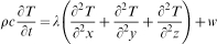
The universal expression of the three-dimensional thermal conduction is as follows
In the elastic–plastic stress analysis, the governing equations are as follows. The equation of the strain–displacement relation is

The constitutive equation is

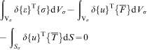
The virtual work principle, shown in the following, can substitute for the equation of equilibrium
 is the tensor of body force per unit volume and
 is the tensor of surface force per unit area. Vσ is the volume of the body and Sσ is the area for which the boundary conditions are given. δ{ } is the amount of virtual change and { }T is the transposed tensor. Equations (13)–(15) are essential in the elastic–plastic stress analysis. Combined work hardening of the material and temperature dependence of the mechanical properties, which include yield stress, Young's modulus and the thermal expansion coefficient, are considered in the mechanical analysis. No restraint is used during the welding process. Details of the mechanical computation have been described in the previous papers.17–
23
is the tensor of surface force per unit area. Vσ is the volume of the body and Sσ is the area for which the boundary conditions are given. δ{ } is the amount of virtual change and { }T is the transposed tensor. Equations (13)–(15) are essential in the elastic–plastic stress analysis. Combined work hardening of the material and temperature dependence of the mechanical properties, which include yield stress, Young's modulus and the thermal expansion coefficient, are considered in the mechanical analysis. No restraint is used during the welding process. Details of the mechanical computation have been described in the previous papers.17–
23
One of the benefits associated with the use of numerical simulation is the diversification possible in generating the heat source model for thermal conduction in welding.24–
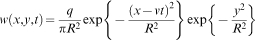
34 At present, to establish the heat source model from the welding conditions, an experiment to obtain information about weld penetration and the temperature profile near the melted zone is imperative. However, a reasonable heat source modelling from the welding conditions should, in nature, be established based on the consideration of weld physical phenomena. In this study, the heat source modelling for welding is established based on heat transfer from arc plasma to a welded plate, which was already calculated by the numerical simulation of TIG arc plasma. The distribution of heat transfer from arc plasma to a welded plate is approximately expressed by the Gaussian distribution
Information for heat source modelling used in finite element analysis
Effect of welding conditions on weld residual stress and distortion
Weld residual stress and distortion are evaluated at the centre of the plate in the welding direction. The relationship between welding conditions and weld residual stress is quantified by the weld heat input Qnet, as shown in Fig. 4. The spread of the area of tensile stress and the local minimum point of compressive stresses are increased with the increase in weld heat input Qnet. The relationship between welding conditions and weld distortion is quantified by the heat input parameter Qnet/h2, where h is the plate thickness, as shown in Fig. 5. The heat input parameter is the influential dominant factor of angular distortion theoretically derived by the similarity rule of the temperature distribution on plate thickness section.35 Weld distortion is not represented by this heat input parameter. Thus, the difference in the effect of welding current and welding speed on weld distortion becomes clear. When the heat input parameter is small, the weld distortion increases with the increase in welding speed. In contrast, when the heat input parameter is large, the weld distortion decreases with the increase in welding speed. This means that the increase in welding speed is equal to the increase in the apparent heat input parameter. The developed numerical simulation using arc physics based heat source modelling thus generates a clearer understanding of the relationship between welding conditions and weld distortion.
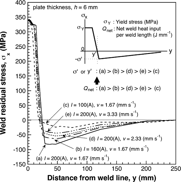
Simulation result on effect of welding conditions on weld residual stress
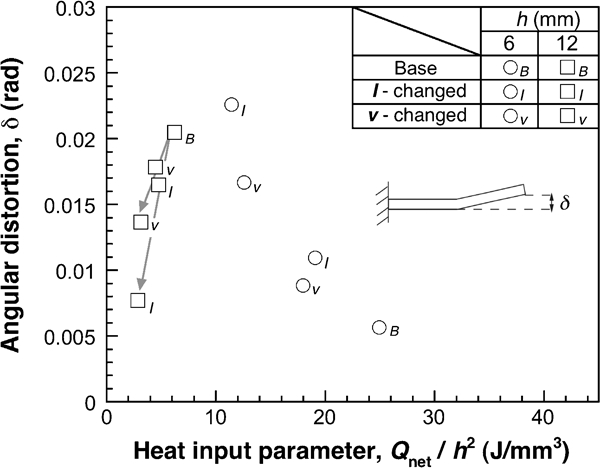
Simulation result on effect of welding conditions on weld distortion
Verification experiment for developed numerical simulation
Experimental procedure
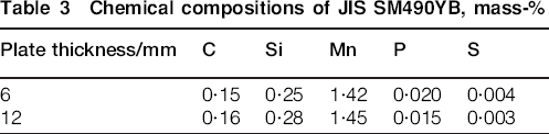
Verification of the developed numerical simulation of weld residual stress and distortion using arc physics based heat source modelling is performed by comparing the experimental result of weld distortion with those in the numerical simulation. This is because weld distortion is more sensitive to temperature distribution than weld residual stress. The steel used in the experiment is a 490 MPa class high tensile strength structural steel, JIS SM490YB. The chemical composition of the steel is shown in Table 3. The configuration of the weld joint used in the experiment is the same as that used in the numerical simulation. The experimental plate is placed on a sill plate because of the heat transfer from the bottom of the welded plate to the air. Weld distortion in the experiment is measured using contact type displacement gauge in ambient temperature. The welding conditions for the verification experiments are the same as those of the numerical simulation, as shown in Table 1.
Chemical compositions of JIS SM490YB, mass-%
Comparison of weld penetration and distortion
The measured weld distortions in all the experimental conditions, including welding current, welding speed and plate thickness, are compared to those simulated, as shown in Fig. 6. In the figure, the configuration of weld penetration is also shown in order to compare the experimental results with the simulation results. The penetration shape generated by numerical simulation does not strictly conform to that of the experiment. This is because convective heat transfer in the weld pool is not considered yet in the present numerical simulation. It is known that the penetration shape in TIG welding is influenced by convective heat transfer in the weld pool.36– 40 The simulation results, however, correspond approximately with the experimental results in both weld distortion and penetration. Especially, the weld distortion simulated conforms very closely to that in the experiment. Thus, evaluating the characteristics of weld heat source highly increases the accuracy of predicting the weld distortion. Furthermore, a more detailed understanding of the effects of the welding conditions on weld distortion is possible. It can be concluded that the combination of arc plasma simulation and mechanical computation is highly effective in the numerical simulation of weld distortion.
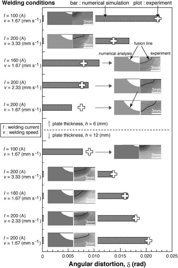
Comparison between simulated and measured weld penetration and distortion
Conclusions
Arc physics based heat source modelling for numerical simulation of weld residual stress and distortion is studied for a more detailed and accurate understanding of the effect of welding conditions on weld residual stress and distortion. The conclusions reached in this study are the following.
For more accurately evaluating the characteristics of heat transfer from arc plasma to a welded plate, numerical simulation of TIG arc plasma is performed. The effects of welding conditions, such as welding current and welding speed, on the distribution of heat input provided to the welded plate are clarified.
An appropriate heat source modelling for the thermal elastic–plastic stress analysis is established. Optional parameters, such as heat input and Gaussian radius, are set based on the result of TIG arc plasma simulation with consideration of the weld physical phenomena. The weld penetration simulated by thermal conduction analysis is almost in good agreement with the experimental configuration measured by macro-observation.
Weld distortion, which is generated by the developed numerical simulation using proper heat source modelling, corresponds with that measured in a welding experiment. The developed numerical simulation leads to a more detailed understanding of the effects of welding conditions on weld distortion.
Footnotes
Acknowledgements
This study was supported by Priority Assistance for the Formation of Worldwide Renowned Centers of Research – The Global COE Program (project, Center of Excellence for Advanced Structural and Functional Materials Design) and also a Grant-in-Aid for Scientific Research (B) (grant no. 20360393), both from the Ministry of Education, Culture, Sports, Science and Technology (MEXT), Japan.