
Abstract
Characterisation of residual stress state was performed in 4 mm low carbon steel plates laser welded in keyhole and conduction mode. Residual stress characterisation was carried out at the ENGIN-X strain scanner at ISIS (Oxford, UK). It was shown that although the maximum magnitude of tensile residual stress is similar in welded specimens manufactured under different welding modes, the distribution profile is quite distinguished. The conduction welding mode resulted in a larger tensile stress domain as compared to the keyhole mode in the longitudinal direction. This also resulted in a different magnitude of balancing compressive residual stress field. Understanding of such different stress profiles is important for application of such advanced welding processes in joining of design efficient structural material.
Introduction
Laser welding has two different operational regimes, conduction and keyhole welding. The key difference between these two modes is the power density applied to the welding area. Conduction mode takes place when the intensity is not sufficient to cause boiling. In keyhole mode, the intensity used is high enough to cause vaporisation and create a keyhole in the melt pool.1, 2 Welding processes generate an integrated structure with a changed microstructure in the fusion and associated heat affected zone along with the creation of a variably distributed residual stress field across the weld. For materials engineers, it is vital to characterise the residual stress state in a welded structure as residual stresses can have a significant effect on the integrity of the structure while in service.3 The other important aspect is the distortion of the welded structure, resulting from the generation of residual stress, which may render the structure unusable or add additional cost to repair before putting it into service.4 In this work, residual stress characterisation has been performed on welds produced by laser welding in keyhole and conduction modes. Residual strain measurement was carried out using a spallation neutron source, and the stress was analysed.
The main cause of residual stress generation is the compressive plastic yielding that occurs ahead of the molten zone as the material heats and expands during welding. The compressive plastic flow is not balanced by tensile plastic flow during cooling, resulting in formation of a tensile residual stress field in and around the weld zone with a balancing compressive stress field further out in the parent material. When the balancing compressive stress field exceeds the critical buckling load, distortion of the welded structure occurs. Therefore, in order to eliminate distortion, it is necessary to reduce the tensile stress field across the weld, which would reduce the compressive stress field generated in order to balance the tensile stress field.5 Currently, there are several techniques that allow the minimisation of the distortions caused by welding.6– 10
The beneficial characteristics of keyhole welding, especially large penetration depth and relatively small heat affected zone, attracted more industrial applications. However, keyhole welding also presents several problems that may lead to high levels of porosities and other weld defects.11– 13 This welding mode, because of its high penetrability, is used for a wide range of applications in different industrial sectors, e.g. pipeline, aluminium alloy welding,14, 15 magnesium alloy welding16, 17 and stainless steel welding.18
Conduction mode is the alternative to keyhole mode of welding. The main advantages of conduction welding are the high flexibility and control over its heat input, which results in high quality welds free of porosity, undercut and humping. Also conduction welding results in spatter free welds as the weld pool is much less turbulent as compared to keyhole mode. This mode operates at a lower power density and does not cause any significant vaporisation.19 At present, the conduction mode of welding is used mostly in the welding of aluminium alloys;20 however, more investigations are now being focused, and new applications for this laser welding mode are being introduced.21 Normally, laser welding is selected over other welding processes because of its characteristics of high power density with low heat input. This results in a reduction in generation of residual stresses and distortion. The application of conduction instead of keyhole mode would increase the heat input and thereby also result in an increase in the residual stresses and the distortion. Therefore, it is necessary to have a comparative quantification and characterisation of the residual stress magnitude and distribution profile for the conduction and keyhole modes of laser welding. This would allow a better understanding on the application based suitability of using these two different welding modes.
Experimental
Preparation of welded samples
An IPGYLR-8000 continuous wave fibre laser with a maximum power of 8000 W and a wavelength of 1070 nm was used in manufacturing the welded specimens. The laser beam is delivered by a fibre of 300 μm diameter. A 125 mm collimating lens and a 500 mm focal length lens were used, which resulted in a beam diameter of 1·2 mm at the focal spot. The focal position, the beam diameter and the beam profile for the lens used were determined using a Primes GmbH Focus monitor system. The welds made with spot diameter larger than 1·2 mm (diameter of the laser spot in the focal position) were obtained by appropriate positioning of the sample in a defocused position of the laser beam to obtain the required beam diameter.
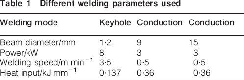
The welding parameters necessary to produce conduction and keyhole mode were determined by conducting several experiments and by observing the macrographs of the weld profiles. The parameters used for manufacturing the specimens using different welding modes are shown in Table 1. All the welds were made in bead on plate configuration.
Different welding parameters used
The material used was a 4 mm thick S355 mild steel. The plates were cleaned using a wire brush and then with acetone in order to avoid contamination of the welds. The chemical composition of the S355 grade is shown in Table 2. For the metallographic preparation, all the samples were mounted, polished and etched using 2% nital etchant.
Chemical composition (wt-%) of S355 mild steel

A schematic view of the specimen and the measurement locations is shown in Fig. 1. The imaginary cross-sectional plane ABCD was near the mid-length of the weld. It can be seen that two different through thickness lines across the weld were measured to understand the variation of stress generation through the thickness.
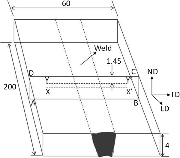
Schematic view of specimen and measurement locations
The welding direction is taken as the longitudinal direction, and other two orthogonal directions across the weld and through the thickness were considered as the transverse and normal directions. Stress analysis was carried out from the measured strain with the reasonable assumption that these are the principal strain directions.
Neutron strain scanning
The neutron diffraction experiment was carried out with an ENGIN-X strain scanner at the spallation neutron source at ISIS, RAL (Oxford, UK). The ENGIN-X strain scanner at ISIS operates on the time of flight (TOF) principle, where the detectors were kept at a fixed position of ±90° to the incident beam. The experimental sample is positioned in a way that two principal strain directions are measured in the two detectors separated by 180°. In ENGIN-X, the experimental specimen is irradiated with pulses of white neutron beam with well defined energy spectrum. The TOF of each neutron in a pulse would depend on the wavelength. Therefore, at a fixed diffraction angle of 90°, neutrons with a specific TOF range would be diffracted by a specific set of crystallographic plane. The details of ENGIN-X could be found elsewhere.22 The most advantageous thing of using a spallation neutron source like ENGIN-X is its ability to simultaneously refine a range of crystallographic planes, thereby minimising the anisotropy that may exist in between different crystallographic directions. In the present experiment, a TOF range of 20–40 ms was used, which resulted in an interplanar spacing of 1·1–2·1 Å. The {110}, {200} and {211} families of crystallographic planes were analysed. An incoming beam dimension of 2×2 mm was used for the longitudinal strain measurement, while 2×10 mm was used for transverse and normal strain directions. A 2 mm collimator was used for all the measurements. The diffraction geometry resulted in a cuboid gauge volume of 2×2×2 mm3 in longitudinal strain direction and 2×10×2 mm3 in transverse and normal strain directions. Refinement of the diffraction spectrum was performed using the General Structure Analysis System programme, which gave an average lattice parameter a of the irradiated volume.23
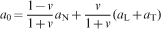
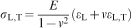
Welding produces a change in composition along the fusion line, which results in a change in the lattice parameter in and around the fusion zone; therefore, for interpretation of strain, it is necessary to measure a stress free reference which would be relieved for any elastic macrostress but would reflect the change in lattice parameter due to compositional variation. However, in the present case, due to the low dimension (∼4 mm) in the through thickness, a direction plane stress condition was assumed, i.e. the normal direction is of insufficient constraint to hold any significant internal stress field. The stress free reference a0 and then the stress were then analysed using the following equations24

Results
Weld macrographs
The cross-sectional macrographs of samples used for characterising the residual stresses are shown in Fig. 2. It is evident that the macrograph shown in Fig. 2a was welded in keyhole mode, whereas Fig. 2b and c was produced in the conduction mode. Residual stresses were analysed in these three welded samples and were compared in this study.
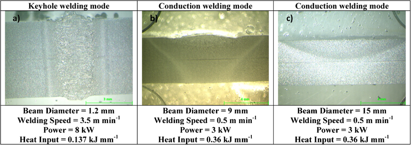
Macrographs of laser welds made in keyhole and conduction welding modes
Residual stress measurements
Figure 3 shows the longitudinal stress variation along the mid-thickness and 1·45 mm from the surface for the specimens welded in conduction mode. It can be seen that there is no through thickness variation of the stress magnitude and distribution across the weld. This is due to the fact that the thermal cycle through the thickness was uniform. Although the actual penetration depth is less than half of the plate thickness, the residual stress magnitude did not show any significant variation as the through thickness dimension is relatively small.
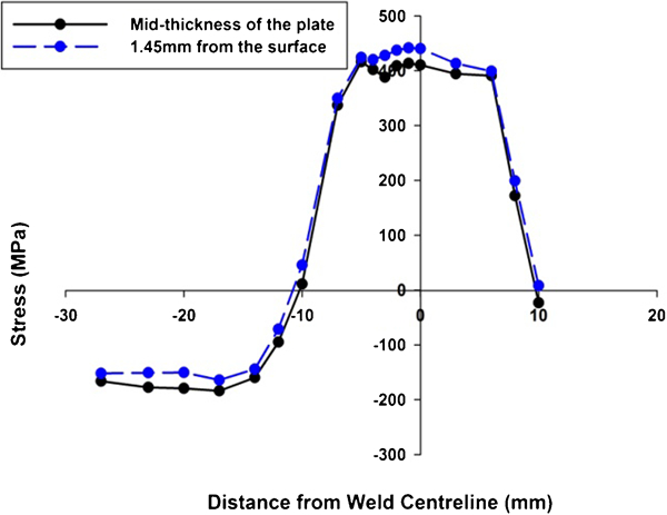
Comparison of longitudinal residual stress at 1·45 mm from surface and at mid-thickness of plate of sample in conduction mode with beam diameter of 9 mm
The mid-thickness of the plate longitudinal stress variation across the weld in the sample produced in keyhole mode and that of the two samples produced in conduction mode are shown in Figs. 4–6. Also shown in these figures is the width of the weld zone on the top surface as measured from the macrographs. It can be seen that the magnitude of the longitudinal residual stress reached up to 400 MPa in all the three specimens.
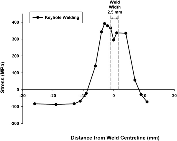
Longitudinal residual stress of keyhole welded sample
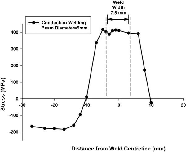
Longitudinal residual stress of conduction mode welded with beam diameter of 9 mm
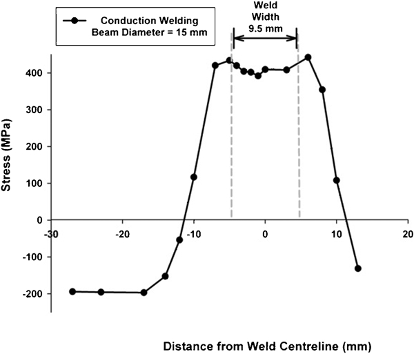
Longitudinal residual stress of conduction mode welded with beam diameter of 15 mm
There is a proportional increase in the width of the peak residual stress plateau across the weld centre with increasing weld width. The weld width is dependent on the laser spot diameter, even if the heat input is identical. However, the dimension of the weld width is not identical to that of the beam diameter. This is because the intensity near the edge of the beam diameter will be less and might not be sufficient to cause melting of the base material. Therefore, the width of the peak tensile stress plateau will depend on both the heat input and the beam diameter.
Figure 7 combines the longitudinal stress variation results presented in Figs. 4–6. The difference in width of the tensile peak for the three welds can be seen. It is also evident that the balancing compressive stress field has also been changed substantially with a much larger value for samples welded under conduction mode. This increased compressive stress field has significant implications in the generation of distortion. Also the stress engineering strategy8, 9, 25, 26 for residual stress mitigation at the time of welding would be different for both welding modes. Keyhole mode is more unstable, which might result in an irregular heat distribution pattern across the weld. The asymmetry of the residual stress distribution profile could be attributed to this. On the other hand, conduction mode is a much more stable process, which means that the heat distribution is more regular and so the residual stress results present a more symmetric profile. Figure 8
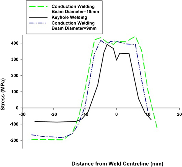
Comparison of longitudinal residual stress of welds obtained in keyhole and conduction modes
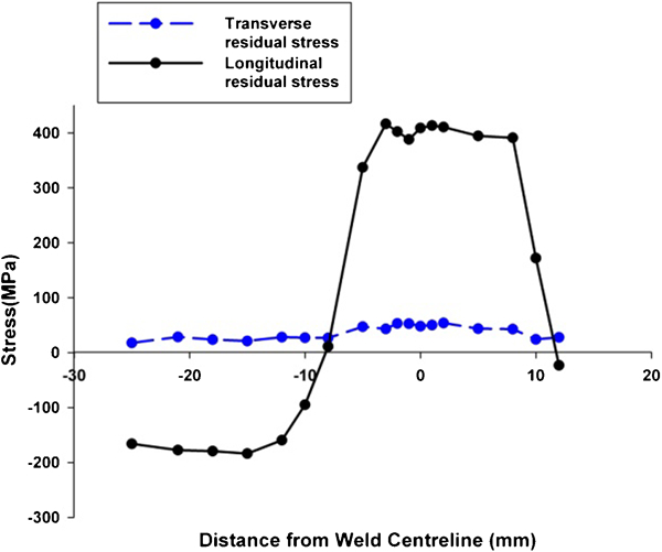
Longitudinal and transverse residual stresses of conduction mode welded with beam diameter of 9 mm
Figure 8 shows the longitudinal and transverse stress distribution profiles for the conduction welded specimen with a beam diameter of 9 mm. It can be clearly seen that the transverse residual stress magnitude is insignificant as compared to the longitudinal stress.
The comparison of the hardness profiles in Fig. 9 shows that the keyhole laser weld has a much higher hardness in the fusion zone compared to the conduction laser weld. This is because the cooling rate in keyhole welding is much faster with a lower heat input as compared to the conduction welding. In keyhole mode, the energy density in the spot is much higher and the heat input is lower as the process can operate faster. Therefore, the cooling rate is much higher in keyhole mode as compared to that in conduction mode. The accelerated cooling rate would result in hard intermediate phase formations, which would influence the hardness profile of the welds. The residual stress generation, on the other hand, remains comparable as both processes are fusion based and cause plastic yielding in front of the weld pool.
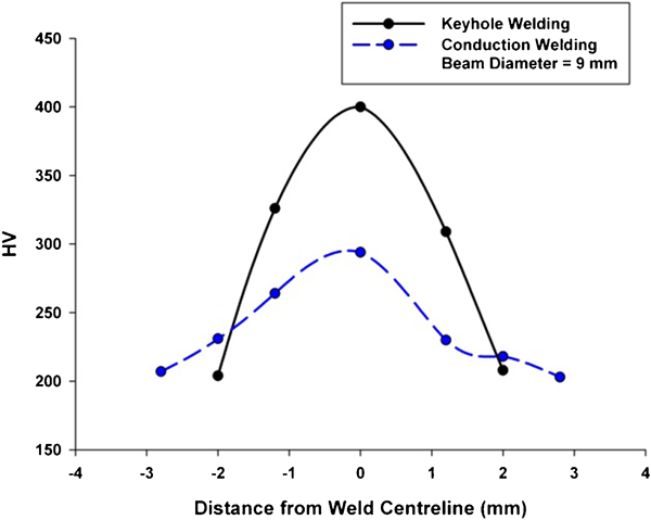
Hardness profiles of keyhole and conduction laser welding
The keyhole and conduction modes of laser welding are unique in their characteristics. The applicability of these two distinctive processes depends on several factors, e.g. productivity requirement, welding set-up tolerance, qualitative requirements and other operative factors. Residual stress characterisation is increasingly becoming important with the introduction of more competitive and design efficient structures. Therefore, characterisation of residual stress profile is important to understand the implication of adopting such processes for safety critical structural welding and fabrications.
Conclusions
The peak magnitude of residual stress has been found to be similar for the keyhole and conduction modes of welding.
There is a significant difference in distribution profile between the two modes of welding.
The area under the tensile domain in the longitudinal direction of the stress is much higher in conduction mode, which means that the balancing compressive stress generated is also much larger. This may have significant implications for structural integrity and distortion of welded components.
The width of peak residual longitudinal tensile stress plateau depends on the heat input and the beam diameter.
In keyhole laser welding, the combination of low heat input with high welding speeds results in a faster cooling rate. This results in a significantly high fusion zone hardness as compared to welds made in conduction mode.