
Abstract
A method is reported with which heat affected zone (HAZ) cracks in a specific region of spot welded joints, made of advanced high strength steels, could be realised. The influence of HAZ cracks on the fatigue behaviour, which is the focus of the contribution, was studied by evaluating the stiffness characteristics as a function of the number of cycles N in comparison with crack-free specimens, i.e. by analysing HAZ and fatigue cracks on the specimen surface and the surface of fatigue fractures containing beach marks. It was found that the fatigue cracks are not initiated at the HAZ cracks. The number of cycles to failure Nf is not significantly reduced for specimens with HAZ cracks. Overall, the examinations did not reveal any influence of HAZ cracks on the fatigue strength of resistance spot welded joints.
Introduction
In recent years, the use of advanced high strength steel (AHSS) in car body shell constructions has steadily increased. Application of AHSS materials for resistance spot welded components helps saving costs and conserving resources due to the higher mechanical strength of AHSS. At the same time, the safety of the passenger cell can possibly be increased.1, 2 The resistance spot weldability of AHSS is well known,3– 5 and the welding parameters can be chosen in a way to obtain welding current ranges for the materials, even with zinc coating,6 which are wide enough to guarantee sufficiently high process reliability. However, the complex microstructure7 and the greater springback behaviour8 of AHSS eventually lead to weld discontinuities,9 whose probable impact on the static strength of joined components has recently been studied.10 The static and dynamic strengths of component-like specimens with weld discontinuities, i.e. cavities in the spot weld, and fatigue cracks were investigated in Ref. 11. Up until now, the influence of weld discontinuities on the fatigue strength has mainly been investigated using specimens with simulated discontinuities, e.g. holes drilled into the spot weld.12 The main reason for such simulation is the high effort necessary to prepare fatigue test specimens containing reproducible discontinuities, especially in the form of cracks. Despite this fact, it is greatly desirable to investigate the fatigue behaviour of spot welded components with spot weld cracks provoked by the welding procedure itself, because the influences of the different types of notches of an artificial discontinuity and of a weld discontinuity can hardly be estimated, which limits the possibilities of investigating the influence of weld discontinuities on the fatigue strength by artificially created discontinuities. Although weld discontinuities might occur sometimes during resistance spot welding of car body shells containing thousands of spot welds each, the process reliability for resistance spot welded AHSS is high, as already mentioned. Therefore, methods have to be established which are able to provoke a reasonable number of cracked spot welds in the laboratory, similar in size and location to the cracks occasionally appearing during production. It is further necessary to ensure a high degree of reproducibility of the discontinuities. Based on production floor experiences, welding parameters and production specific influences suspect to cause cracks in resistance spot welded AHSS are analysed in the first step.
Welding equipment, materials and fatigue test conditions
The spot welded joints were produced using an ac spot welding gun with pneumatic force generation. All fatigue specimens were produced with a spot weld diameter of 6·8 mm (≡5·5t1/2). The dimensions of the specimens were chosen according to the standard13 except the overlap length which is 16 mm.
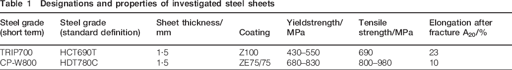
From the hitherto available AHSS, a Transformation Induced Plasticity (TRIP) steel and a complex phase steel with different mechanical strengths were chosen (see Table 1). The sheet thickness of the two base metals was equal, which is advantageous when the fatigue experiments are compared. The TRIP steel was hot dip zinc coated and the complex phase steel was electrolytically galvanised.
Designations and properties of investigated steel sheets
High cycle fatigue tests were performed in a resonance pulsator at a nominal test frequency of 100 Hz. The force controlled tests were performed for one loading condition (R = 0·1, FO = 2·75 kN). In order to be able to compare the behaviour of the different specimens under fatigue loading, the stiffness of the test set-up DS(N) = ΔF/ΔL(N) was measured during the experiment and in situ normalised to its value after N0 = 1000 cycles. The stiffness is used as failure criterion [DS(N)⩽DS(Nf)] to distinguish the number of cycles to failure Nf as described in Refs. 14 and 15. All specimens, crack-free and those containing heat affected zone (HAZ) cracks, were tested until the specimen stiffness has decreased to 70%. Some specimens were prepared with beach marks produced by changing the load ratio to R = 0·7, when the stiffness reached 97·5, 95, 92·5, 90, 85, 80 and 75%. The beach marked specimens where ruptured after the fatigue test in order to analyse the surfaces of the different cracks in the specimen.
Experimental results
Resistance spot welded joints with HAZ cracks
To study the influence of weld discontinuities on the fatigue behaviour, a statistical lot of spot welded specimens must be produced containing those discontinuities in a specific location. To obtain HAZ cracks in specimens, a method was developed with which overlap shear specimens with HAZ cracks oriented towards the fatigue load can be produced in the laboratory. Based on the experience in producing cracks in the electrode indentation area,16 HAZ cracks could be obtained without electrode cooling by combining extremely high welding currents with long welding times and short weld cycles times (Fig. 1). Four spot welded joints were produced within a short time, i.e. in <2 s between finishing each spot welded joint. Because the current shunting increases with each welded joint, the welding current can be chosen beyond the splash limit. It is assumed that the burden of the electrode caps by the provoked splashes, the increased interface temperature between electrode cap and steel sheet due to the lack of electrode cooling and the probable heating of the steel sheet by the preceding spot welds lead to the desired HAZ cracks, which can be obtained with a ratio of 100% in a specific location at the fourth spot welded joint without spilling, as highlighted in Fig. 1. The specific location is an angular location depending on the orientation of the specimen towards the resistance spot welding gun. Therefore, it is possible to choose the orientation of the specimen towards the spot welding gun in a way that the HAZ crack is at the angular position, where the fatigue crack is expected.
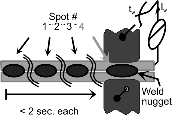
Schematic of weld schedule applied to obtain HAZ cracks in overlap shear specimens
Since the overlap specimens should be produced according to Ref. 13, the geometry of the overlapping part must be fixed before welding the described four spot welded joints. To assure the current shunting effect described above, the spot welded joints must be produced on an electrically connected sheet. These requirements can be fulfilled by the specimen geometry shown in Fig. 2. The fatigue test specimen, located between the two dashed black lines in Fig. 2, is cut out after the welding experiment.
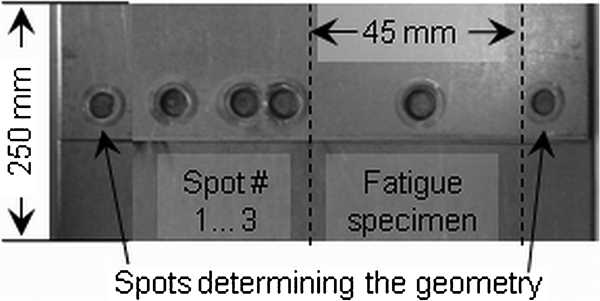
Specimen developed to provoke HAZ cracks (as welded)
The spot welded joints produced with the above described method contain HAZ cracks as depicted in Fig. 3. An experienced operator might find the cracks with an optical microscope (Fig. 3a). In the digital image they are hard to distinguish. A sure method for detecting the HAZ cracks is the dye penetrant test, which clearly shows the existence of the crack (Fig. 3b). Cracks like these are not detectable in two-dimensional X-ray images (Fig. 3c), when the X-rays, as it is usual for random car body part inspections, are simply applied perpendicular to the sheet surface and the image is not magnified. They might be detectable, when the correct angle for the radiography is chosen, or a computer tomography is made. Clearly distinguishable in size and location is the crack after removing the zinc coating (Fig. 3d). The zinc coating was therefore removed at all specimens investigated in this work. The cross-sectional image in Fig. 3e) shows that the crack is located in the HAZ of the spot welded joint and has approximately a depth of one-third of the sheet thickness. For the specimens made of HCT690T, crack indentation depths of 0·5–0·9 mm (from 1/3 to 2/3 of the sheet thickness) were obtained. For specimens made of HDT780C, the HAZ crack depth of the beach mark specimen was 0·4 mm. The HAZ cracks obtained in the specimens made of HDT780C were in total smaller than those obtained in specimens made of HCT690T. The size of the cracks is similar to those occasionally obtained in the highly automated car body mass production in components made of AHSS. The obtained HAZ cracks, produced very close to typical production conditions, are therefore highly suitable for fatigue tests. In order to reduce the costs for the fatigue tests, the HAZ cracks should also be located at the worst position. Typically, the fatigue cracks propagate through the sheet in the HAZ, as pointed out in Fig. 3e by black arrows. As an additional benefit of this method, HAZ cracks can be produced located where the assumed fatigue crack path is expected (see Fig. 3d and e), because the HAZ cracks appear at a specific angular location depending on the orientation of the specimen towards the welding equipment.
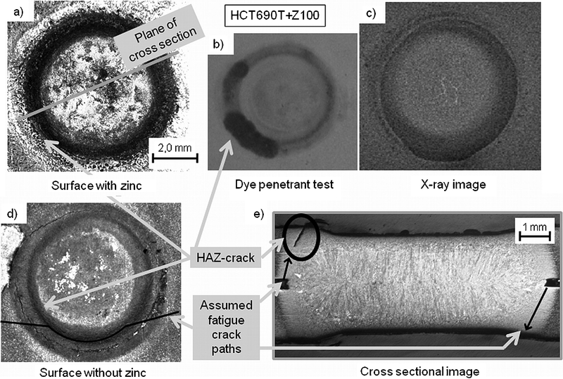
Example of HAZ cracks obtained in HCT690T using weld schedule shown in Fig. 1
Fatigue experiments by loading until total fracture
In order to evaluate the influence of HAZ cracks on the fatigue behaviour of the spot welded joints, fatigue experiments were realised with crack-free specimens and specimens containing weld discontinuities. The fatigue behaviour of the spot welded joints is compared by means of the normalised stiffness. The crack-free specimens reached, when the failure criterion of 70% stiffness reached Nf's from approximately 150 000 to 300 000 cycles (Figs. 4 and 5). The specimens made of HDT780C in Fig. 5 show less scatter than those made of HCT690T shown in Fig. 4.
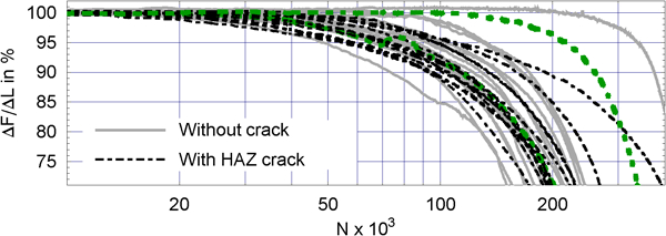
Stiffness characteristics of crack-free (grey, solid lines) and HAZ cracked (black, dashed lines) specimens, base metal: HCT690T
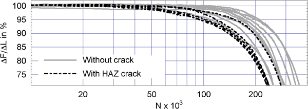
Stiffness characteristics of crack-free (grey, solid lines) and HAZ cracked (black, dashed lines) specimens, base metal: HDT780C
In this figure, the stiffnesses of cracked and crack-free specimens are compared. In total, 15 specimens with HAZ cracks were tested. They do not show any influence on the stiffness characteristics (black, dashed lines) in comparison with the crack-free specimens (grey, solid lines). The results obtained for the hot rolled HDT780C are similar, as shown in Fig. 5. Five specimens were tested. All stiffness characteristics are in the range of the crack-free samples, no significant reduction of the Nf's was found. Even though the mean value of Nf is 366 000 and 250 000 for the crack-free and HAZ cracked specimens respectively, the high standard deviation of the crack-free specimens of 83 000 cycles, which show the usual scatter of a fatigue experiment, and the lower number of specimens investigated for the hot rolled steel make the reduction of Nf not significant. The following analysis of the fatigue crack initiation and propagation in those specimens indicates that the reduction of Nf measured for the HAZ cracked specimen maybe result from other influences, e.g. the different production procedures of the crack-free and HAZ cracked specimens.
Furthermore, the stiffness characteristics presented in these diagrams show that the crack initiation phase during the fatigue tests was not influenced. The period of constant stiffness of 100% lasts for both, crack-free and HAZ cracked specimens, ∼20 000 cycles for HCT690T and a little more, ∼50 000 cycles for HDT780C.
The crack propagation phase will be discussed with the focus on the HAZ cracks in the following. The fatigue loading leads to three constellations of fatigue and HAZ cracks:
no fatigue cracks at all in the vicinity of the HAZ crack
during its evolution, the fatigue crack propagates into the HAZ crack and combines (Fig. 6a)
the fatigue crack propagates parallel to the HAZ crack, i.e. crosses it (Fig. 6b).
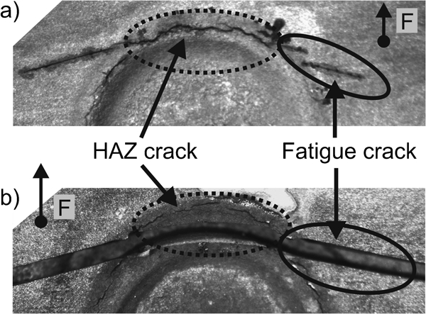
Surface of spot welded joints after fatigue test
All three constellations were observed randomly during the experiment. Figure 6 shows the two latter possibilities, which are of interest in this context. Whose constellation of fatigue crack occurs has no influence on Nf. For example, the specimen with the crack combination shown in Fig. 6a attained high Nf's, as highlighted in Fig. 4 in dark green. Also highlighted in dark green is the specimen of Fig. 6b, which shows medium Nf's. However, in this specimen, the fatigue crack propagates completely parallel to the HAZ crack and met it only in the region where the fatigue crack propagates into the base metal. These examples show that the fatigue crack is not influenced by the HAZ crack. Especially, it appears that the HAZ cracks are not the initial cracks for the fatigue failure. This finding approves the experimental results of the stiffness characteristics, where a similar crack initiation phase of the HAZ cracked specimens was found. Furthermore, even if the fatigue crack combines with a HAZ crack at ∼95% stiffness, an influence on the characteristics (e.g. a sudden drop of the stiffness), and therefore of the attained Nf's was not observed. This will be discussed further in the next section.
A cross-section of a specimen with a fatigue crack propagating parallel to the HAZ crack (as depicted in Fig. 6b) is shown in Fig. 7. In Fig. 6a, the plane of the cross-section is indicated. It includes three branches of fatigue cracks as well as the crossing of the fatigue crack and the HAZ crack. The most left fatigue crack branch initiated at the faying interface, as is usual for spot welded joints. The HAZ crack therefore is not suspect to act as an initial crack. A branch of the fatigue crack crossed the HAZ crack while propagating into the base metal. The surface image (Fig. 7b) shows that the crack path is not influenced by the HAZ crack. Further investigations to confirm these findings are based on beach mark specimens discussed in the next section.
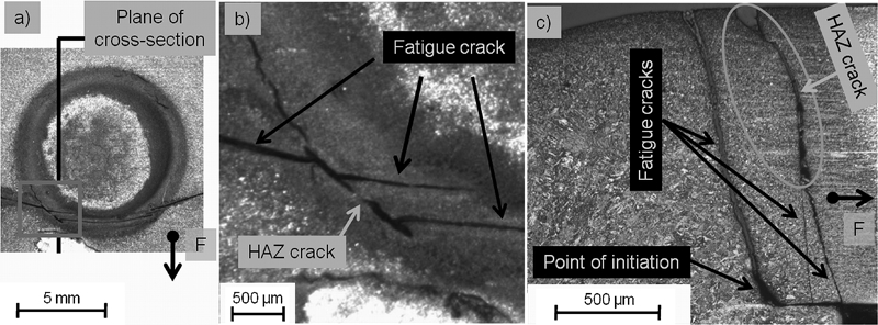
HCT690T specimen with HAZ crack after fatigue test
Development of fatigue crack during cyclic loading
Because the stiffness is in situ normalised and measured during cyclic loading, the load ratio can be changed automatically at user specified values of the stiffness. In comparison to the initially applied R value of 0·1, for a higher load ratio (R = 0·7) the fatigue crack surface becomes more dark. The beach marks were produced using a constant maximum force for both R values. It is thus possible to distinguish the propagation direction and the size of the fatigue crack at specific stages of the test. A scanning electron micrograph of a HCT690T specimen with beach marks is shown in Fig. 8. On the top of the image on the left hand side, the area of forced fracture, caused by the quasi-static rupturing of the specimen after the fatigue test, can be clearly distinguished from the area of the fatigue crack and the HAZ crack surface (lower left and right part respectively). Half elliptic, darker beach marks can be seen as well. As simulated earlier,17 the fatigue crack propagates elliptically through the sheet, and the initiation point, as assumed in the section before, is confirmed to be located in the faying interface. The centre point of the ellipses, located in the lower left corner of the image, clearly indicates the initiation point. In the shown case, the fatigue crack did not even combine with the HAZ crack. The detail on the right hand side shows a small area with the typical structure of a forced fracture between the fatigue crack and the HAZ crack.
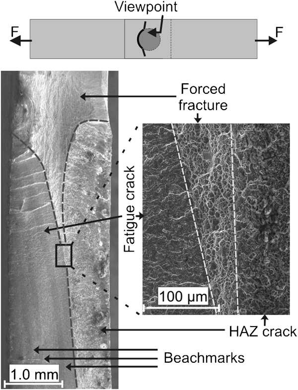
Specimen with beach marks and HAZ crack (HCT690T)
Figure 9 shows fatigue crack surfaces with beach marks, upper (Fig. 9a) and lower (Fig. 9b) sheet, of spot welded joints made of HDT780C. Again, the beach marks reveal an elliptical propagation of the fatigue crack. Heat affected zone cracks on both sides of the spot welded joint were met by the fatigue crack during its propagation and combined with the HAZ crack in the lower sheet (case 2), but crossed it in the upper sheet (case 3). It can be clearly seen that the fatigue crack propagated around the HAZ crack. The area of the HAZ crack, which is small in comparison to the area of the fatigue crack obtained at the end of the fatigue test, when Nf is measured, might explain why the Nf's are not significantly reduced by the HAZ cracks.
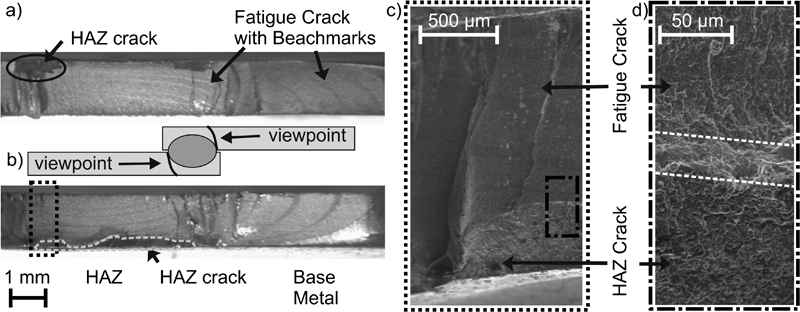
Specimen with beach marks and HAZ crack (HDT780C)
Figure 9c and d shows a scanning electron micrograph of the fatigue crack surface and of the HAZ crack surface. Again, between the two crack surfaces a small region with a different morphology is observed. The different morphology indicates a fracture mode in that area which is different from the mode causing the fatigue crack and the mode causing the HAZ crack. Most probably, the region is ruptured by a forced fracture.
Conclusions
Heat affected zone cracks with typical sizes, as they occasionally might occur in resistance spot welded joints made of AHSS, could be provoked in order to investigate the influence of this special type of weld discontinuities on the fatigue behaviour of the spot welded joints. The HAZ cracks could be produced by welding of four successive spot welded joints on one sheet. The technique for bringing in HAZ cracks applies, due to current shunting, very high welding currents, which might be the reason for the high rate of HAZ cracked specimens obtained by this method. The HAZ cracks could be produced in the worst location concerning the fatigue load in order to reduce the effort for the fatigue tests.
It was found that the numbers of cycles to failure were not significantly reduced by HAZ cracks in spot welded joints made of cold rolled (HCT690T) and hot rolled (HDT780C) AHSS base metals. Also, the fatigue crack path is not influenced by the HAZ cracks. Furthermore, the HAZ crack area enclosed by the fatigue crack, i.e. the reduction of the load bearing cross-section, is small in comparison to the entire fatigue crack area. The stiffness characteristics, the cross-sectional image and the beach mark specimens prove that HAZ cracks of the investigated size and orientation do not initiate the fatigue crack.
Footnotes
Acknowledgements
This study was funded by the Forschungsvereinigung Stahlanwendung (FOSTA) within the Project P802. The authors want to express their appreciation for the fruitful discussions concerning weld discontinuities to the members of the expert committee.