
Abstract
This paper investigates a trailing heat sink, which was designed and applied to friction stir welding (FSW) in order to control the residual stresses and welding distortion. Residual stresses, residual plastic strains and welding distortion of 2024-T3 and 5083-H321 Al sheets welded by FSW with and without the trailing heat sink were compared. The optimal placement of the heat sink was discussed. The results revealed that the reductions in peak tensile stresses were 66% for 2024-T3 and 58% for 5083-H321 by application of the trailing heat sink in FSW. In addition, the welding distortion could be reduced drastically by this method. The 5083-H321 sheet with a size of 1000×100×3·5 mm welded by this method was very flat and had almost no distortion. This method achieved in-process control of stresses and welding distortion, without additional complicated work before or after welding operation.
Introduction
Friction stir welding (FSW) was introduced for the first time in 1991 by The Welding Institute. The process is used increasingly in a wide range of applications and plays an irreplaceable role in welding aluminium alloy.1– 3 Although FSW produces welds of excellent mechanical properties, recent works have substantially showed that there are significant levels and complex distributions of the longitudinal residual stresses (LRSs) in the welded structure of aluminium alloy.4– 6 The residual stress can influence the service performance of the friction stir welded components with respect to fatigue and corrosion properties.7, 8 As aluminium alloys have high thermal conductivity (triple that of steel), besides high levels of residual stresses, the localised heating and the non-uniform cooling during welding can easily result in undesirable deformation or distortion of the welded structure. In the aerospace industry, the welding distortion always causes tremendous fit-up problems in assembling and affects the performance of the welded structure in service. It is essential to find good methods to control the residual stress and the welding distortion.
Recently, a number of studies have focused on controlling the residual stress of the friction stir welded structure. Lombard et al. investigated the effect of varying welding parameters on the residual stress in friction stir welds of aluminium alloy AA 5083-H321 and found that there was a good correlation between the maximum LRS and the feedrate.9 Ali et al. used shot peening to reduce the tensile LRS (TLRS) and presented that the TLRS introduced in the thermomechanically affected zone during welding became compressive after peening.7 Altenkirch et al. used the roller tensioning technique to control the residual stress in thin butt FSW welds. Significant reductions in TLRS were observed with proper loading.6 In particular, Richards et al. investigated the potential of global mechanical tensioning for controlling the residual stress in FS welds and found that this technique, with sufficient applied force, could even be used to generate compressive residual stresses along the weld line.10, 11 Richards et al. have also pointed out that this technique suffered from some important practical limitations. Because this technique requires very large loads, this technique could only be applied to linear welds.12 Although some of these mechanical methods can control the residual stresses of FSW welds effectively, these methods need additional complicated work before or after welding operation.
Besides the abovementioned mechanical methods, local thermal tensioning methods have also been developed to control welding residual stresses. In the field of arc welding, the local thermal tensioning technique has previously been developed by Guan et al. and referred to as dynamically controlled low stress no distortion welding (DC-LSND). In this method, a trailing heat sink was used to generate active cooling and thermal tensioning on the hot metal between the heat sink and the heat source. Owing to the thermal tensioning, the incompatible compressive plastic strains (ICPSs; misfit strains) could be relaxed. Therefore, residual stresses and welding distortion could be minimised effectively.12 Gabzdyl et al. used the DC-LSND technique in laser welding and FSW and found that distortion of 1·6 mm 304L sheets amounting to 20 mm from flat could be completely eliminated. In their DC-LSND process, the thermal tensioning was achieved by spraying a cryogenic liquid, delivered from a nozzle which moved along with the heat source, to the solidifying weld metal at the rear of the laser spot.13, 14 Soul et al. and Li et al. applied the DC-LSND technique in arc welding titanium alloy sheets and studied the welding temperature field. Their results showed that the high temperature region was limited, and the maximum temperature of the sample was much lower than that of conventional arc process.15, 16
Since there are no arc or plasma gasses involved in the FSW process, DC-LSND methods are better suited to FSW than fusion welding. However, to date, very few studies have focused on using the DC-LSND technique to control welding distortion and residual stresses in the FSW process. The current authors have designed a water spray array jet heat sink and applied it to the FSW process. Compared with conventional FSW joints, this work showed significant reductions in peak residual stresses and narrower distribution of tensile stresses.17 Richards et al. recently demonstrated that with appropriate cooling strategies, using liquid CO2 cooling systems could reduce residual stresses significantly. The controlling effect depended on the size, power and positioning of the cooling sinks. A heat sink placed as close as possible behind the heat source had the greatest effect on reducing the build-up of tensile stresses.12
The aims of this paper are twofold. First, the trailing heat sink applied to the FSW process was designed. Afterwards, the active cooling system was established, which could provide an in-process control of the welding stress and distortion in FSW Al sheets. Second, the effects of the trailing heat sink were evaluated. For this purpose, the residual plastic strain, the residual stress and the welding distortion were compared between sheets welded with and without heat sink.
Experimental
Material and welding conditions
Two different aluminium alloys were investigated in the present study. The first alloy was 2024-T3 with a sheet size of 400×120×1·6 mm. The second alloy was 5083-H321 with a sheet size of 1000×100×3·5 mm. The yield stresses σ0·2 of these metals were given as 335 MPa for 2024-T3 and 228 MPa for 5083-H321. The FSW experiments were performed at the Chinese FSW Center of the Beijing Aeronautical Manufacturing Technology Research Institute. The stir tool was tilted 2° from the vertical direction during the welding process. The shoulder diameter of stir tools was 10 mm. The welding tool pins had tapered cylindrical shapes with threaded profiles and pins with sizes of 1·43 mm (1·6 mm thick 2024 sheets) and 3·3 mm (3·5 mm 5083 sheets). The tool traverse and rotation speeds used were 100 mm min−-1 and 1500 rev min−1 for 2024 sheets and 160 mm min−1 and 600 rev min−1 for 5083 sheets respectively. All the welds for the experiments had no defects that were detected by X-ray non-destructive examinations.
Measurements of residual stresses and residual plastic strains
Residual stresses and residual plastic strains were investigated by a destructive method called ‘slot sectioning stress relaxation method’. Sections were cut through the specimen according to the testing points. Plastic strains and residual stresses in the longitudinal direction were measured by a strain gauge. Pairs of small holes in each section were drilled completely through the thickness of the plate before welding. For each pair of holes, the centre to centre distance L0 was measured by the mechanical strain gauge. After welding, the distance of each pair of holes L1 was measured again. Then, each lath including a pair of holes was cut through the sheet, and the distance of holes L2 was measured for the third time. 18 18,19
The released strain ϵe can be computed by

The residual plastic strain ϵp in the longitudinal direction can be computed by

The residual stress and the residual plastic strain of each testing position were repeatedly measured five times. In order to show the sensitivity and repeatability of this testing method, plots of stresses and strains were shown in the experimental results with the mean values, the maxima and the minima. As the test holes in the range of welding pass were destroyed by the stir tool, the residual plastic strain cannot be measured in the welding pass.
Welding distortion measurement
The welding distortion in a thin sheet structure has many shapes, such as longitudinal shrinkage, transverse shrinkage, angular distortion and longitudinal bending.20–
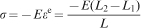
23 In friction stir weld sheets, the distortion outcomes are dominated typically by bending and buckling caused by intricate longitudinal stresses. Distortion of Al sheets welded by FSW was measured by average bending distortion H and average longitudinal flexibility f. The average bending distortion H can be computed by

Measurement of welding distortion a bending distortion b longitudinal flexibility
Establishment of active cooling system
In welding, the heating and cooling cycles are not uniform. It leads to unmatched expansion and contraction forces. As a result, the ICPSs are generated in the welds. As the welded area becomes colder and has more deformation resistance, ICPS cannot be recovered in the welding process. After welding, the welded sheet with significant ICPS always presents undesirable distortion and complex residual stress. Using a heat sink could control the ICPS very well, as this method could modify the thermal field effectively.16– 19 Richards et al. proved that placing a heat sink ahead of the tool was relatively ineffective in modifying the thermal field, even with the maximum cooling intensity. However, a heat sink placed as close as possible behind the tool could drastically modify the local thermal field;12 therefore, in this study, the heat sink is set behind the tool as a trailing heat sink.
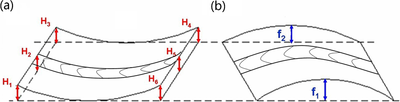
As the temperature field of the FSW had an elliptical distribution near the stir tool,24, 25 the trailing heat sink is designed as a U shaped structure (Fig. 2a). The impinging holes, which jet coolant to the weld surface during the welding process, are arranged in an arc and fed at the same rate. The distance between a single impinging hole and the stir tool in the welding direction is bigger than in the transverse direction, in accordance with the temperature field distribution of FSW. This spread pattern of impinging holes, not only can give an effective cooling but also can prevent the coolant from running into the welding line. In the active cooling system (Fig. 2b), the coolant is a mixture of cooling water and compress air, which is mixed by an atomiser. With high pressure, the compressed air provides the coolant with energy and high jet impinging speed. Based on the microjet impingement cooling theory, when the coolant interacts with the welded area, a thin shear layer, which has precise active area and high convective heat transfer coefficient, can be generated.26– 28 The shear layer, which is very thin in thickness and resembles a bell jar in shape,27– 32 could work precisely and avoid interacting with the stir tool. Therefore, the coolant could cool the welded area effectively and give little effect on the heat input in welding.31, 32 An air nozzle is set in front of the stir tool, with the view of keeping the coolant from running into the welding line and interacting with the stir tool.
Schematic diagrams showing a trailing heat sink and b active cooling system
Results
Effect of trailing heat sink on residual stresses
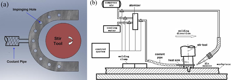
The LRS measurements of 2024-T3 and 5083-H321 are shown in Fig. 3. In friction stir welded sheets without heat sink (conventional FSW), TLRS presents typical M shaped profiles. It can also be found that the TLRS has an asymmetric distribution along the welding centreline, which resulted from the differences in friction forces between the advancing and retreating sides. In terms of the maxima and the location of the tensile region, the stress profiles are generally in good agreement with those in reported literatures. 5 5,9 Significant levels of TLRS occur within and near the active zone of the tool shoulder. The maximum TLRS values are 140 MPa for 2024-T3 and 155 MPa for 5083-H321. The position of the peak tensile value occurs close to the advancing side of the tool shoulder periphery. It is related to the high temperature at the shoulder periphery. Compared with the maximum TLRS values, values decline slightly at the weld centreline where the TLRSs are 95 MPa for 2024-T3 and 123 MPa for 5083-H321. The relaxation of residual stress is mainly due to the plastic deformation, which occurs in a wide region under the footprint, as Richards et al. explained.10, 11 Beyond the active zone of the tool shoulder, the residual stress curves drop sharply and rapidly change to compressive stresses in order to keep the stresses balanced in the whole sheet.
Longitudinal residual stresses of sheets welded by FSW with and without heat sink
The sheets welded by FSW with trailing heat sink have similar shapes in residual stress curves. However, the peak TLRS, as well as the width of the tensile regions, reduces drastically (Fig. 3). The maximum tensile values of 2024-T3 and 5083-H321 drop to 48 and 65 MPa respectively. Compared with conventional FS welds in peak TLRS, the reductions are 66% for 2024-T3 and 58% for 5083-H321 respectively. Although the trailing heat sink only works within and near the tool shoulder, stresses are adjusted simultaneously beyond the active region, as shown in Fig. 3. It is the reaction of stresses in the material surrounding the weld to balance the reduction in TLRS in the weld region. Compressive stress magnitudes also change obviously, when the trailing heat sink is applied. The maximum compressive values of 2024-T3 and 5083-H321 drop to −27 and −19 MPa respectively. Compared with the peak compressive stresses seen in conventional FS welds, the reductions are 39% for 2024-T3 and 50% for 5083-H321. Furthermore, for the 2024-T3 sheet, towards the plate edges, the compressive stresses can be virtually eliminated. The reduction in the compressive stress level towards the plate edges is good for controlling the welding distortion, particularly for decreasing or even eliminating the buckling deformation of welded thin plate structures.
Effect of trailing heat sink on residual plastic strains
As distortion and residual stress both arise from the mismatch of thermal strains during the welding process, the investigation of strains is very important. The longitudinal residual plastic strain (LRPS) curves are shown in Fig. 4, with the test positions as the abscissa and the LRPS as the ordinate. Figure 4 shows the positive coordinate of the ordinate as the tensile LRPS and the negative coordinate as the compressive LRPS. Compared with the conventional FSW, using the heat sink can effectively narrow the distribution of compressive LRPS and reduce the strain values. The peak values of compressive LRPS exist near the stir tool shoulder. Accordingly, tensile residual stresses (as shown in Fig. 3) attain the maxima in the same positions. When the trailing heat sink is applied to the welding process, both compressive LRPS (Fig. 4) and tensile residual stresses (Fig. 3) could reduce consistently.
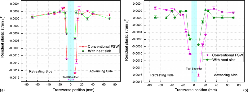
Longitudinal residual strains of sheets welded by FSW with and without heat sink
The reduction in the compressive LRPS results from the active cooling of the trailing heat sink. In the FSW process, the trailing heat sink cools the weld region and generates thermal tensioning on the high temperature metal between the heat sink and the stir tool. As the thermal tensioning counteracts with the ICPS, which has been generated by unmatched expansion and contraction forces in the welding process, the ICPS can be recovered. As a result, the compressive LRPS in the join becomes lower. Accordingly, the tensile residual stress and the welding induced distortion can also be controlled.
Effect of trailing heat sink on welding distortion
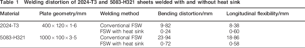
The welding distortions of 2024-T3 and 5083-H321 sheets are shown in Table 1. In conventional friction stir welded 2024-T3 sheets, there are significant distortions, with values of 9·82 mm in bending distortion and 8·38 mm in longitudinal flexibility. However, when the trailing heat sink is applied to the FSW process, the welding distortion reduces drastically, with values of 0·24 mm in bending distortion and 0·60 mm in longitudinal flexibility. In particular, in big size sheets welded with the trailing heat sink, the effect of distortion controlling is obvious. Figure 5 shows the distortion of 1000×100×3·5 mm 5083-H321 sheets welded by FSW with and without the trailing heat sink. The 5083-H321 sheets welded by FSW with the trailing heat sink are very flat and have almost no distortion. Since using the trailing heat sink can effectively control the value and the distribution of the residual stress and the ICPS, the welding distortion can be reduced effectively. Owing to the active and in-process way of controlling, the distortion can be reduced in the welding process without additional complicated work before or after the welding operation.
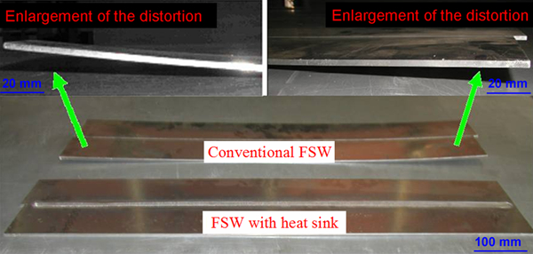
Distortion of 1000×100×3·5 mm 5083-H321 sheets welded by FSW with and without heat sink
Welding distortion of 2024-T3 and 5083-H321 sheets welded with and without heat sink
Discussion
The efficacies of active cooling for welding distortion and residual stresses in friction stir welds are influenced by several factors, including weld temperature, ambient temperature, traverse speed and heat sink positioning.12, 13 Li et al. and van der Aa et al. have looked into the positioning of heat sinks in DC-LSND and found it to be the most important factors for maximising the relief of residual welding stresses.18, 33 Richards et al. found that a leading heat sink was much less effective in modifying the thermal field and reducing the residual stresses. In order to enhance the controlling efficacy, the heat sink should be placed behind the stir tool as a trailing heat sink.12 Li et al. and van der Aa et al. found that the effective active region of a trailing heat sink was limited. If the heat sink was placed too far behind the heat source, then the controlling effect could be reduced.18, 33
The time when the material is hot enough for the cold sink to affect it depends on the material's flow stress with temperature. The flow stress needs to be very low for tensioning to work. As aluminium alloys have good plasticity and low flow stress near 400°C,34 thermal tensioning should be operated on the welds at this temperature. The thermocouple positioned at 6 mm distance from the weld centreline shows the thermal curve of 2024 sheets (1·6 mm thick) welded by conventional FSW (Fig. 6). A cutoff of 400°C is presented in Fig. 6. As the time duration of the temperature curve in the red shadow area (above 400°C) is te, the heat sink should work in this period. With the tool traverse speed V, the optimal distance S between a trailing heat sink and the stir tool can be computed by

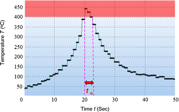
Thermal curve of friction stir welding 2024-T3
In this study, the tool traverse speed V is 100 mm min−1, and the effective acting time of the heat sink te is 2·96 s. The optimal distance S computed by the above formula is ∼4·93 mm. The optimal distance could vary with different welding parameters. For example, if FSW performs at lower traverse speeds, then it enhances the welding heat input and increases the time per unit area for heat extraction between the welds and the heat sink; therefore, the optimal distance would vary. However, in FSW Al sheet, since there is no melting in the process, the welding peak temperature is not high either, and the temperature reduction is sharp. Therefore, the effective acting time of the heat sink is very short in fact. As a result, the optimal distance between a trailing heat sink and the stir tool is limited. This computed optimal distance (4·93 mm) is short to place the heat sink, as the heat sink and the stir tool have their own shape sizes. Therefore, the heat sink should be placed as close as possible to the edge of the stir tool in FSW Al sheets, as Richards et al. and van der Aa et al. observed.
Conclusions
A trailing heat sink was designed and applied to the FSW process. The efficacy of the heat sink for controlling residual stresses and welding distortion was investigated. The work supports following conclusions:
Compared with conventional FS welds, the reductions in peak tensile residual stresses are 66% for 2024-T3 and 58% for 5083-H321 by application of the heat sink in the FSW process.
The welding distortion of both 2024-T3 and 5083-H321 sheets can be reduced drastically using the trailing heat sink. The 5083-H321 sheet with a size of 1000×100×3·5 mm welded by this method is very flat and has almost no distortion.
Using the trailing heat sink can effectively control the distribution of the compressive residual plastic strains and reduce the strain values.
The effective active region of a trailing heat sink is limited. In order to obtain the greatest controlling effect, the heat sink should be placed behind the stir tool as close as possible in FSW Al sheets.
Using the trailing heat sink in the FSW process can achieve in-process control of stresses and welding distortion, without additional complicated work before or after the welding operation. This method is practical and easily operated.
Footnotes
Acknowledgements
The authors would like to thank the staff of the Chinese FSW Center for their support during the experiment. W. T. Han would like to thank his friend R. Cunningham and Y. Li for literal proofreading before submission.