
Abstract
Aluminium and copper plates with 3 mm thickness were successfully friction stir lap welded at a lower rotation rate of 600 rev min−1 using a larger pin 8 mm in diameter. Good metallurgical bonding on the Al/Cuinterface was achieved due to the formation of a thin, continuous and uniform Al–Cu intermetallic compound layer. Furthermore, many Cu particles consisting of pure Cu and intermetallic compound layers were generated at the lower part of the nugget zone, forming a composite structure with increased hardness. A lower rotation rate resulted in a decrease in annealing softening in the heat affected zone (HAZ), and a larger diameter pin increased the Al–Cu bonding area. These factors resulted in that the friction stir welded lap joint exhibited a high failure load of 2680 N with failure in the HAZ on the aluminium side.
Introduction
In recent years, bimetallic joints, particularly aluminium to copper, are increasingly being used in a variety of electrical applications. To meet the requirements from the electric power industry, the bolted Al–Cu joints have been replaced by welds.1 However, the welding of aluminium to copper by fusion welding is generally difficult because of the wide difference in their physical, chemical and mechanical properties and the tendency to form brittle intermetallic compounds (IMCs). Therefore, solid state joining methods such as friction welding, roll welding and explosive welding have received much attention.1– 6 These methods, however, have a few drawbacks. For example, friction welding and roll welding lack versatility, and explosive welding is involved in safety problems.
After two decades of development, friction stir welding (FSW) has become a viable and important welding and manufacturing technology, especially in aerospace and automotive applications involving aluminium alloys.7 Recently, interests have increased for FSW of dissimilar metals and alloys, particularly systems that are difficult or impossible to weld by conventional fusion welding. 8 8,9 Furthermore, a few preliminary studies have reported on FSW dissimilar lap joining.10– 15 However, most previous studies performed FSW lap joining of dissimilar materials at higher rotation rates. For example, Chen and Nakata 14 14,15 chose a high rotation rate of 1500 rev min−1 in the FSW lap joining of Mg alloy to Al alloy and Mg alloy to steel. For Al–Cu lap joints, Abdollah-Zadeh et al. 10 performed FSW investigations at a wide rotation rate range of 750–1500 rev min−1. It was found that the sound joints with high mechanical properties could be obtained only at higher rotation rates.
It is well documented that the IMCs formed easily at high temperature,15– 17 and the maximum temperature was determined mainly by the rotation rates. 18 18,19 Previous studies showed that the formation of excessive IMCs was harmful to FSW dissimilar joints. 12 15 12,15,16 However, a small number of IMCs that formed in FSW butt dissimilar joints at lower rotation rates resulted in good mechanical properties. 17 17,20 Therefore, it is worthwhile to elucidate whether the sound FSW dissimilar lap joints could be made at lower rotation rates.
Previous studies indicated that good mechanical properties of the FSW dissimilar lap joints could be obtained using smaller diameter pins.10– 15 However, the pin diameter decides the bonding area of the lap joint, and a larger bonding area is definitely beneficial to the practical application of lap joints due to the increased bearing ability. Therefore, it is worthwhile to try the FSW lap joining of Al to Cu using a larger diameter pin. In this paper, FSW Al–Cu lap joints were achieved at a lower rotation rate of 600 rev min−1 using a larger pin 8 mm in diameter, and the microstructure of the nugget zone and the bonding interface were analysed in detail. The aims of this study are to examine the weld quality of the FSW lap joints under a lower rotation rate and a larger pin diameter and to elucidate the correlation between the microstructures and the mechanical properties in dissimilar FSW lap joints.
Experimental
Plates of 1060 aluminium alloy and commercially pure copper (99·98% purity), each 3 mm in thickness, 300 mm in length and 70 mm in width, were lap welded using a gantry FSW machine. The welding tool used in this study was made of heat treated tool steel and has a shoulder 20 mm in diameter and a pin 8 mm in diameter and 4 mm in length. The welds were made with a counterclockwise rotating pin at a rotation rate of 600 rev min−1 and a traverse speed of 50 mm min−1. The welding tool was plunged from the 1060 aluminium surface into the copper plate. Two types of lapping modes were used in this study, i.e. the Al plate was located at the advancing and retreating sides respectively, as schematically shown in Fig. 1a and b. Actually, these two types of lapping modes did not produce any difference in the microstructure of the lap joints. However, the change in the relative location of the Al plates would result in different mechanical properties because the deformation and fracture occurred at the Al plate side due to the lower strength than the Cu plate. Therefore, the definition of two types of lapping modes is just for describing the difference in the mechanical properties of the lap joints.
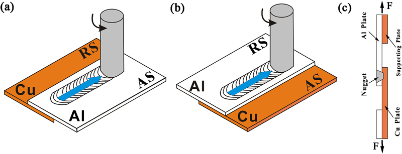
Schematic of FSW Al–Cu lap joints when Al plates were fixed on a advancing side (AS), b retreating side (RS) and c tensile shear specimen
Microstructural characterisation and analyses were carried out by optical microscopy, X-ray diffraction (XRD), scanning electron microscopy (SEM) and transmission electron microscopy (TEM), complemented by energy dispersive spectroscopy (EDS). Large transverse tensile specimens with a length of 100 mm and a width of 10 mm were machined perpendicular to the FSW direction. In this study, the tensile shear test was employed to estimate the tensile shear load of the FSW lap joint. Supporting plates at each end of the tensile specimen were added to maintain the joint interface parallel to the shear loading direction, as shown in Fig. 1c. For comparison, the tensile test of the Al parent plate with the same gauge width of 10 mm was also performed at an initial strain rate of 10−3 s−1. Because the strain state would be different in the two tensile test methods, such a comparison just provides a relative reference. The Vickers microhardness tests were performed on the cross-section perpendicular to the welding direction using 200 g of load for 10 s.
Results and discussion
Although two lapping modes were used in this study, the same cross-sectional microstructures were achieved in the nugget zones, as shown in Fig. 2. It is clear that the nugget zone consisted of two distinctly different parts, defined as NZ-1 and NZ-2 for the upper and lower parts respectively, in this study. The NZ-1 was pure Al material according to the EDS results from SEM, and the NZ-2 exhibited a composite structure consisting of Al matrix and Cu particles. Moreover, an obvious hook-like structure was observed at the interface of the retreating side and extended towards the advancing side. Actually, this is an inevitable defect for the FSW dissimilar lap joints between a hard and a soft metal, especially for larger pin plug depth.12 This should be related to the material flow process during FSW, and the materials were transported from the retreating to the advancing side behind the pin where the weld was formed. 21 21,22
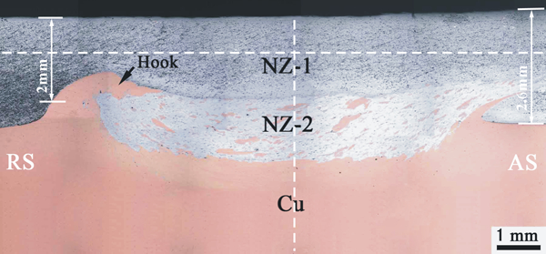
Cross-sectional macrograph of FSW lap Al–Cu joint: dash lines represent exact locations of hardness lines
Figure 3 shows the XRD result of the composite structure in the NZ-2 of the nugget zone. The characteristic diffraction peaks of the Al4Cu9 phase could be clearly observed, whereas the diffraction peaks of the Al2Cu phase were very weak, which was different from the observation in FSW Al–Cu butt joints, where the diffraction peaks of both Al2Cu and Al4Cu9phases exhibited similar intensities.20 This should be attributed to the special microstructure formed in the nugget zone of the lap joints, and this will be discussed in the next paragraph. A good metallurgical bonding between the Al matrix and the Cu particles is usually expected when a small number of IMCs formed at the interface.20
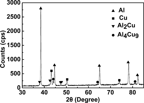
X-ray diffraction pattern of composite structure in NZ-2
The SEM backscattered electron image of the interface between the NZ-2 and the Cu bulk is shown in Fig. 4a. An obvious interface existed between the Al matrix and the Cu bulk, and a layered structure could be observed in the Cu bulk under the Al/Cu interface. Figure 4b shows the magnified view of the interface between the Al matrix and the Cu bulk. A continuous and uniform interface layer with a thickness of ∼1 μm, consisting of two discernible sublayers, could be distinctly observed. The sublayers near the Cu and Al sides should be Al2Cu and Al4Cu9 IMCs respectively, according to previous studies. 20 20,23
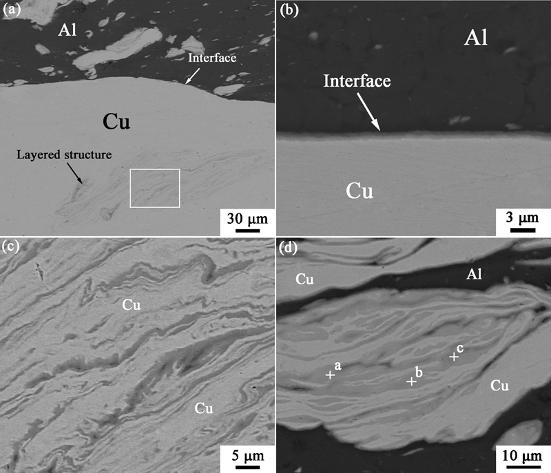
Scanning electron microscopy backscattered electron image of Al–Cu joint
The magnified view of the layered structure is shown in Fig. 4c. From the EDS analysis, the light and dark grey layers were pure Cu and Al–Cu IMCs respectively. Moreover, most Cu particles in the composite structure in the NZ-2 were also characterised by layered structures, as shown in Fig. 4d. Energy dispersive spectroscopy results indicated that the chemical composition at locations a, b and c in the dark grey layers was approximately equal to that of the Al4Cu9 phase. Therefore, these layered structures mainly consisted of Cu layers and Al4Cu9IMC layers, and this was in accordance with the EDS results. Because a limited amount of Al material existed in the layered structure, the Cu rich Al4Cu9 phase was easier to form in this case. Of course, few other Al–Cu IMCs might form in this layered structure due to the complex reaction between Al and Cu. 10 16 10,16,20
At the border of the layered structure near the Al matrix, a similar microstructure to the Al/Cu interface (Fig. 4b) was also observed. Besides, a few small Cu particles in the Al matrix might be transformed to Al–Cu IMCs during the FSW process. 10 16 10,16,20 The Al rich Al2Cu phase would form preferentially in these two cases, 20 20,23 resulting in weak characteristic diffraction peaks, as shown in Fig. 3. From the above results, most Cu particles in the NZ-2 consisted of layered structures, and Al4Cu9 was the main reaction products of the Al–Cu reaction in the layered structures during the FSW of Al–Cu lap joints. This accounted for the fact that strong diffraction peaks of the Al4Cu9 phase were observed in the XRD measurement.
Figure 5 shows the typical TEM microstructure of the Al matrix in the NZ-2. It is clear that an ultrafine grained structure was obtained in the Al matrix according to the TEM image and the corresponding electron diffraction ring pattern in Fig. 5a, and the grains could be refined to ∼100 nm (Fig. 5b).
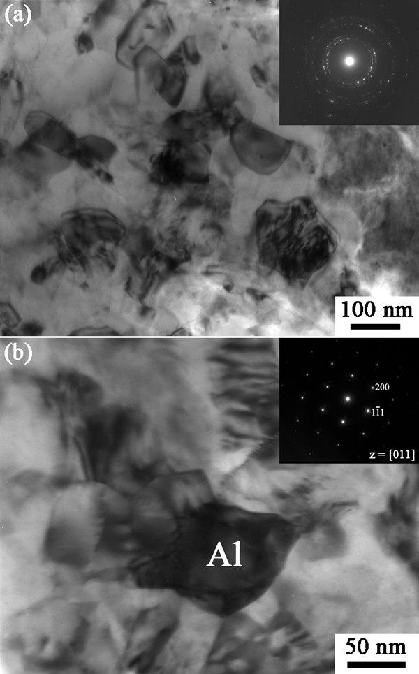
Images (TEM) showing a typical microstructure of Al matrix in NZ-2 and b magnified view of ultrafine Al grains and selected area diffraction pattern
Figure 6 shows the hardness profiles along the vertical line in the nugget centre and along the centreline across the NZ-1 on the transverse cross-section respectively (the measurement locations of the hardness profiles are schematically shown by dash lines in Fig. 2). It is clear from Fig. 6a that the hardness values of the Cu bulk and the NZ-1 were lower than those of the Cu parent (∼110 HV) and the Al parent (∼40 HV) respectively. Moreover, a low hardness region with the lowest hardness value of ∼30 HV in the heat affected zone (HAZ) was obtained in the NZ-1 (Fig. 6b). This indicates that obvious annealing softening occurred during FSW even at a lower rotation rate of 600 rev min−1. However, the hardness values in the composite structure (NZ-2) were much higher than those of the Al parent. The hardness value of the Al matrix in the composite structure was measured to be ∼60 HV, which was higher than that of the Al parent. This enhanced hardness of the Al matrix should be mainly attributed to the strengthening from the ultrafine grains. Moreover, the hardness of the layered structures was measured as high as 130 HV, which was higher than that of the Cu bulk. Previous studies indicated that the hardness of the Al–Cu IMCs was very high compared to that of the Cu parent, and the maximum hardness value could reach 760 HV.16 Therefore, the high hardness value of the layered structure originated mainly from the Al–Cu IMCs.
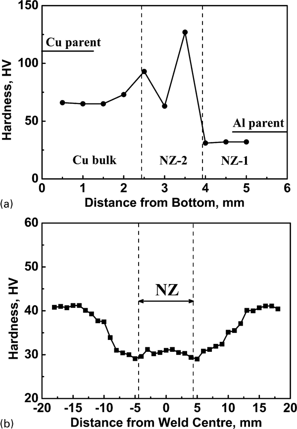
Hardness profiles along a vertical line in nugget centre and b centreline across NZ-1 on transverse cross-section
The tensile test results of the Al parent and the FSW lap Al–Cu joints are shown in Table 1. The joints all failed in the HAZ of the Al side, and the failure loads were different for the two FSW lap joints with different lapping modes, as shown in Fig. 1. When the Al plate was fixed at the retreating side, the failure load was 1940 N; however, the failure load was as high as 2680 N when the Al plate was fixed at the advancing side. Figure 7 shows the typical tensile shear fractured FSW lap Al–Cu joints for the two lapping modes. It can be seen from Figs. 2 and 7 that the thickness of the Al plate was significantly reduced above the hook-like structure on the retreating side. However, good metallurgical bonding was achieved on the Al/Cu interface at the hook-like structure due to the existence of a similar thin IMC layer. This exceeds the adverse effect of plate thinning at the hook-like structure on the mechanical properties of the lap joints. On the other hand, no effective bonding existed between the Al and Cu plates in the HAZ because this zone was basically out of intense stirring during FSW. Therefore, all the joints failed in the HAZ with the lowest hardness values for the two types of lap joints (Fig. 7), though the plate thickness in the HAZ was larger than that at the hook-like structure.
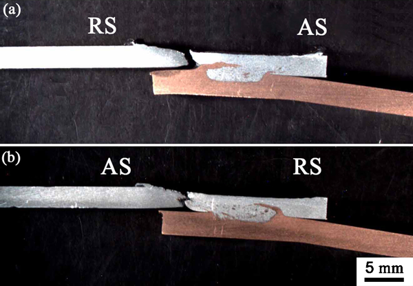
Tensile shear fractured FSW lap Al–Cu joints when Al plates are fixed on a RS and b AS
Tensile test results of Al parent and FSW Al–Cu lap joints
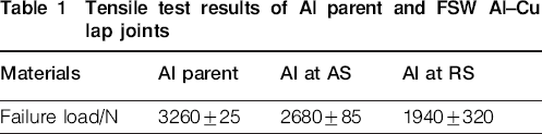
The thicknesses of the Al plates in the HAZ at the advancing and retreating sides in Fig. 2 were measured to be 2·6 and 2 mm respectively. It is clear that the thickness of the Al plate in the HAZ at the retreating side was considerably smaller than that at the advancing side, resulting in the lower failure load for the lap joint with the Al plate at the retreating side. Therefore, the lapping mode was also an important controlling factor in the FSW of dissimilar lap joints, and the soft material should be fixed at the advancing side in order to obtain better mechanical properties. The failure load was as high as 2680 N when the Al plate was fixed at the advancing side, which was higher than 80% of that of the Al parent. Abdollah-Zadeh et al. 10 achieved a similar failure load value (∼2700 N) in FSW lap Al–Cu joints; however, Al plates 4 mm in thickness were used. That is to say, enhanced tensile shear properties were obtained in this study. This is attributed to the following factors.
First, the formation of a thin, continuous and uniform IMC layer between Al and Cu enhanced the interfacial bonding, improving the mechanical properties of the FSW Al–Cu joints. Previous studies indicated that poor mechanical properties would be achieved in FSW dissimilar joints when excessive IMCs formed at the interface or in the nugget zone, especially at higher rotation rates.12, 13, 15, 16 Therefore, preventing the formation of excessive IMCs is extremely important in the FSW of dissimilar materials. However, a small number of Al–Cu IMCs was necessary for the metallurgical bonding between the Al material and Cu bulk/particles.17, 20 In this work, a small number of IMCs formed at the Al/Cu interface and in the nugget zone. The bonding strength of the Al/Cu interface was greatly enhanced by the formation of a thin, continuous and uniform IMC layer. For the Cu particles in the nugget zone, good metallurgical bonding with the Al matrix was also achieved through the IMC layers in the layered structures.
Second, a larger diameter pin produced a larger bonding area, thereby enhancing the bonding strength at the interface of the present FSW Al–Cu lap joint. Previous studies indicated that the FSW lap joints failed easily at the interface.10– 15 Crack propagation would be inhibited more effectively in the case of a larger bonding area at the Al/Cu interface during mechanical tests. Then, the lap Al–Cu joints hardly failed at the interface under a larger bonding area, and this was mainly decided by the pin diameter. Therefore, a larger diameter pin was beneficial to enhancing the mechanical properties of the FSW lap Al–Cu joints.
Third, the lower rotation rate used in this study produced a decreased annealing softening effect in the HAZ. The softening degree in the HAZ of the joints should be related to the heat input conditions, which were determined by the rotation rate and the traverse speed. Usually, the rotation rate that decided the maximum temperature played a more important role in the softening of the HAZ.18, 19 In this study, the hardness value in the HAZ of the Al material was ∼30 HV; however, the hardness value was reduced to ∼20 HV at a higher rotation rate of 1180 rev min−1, though a smaller FSW tool was used.10 Clearly, the softening effect decreased at the lower rotation rate in this study, resulting in enhanced mechanical properties.
Conclusions
In summary, the following conclusions are reached.
The 1060 aluminium alloy and commercially pure copper were successfully friction stir lap welded using a larger pin 8 mm in diameter at a low rotation rate of 600 rev min−1 and a traverse speed of 50 mm min−1. The nugget zone consisted of pure Al material and a composite structure in the upper and lower parts respectively.
The Al/Cu interface was characterised by a thin, continuous and uniform IMC layer, producing good interface bonding. Furthermore, good metallurgical bonding was achieved between the Al matrix and the Cu particles in the composite structure due to the formation of a small number of IMCs.
The FSW lap Al–Cu joints failed in the HAZ of the Al side, and the tensile shear load reached up to 2680 N when the Al plate was fixed on the advancing side. The hardness increased clearly in the layered structure due to the strengthening effect of the Al–Cu IMCs, which were mainly composed of Al4Cu9 phases.
Footnotes
Acknowledgements
This work was supported by the National Outstanding Young Scientist Foundation of China under grant no. 50525103 and the Hundred Talents Program of Chinese Academy of Sciences.