
Abstract
Welding system design includes selection of base metal, filler metal and process parameters for a given application. Integrated modelling has always been considered as a pathway to arrive at generic welding system solutions. Based on recent publications, arguments are made that generic solutions are indeed difficult. This is due to inability of these models to consider complex and transient boundary conditions imposed by field welding conditions. In lieu of generic solutions, design of invariant microstructure is suggested as an alternative approach.
Introduction
From the onset of fusion welding of steels by electric arc, there has been continued research to optimise microstructures and properties of heat affected zone (HAZ) and weld metal (WM) regions1 through experimentation. Variables for this experimentation include welding process, [e.g. shielded metal arc welding or laser welding], process parameters [e.g. speed, current], base metal composition [e.g. C, Si, Mn] and initial microstructure [e.g. ferrite or tempered martensite]. Furthermore, for a given process parameter range, fine-tuning of filler metal is done to optimise microstructure and properties. In the case of slag shielded welding processes [e.g. submerged arc welding or flux cored arc welding] optimisations of flux compositions are also needed. Above selection of base metal, filler metal and process parameter characteristics can be considered as welding system design. With introduction of new steel for a given application, the welding system design is repeated many times over. For example, let us consider aluminium containing transformation induced plasticity steels that have been introduced for automotive structure. On welding these steels, soft δ-ferrite forms in the HAZ and reduces their strength to traditional C–Mn steels. To minimise this softening, extensive process modifications have to be made.2 In another example, there is an ongoing research to minimise the creep property degradation in the HAZ of 9Cr–1Mo steels.3, 4 Although, there exists comprehensive heat and mass transfer models5 and computational thermodynamic and kinetic models,6 computational model based welding system design has not been adopted by the industries. In this paper, some of the challenges that limit the application of models for welding system design are discussed first. Based on these discussions, an invariant microstructure based weld system design is proposed as an alternative.
Current challenges
It is a daunting task to address a wide range of weldability issues (see Fig. 1) during design and production of welded structure. The welding system design should avoid all sorts of cracking including, weld solidification, liquation, ductility dip, stress relief and hydrogen assisted cracking. While guaranteeing crack-free welds, the weldments should achieve a microstructure that will perform as expected in (low or high temperature) service. To facilitate this microstructure control, the solidification (temperature gradient, solidification velocity), continuous heating and cooling (rates), post-weld heat treatment (temperature, time) have to be designed a priori. In summary, the weldability issues are related to dynamic changes in thermo-physical-chemical-mechanical properties during a given welding procedure. Various parameters that affect the welding system design are listed in Table 1. Even if we allow for some dependency between these parameters, the number of possible combinations is indeed challenging. It is physically impossible to evaluate these combinations using experimental trial and error approach. As a result, welding metallurgists settle for some local minima based on minimal design of experimentation and intuition based on legacy research. Consequently, these welding system designs are not transferable for a wide range of steels and applications. Owing to these facts, it is indeed not surprising, even after 100 years of arc welding invention, that the manufacturing community is still shackled by following problems:
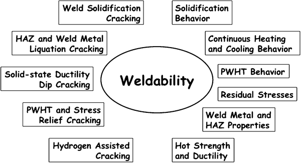
Schematic illustration of wide range weldability issues, to be considered during optimisation of advanced high strength steel welding, is presented. These requirements set up multivariant optimisation and conflicting targets, requiring compromise in certain cases
Independent and dependent parameters for welding system design*
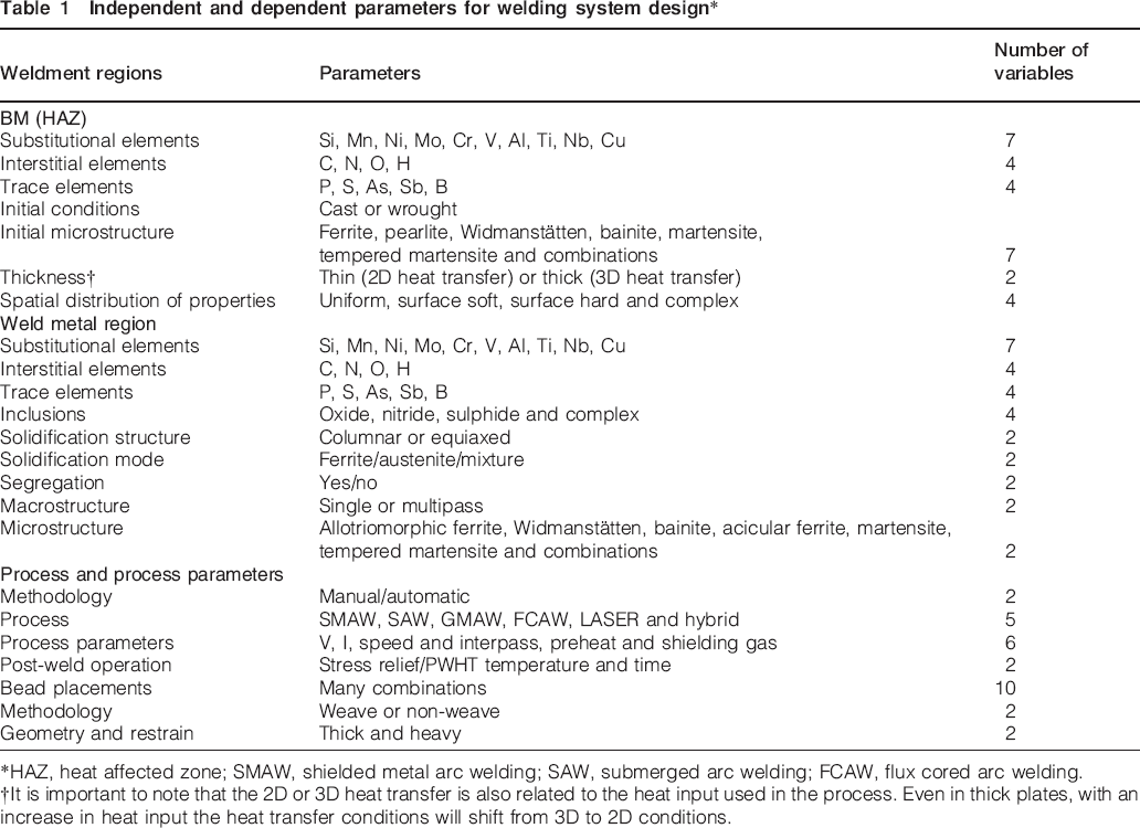
*HAZ, heat affected zone; SMAW, shielded metal arc welding; SAW, submerged arc welding; FCAW, flux cored arc welding.
†It is important to note that the 2D or 3D heat transfer is also related to the heat input used in the process. Even in thick plates, with an increase in heat input the heat transfer conditions will shift from 3D to 2D conditions.
welding solutions are expensive and non-optimum
deployment of new steels is delayed
nagging scatter in the weldment properties are usually considered as norm.
Some of these challenges are briefly discussed with published examples. 7 7,8
Example of challenges in HAZ property optimisation
Recently, a blast resistant steel (BA-160) was developed for Navy applications, using multiscale modelling methodologies. 9 9,10 The BA-160 steel exhibits optimum combination of yield strength (1103 MPa) and Charpy toughness (>176 J at 30°C) due to nanoscale carbides and copper precipitation within a low carbon martensitic matrix. The hardness of this steel after the heat treatment is ∼400 HV. The steel was considered weldable since it contained low carbon11 concentration (<0·06 wt-%). This hypothesis is valid since the low carbon martensite may not lead to hydrogen induced cracking. However, responses of this steel to other weldability issues (see Fig. 1) were not considered during the design stage. Therefore, weldability investigations of this steel were performed by Yu et al. 7 and Caron.11 Reheat cracking tests and HAZ thermal simulations were performed using a Gleeble thermomechanical simulator. In reheat cracking test, the samples were subjected to two thermal cycles. In the first thermal cycle, the samples were heated to 1300°C and cooled at a given rate. The cooling rate is controlled by setting the time taken to cool from 800 to 500°C (Δt800–500°C) to be 20 s. This produces a sample typical to that of a coarse grained HAZ region, relevant to low heat input welding process. Then the samples were reheated to different temperatures and held isothermally. This step simulates a typical post weld heat treatment schedule. Under these conditions, the samples were strained at a rate of 0·5 mm min−1. Interestingly, BA-160 steels showed excellent reheat cracking resistance compared to other Navy steels.11 In the next step, the HAZ strength was evaluated by thermal simulations. The samples were heated to different peak temperature Tp and cooled to room temperature at a given cooling rate, i.e. Δt800–500°C = 45 s. This cooling rate is similar to the conditions experienced HAZ of high heat input welds. Under these conditions, when TP⩾900°C, BA-160 steels exhibited softening (see Fig. 2). In addition to softening in the HAZ of BA-160 steel, there was anomalous hardening in the samples heated to a peak temperature of 750°C. This temperature corresponds to an intercritically reheated region, since the Tp is between Ac1 (660°C; austenite fraction = 0) and Ac3 (810°C, austenite fraction = 1). Application of phase transformation models to the above problem suggested only a monotonous softening in the HAZ as a function of peak temperature. 7 7,11 Therefore, fundamental reasons for the above hardening and softening were investigated with electron back scattered diffraction (EBSD) and local electrode atom probe characterisation.
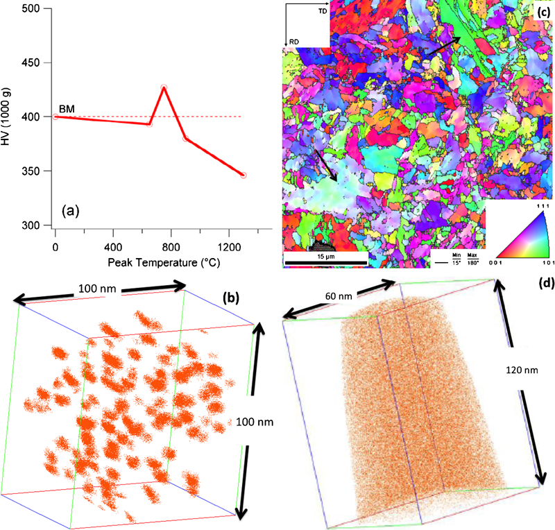
Summary of results from HAZ thermal simulation of BA-160 steel
On heating the BA-160 below Ac1 temperature, the carbides and copper precipitates are expected to coarsen. However, this rate of coarsening, depending upon the time spent at high temperature, may not be significant during a typical weld thermal cycling. As expected, the drop in hardness on heating the steel to 650°C was minimal (see Fig. 2). The measurements from local electrode atom probe showed copper precipitate distribution similar to that of base metal (see Fig. 2b). On heating above Ac1 temperature, as the austenite forms, the carbide and copper precipitates dissolve rapidly. This is mainly due to increased solubility of copper in the austenite phase. In agreement with this hypothesis, the copper atom maps of samples after thermal simulation with Tp = 900°C and 1300°C7 (see Fig. 2d) showed uniform distribution. As a result, the samples are expected to show a monotonous decrease in hardness. In order to understand the hardening of intercritically heated samples, EBSD analyses were performed. The analyses showed very small martensite packet size (see Fig. 2c). This is attributed to small austenite grain size that is achieved on heating to 750°C. Owing to the constraints of the austenite grain boundaries, the displacive growth of martensite is limited and henceforth a smaller packet size. It is well established that the strength of martensite increases with a decrease in martensite packet size. 7 7,12 This phenomenon is related to grain boundary strengthening mechanism. This additional strengthening compensates for the reduction in strength due to the dissolution of precipitates in the matrix. However, on heating the samples to 1300°C, rapid austenite grain growth occurs. With large austenite grain sizes, the martensite packet size becomes larger and looses the grain boundary strengthening. As a result, the softening is observed in samples heated to 1300°C. Based on these results, Yu and Caron13 have proposed an idea to regain the strength by leveraging multipass weld thermal cycles. Their idea relies on re-precipitation of copper and carbides within the martensite during reheating. The above results show complex interplay between micro- and nano-scale strengthening in these steels.
It is important to note the above investigation relied on extensive experimentation and characterisations, as well as, the suggested solution may not be optimal. Furthermore, the suggested solution was not obtained a priori with integrated process models. This is indeed expected since none of the published process models can predict all the phase transformation events including austenite nucleation, austenite grain growth, martensite packets formation, precipitate coarsening, dissolution and re-precipitation, as a function of complex thermomechanical histories.
Examples of challenges in weld metal microstructure optimisation
Upon optimisation of base metal, the next challenge is to design weld metal composition with optimum strength and toughness.14 To achieve this goal, extent of acicular ferrite in the weld metal region has to be maximised by modifying weld metal composition. For the above need, a well established weld microstructure model15 was coupled with an optimisation programme. The above methodology and results have been published already.8, 16 The data to be presented in this paper are based on a hybrid optimisation scheme. In this scheme, the algorithm uses either downhill simplex or genetic optimisers based on the need. This need is based on the analyses of results from previous iterations. To arrive at local minima faster, the downhill simplex method may be used in the beginning. However, under complex topographies of solutions, genetic optimisers will be leveraged. This selection of proper schemes had been implemented using a pointer technology within a commercial software (Epogy by Engineous Software Inc., is currently acquired by SIMULIA). The optimisation target was set to achieve 80% acicular ferrite during single pass shielded metal arc welding for a given heat input (welding current 170 A, voltage 21 V and speed 0·0035 m s−1] of 1 kJ mm−1. Allowable maximum concentrations of Si, Mn, Ni, Mo, Cr and V were capped at 2 wt-%. Similarly, the maximum carbon concentration was capped at 0·4 wt-%. It is also assumed that the weld metal region will contain titanium rich inclusion to promote nucleation of acicular ferrite. The optimisation results are shown in Fig. 3. The results show that a large number of weld metal compositions will lead to 80% acicular ferrite. All these candidate compositions have higher nickel (>1·5 wt-%) and manganese concentrations (>1·0 wt-%). Surprisingly, calculations starting with different initial composition set gave different weld metal composition for the same requirement.8 The above results are in agreement with extensive data published by Evans and Bailey.17 The above modelling exercise demonstrated that for a given cooling rate, the extent of acicular ferrite formation is related to the topology of continuous cooling transformation diagram.
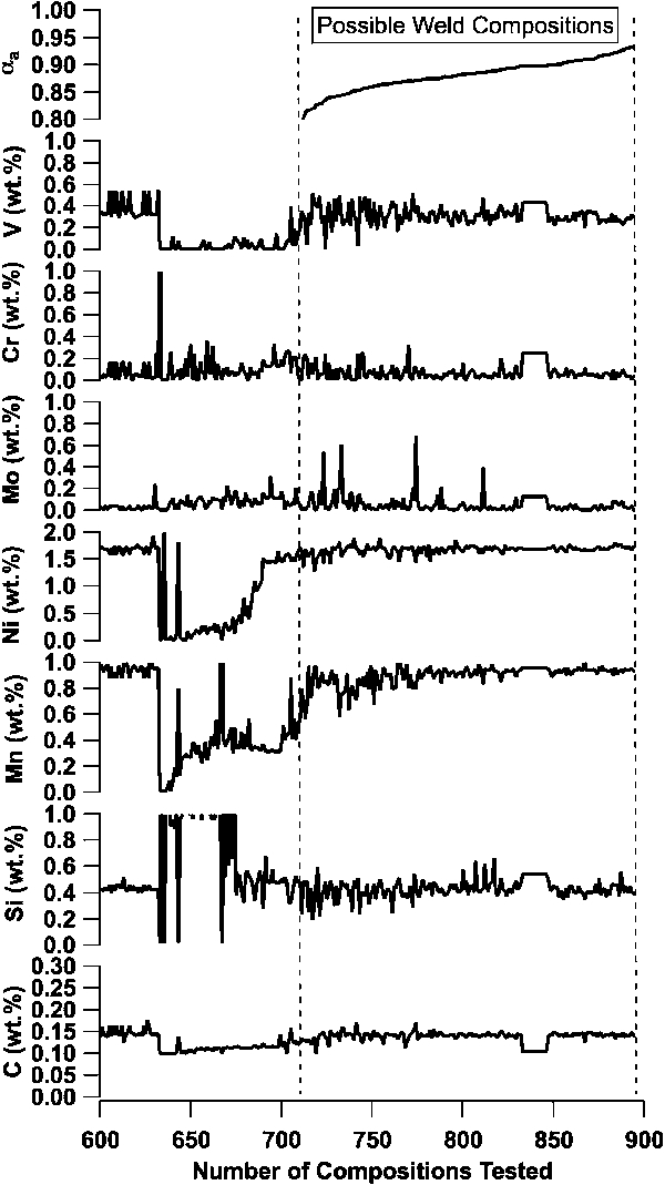
Overview of WM compositions selected by an optimisation algorithm, providing 80% or more acicular ferrite in the as welded deposit, show non-unique solutions. The above calculations were performed by coupling commercial optimiser software with phase transformation model
It is important to note that the above model based optimisation exercise cannot be extended to multipass weld metal region. Under multipass welding conditions, spatially varying peak temperatures, heating rate and cooling rates are expected to produce a large microstructural heterogeneity. The microstructural heterogeneity can be induced by a simple change in weaving practice.18 This microstructural heterogeneity can lead to a wide range of scatter in strength and toughness (see Fig. 4). The observation of three peaks in the toughness distribution has been rationalised based on the stochastic placement of Charpy v-notch (see the inset of Fig. 4) with reference to the geometry of an all weld metal test specimen, along the length of the weld. The higher values (>250 J) are related to conditions when the notch is placed in a region that contains predominantly acicular ferrite microstructure. In most of the testing conditions, the notch is placed in the middle of the multipass regions thereby sampling regions with acicular ferrite and fine reheated ferrite microstructures. This condition leads to an acceptable toughness (162 J) values suggested by the nominal peak. Under rare conditions, the notches may be placed close to a local brittle zones created by the weaving practice. Unfortunately, this leads to a population of test data with low toughness, as indicated by the peak at 24 J.
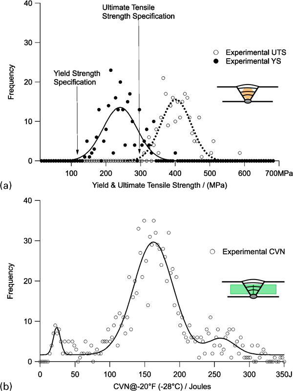
Frequency distribution of measured mechanical properties collected over many years from E7018 weld deposits under similar conditions
Currently, the integrated models are not capable of describing such spatial variations in properties, since the microstructure models15 assume a steady state thermal cycle. Ability to describe the spatial variations requires accurate description of bead placement and welder practice under field welding conditions. This inability to predict subtle and often large microstructural sensitivity to boundary conditions imposed by field welding conditions suggests limited use of these models by industries. Unless an innovative technique to predict and control the above heterogeneity is developed, the deployment of integrated process models to industrial applications will always be met with skepticism. Therefore, we need a revolutionary approach for welding system design. In the sprit of this special issue for developing radical ideas related to welding, the author has made some recommendations below.
Invariant HAZ and WM microstructure
To reduce the property scatter in HAZ and WM, the microstructures in these regions have to be designed to be invariant. In other words, the microstructure in HAZ should be the same before and after welding. The microstructure evolution in the WM has to the same, irrespective of any change in weld cooling rate or multiple thermal cycles (see Fig. 5a). The above hypothesis is explained below.
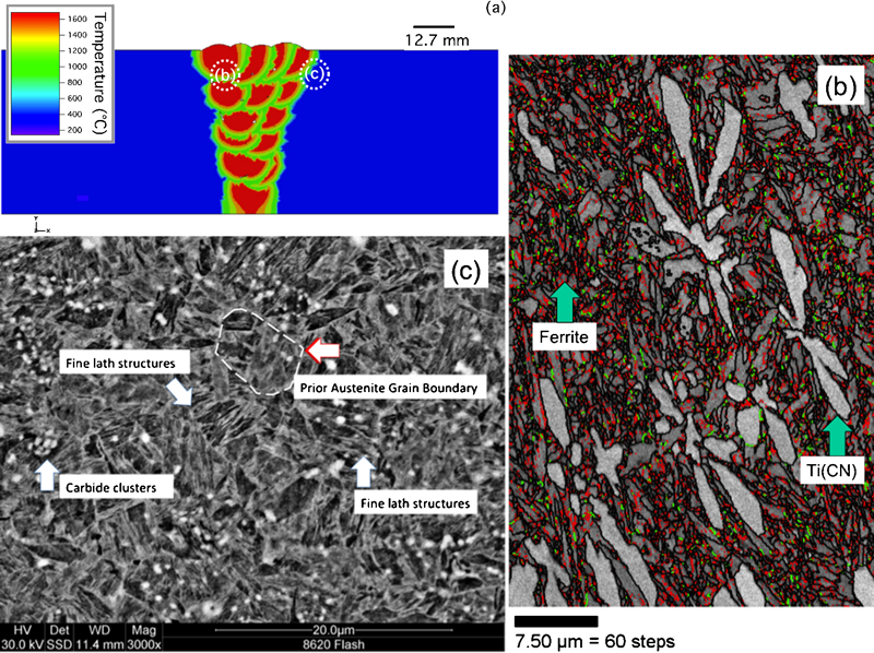
Hypothetical proposal for inducing invariant microstructures in WM and HAZ
In the case of the HAZ, the steel matrix should remember its initial microstructure and should transform back to the same microstructure after heating and cooling. This idea may appear to be far fetched due to the following fact. It is impossible to stop the reverse transformation of ferrite to austenite during heating and a wide range of austenite to ferrite transformation products during cooling. Nevertheless, some of the recent publications provide some plausible pathways:
experimental evidence for HAZ microstructure memory effect is emerging in Cr–Mo steel welds with boron addition. Presence of microstructure memory effect is argued based on the similar austenite grain size and shape, as well as, martensite orientation,19 before and after thermal cycling. The memory effect is being rationalised by displacive transformation on heating (α −>γ) and cooling (γ −>α) conditions
memory effect can also be engineered by distributing Cr-rich carbides in the initial room temperature microstructure. These carbides on heating to austenite phase field exhibit sluggish dissolution.20 Recent work by Lolla et al. 21 shows that by rapid heating of Cr containing steel (>400°C s−1), the dissolution of cementite is stifled. With limited dissolution, the carbon content of the austenite phase remains lower than the bulk concentration of the overall steel. On cooling, this low carbon austenite transforms to mixed (bainite+martensite) microstructure (see Fig. 5c) for a wide range of steels.22 Interestingly, these flash processing conditions also lead to similar microstructure irrespective of the bulk carbon concentration of the steel.23
In the case of WM, invariant microstructure evolution can be forced by limiting the extent of solid state transformations after weld solidification. For example, fine delta-ferrite equiaxed regions (<1 μm) were attained by heterogeneous nucleation on titanium carbonitrides (see Fig. 5b) in liquid steel.24 It is noteworthy that such a microstructure was attained by laser surface alloying process. The copious formation of titanium carbonitrides was promoted by intentional dissolution of nitrogen in to the liquid melt pool. It is important to note that such engineered inoculation of weld metal is not a new idea. Villafuerte et al. 25 have demonstrated the feasibility of heterogeneous equiaxed nucleation of ferrite on TiN, in lieu of the columnar grain growth in welds.
This welding system design for invariant WM and HAZ microstructure needs to be moderated by following constraints:
the design of invariant microstructures is not trivial. Although the example shown in Fig. 5b was derived by computational thermodynamic and kinetic calculations, targeted experimental work was necessary to validate and scale up
second constraint is related to the welding system design that minimises the distortion and residual stress. In this regard, some of the modelling tools for heat and mass transfer,26 base metal9 and filler metal15 can be leveraged
third constraint is the reduction of welding system cost while satisfying the invariant microstructure criteria. The author believes that it is indeed possible to control the microstructure and increase the productivity by leveraging the arc-laser hybrid welding systems. For example, using heat and mass transfer models,27 the cooling rates can be controlled during solidification and solid state transformation to induce invariant microstructure
the final constraint is related to mechanical properties. The invariant microstructure may not meet the desired low temperature or high temperature properties. Therefore, we need to able to predict the impact of invariant microstructures on properties. In this regard, the author believes that the value of integrated process modelling28 is immense.
Based on the above discussions, the author of the paper is optimistic that the welding metallurgists will leverage the integrated weld process models to induce invariant microstructures in WM and HAZ to minimise scatter in properties, within a decade.
Concluding remarks
Design of welding system that involves selection of base metal, filler wire and welding process parameter still relies on trial and error experimentation. Often, the use of integrated process modelling has been considered as a pathway to minimise the experimental scope of optimising the properties of HAZ and WM regions. However, recent weldability research from BA-160 steels shows that there are deficiencies in the integrated process models to predict the nano- and micro-scale phase transformations concurrently. In addition, optimisation exercises for weld metal regions show no unique weld metal composition for maximisation of acicular ferrite. The response of weld metal microstructures to multipass welding may also not lead to any generic solution. To address these challenges, a radical approach to induce invariant microstructure in both WM and HAZ is proposed as a way to optimise the weldments.
Footnotes
Acknowledgements
The author acknowledges that the hypotheses presented in this paper are based on many years of discussions and collaboration with world-renowned researchers in welding metallurgy, including Professor H. K. D. H. Bhadeshia (University of Cambridge), Professor T. DebRoy (Pennsylvania State University), Dr S. A. David (ORNL), Dr J. M. Vitek (ORNL), Dr M. L. Santella (ORNL) and Ms Marie A Quintana (Lincoln Electric). In addition, the author acknowledges that the welding system design examples presented in this paper are based on the collaborative research with Professor J. C. Lippold (OSU), Professor G. B. Olson (Northwestern University), Professor D. Seidman (Northwestern University), Dr M. Murugananth (Wollongong University), Dr J. Caron (Haynes International), Mr Xinghua Yu and Mr Tapasvi Lolla (OSU, PhD students).