
Abstract
Underwater friction stir welding (FSW) has been demonstrated to be an effective method to improve the mechanical properties of joints. To illuminate the characteristics of underwater FSW, the microstructural evolution and its effect on mechanical performance of an underwater joint were investigated in the present paper. The weld nugget zone (WNZ) is characterised by the homogeneity of refined grain structures in the direction of thickness. The precipitate deterioration is gradually strengthened from the heat affected zone (HAZ) to the WNZ. The dislocation movement featured by different types of grain boundaries suggests that continuous dynamic recrystallisation has occurred in the WNZ during FSW. The evolutions of strengthening precipitates and grain structures have significant influence on hardness distributions and the tensile fracture features of the underwater joint.
Introduction
With regard to the friction stir welding (FSW) of heat-treatable aluminium alloys, the welding thermal cycles tend to cause a local softening in the joints through coarsening or dissolving the strengthening precipitates, which results in a degradation in joint properties.1– 4 In order to improve the mechanical performance of the joint, the post-welding heat treatment was adopted by several researchers.5– 7 Although good compensating results can be obtained, such an approach is often too costly from an industrial point of view. In recent years, in-process cooling has been proposed as an effective method to solve the local softening problems in the FSW of heat-treatable aluminium alloys. The basic idea of this approach is to exert an external liquid cooling on welding samples during FSW with the aim of reducing the thermal flow into the joints. Fratini et al. 8, 9 performed FSW experiments with water flowing on the top surfaces of samples during the welding process. It was found that the tensile strength of the joint can be improved to some extent by the water cooling effect. In order to take full advantage of the heat absorption capacity of water, the present authors10 conducted underwater FSW of 2219-T6 aluminium alloy, during which the whole workpiece was immersed in the water environment. The results indicated that the tensile strength of the underwater joint was higher than that of the normal joint. Previous investigations have highlighted the advantages of in-process cooling for strength improvement of joints. However, these studies were mainly related to the mechanical characteristics of the cooled joints, and the microstructural evolution in the cooled joints has not been sufficiently focused until now. It is known that the mechanical properties are essentially dependent on the microstructures. In this sense, clarifying the microstructural characteristics of the cooled joint is of great significance to better understand the in-process-cooling FSW, and it will be extremely important if this process is to be optimised in the future. In order to do so, a 2219-T6 aluminium alloy was underwater friction stir welded in the present paper, and the focus was placed on the microstructural evolution in different zones of the underwater joint in terms of grains, precipitates and dislocations. The influence of microstructures on the mechanical properties of the joint was also studied and discussed.
Experimental procedure
The base material (BM) used in the experiment was a 7·5-mm-thick 2219-T6 aluminium alloy, whose chemical compositions and mechanical properties are listed in Table 1. The plate to be welded was machined into rectangular welding samples with dimension of 300 mm long by 100 mm wide. After cleaned by acetone, the samples were clamped to the backing plate in a vessel, and then the water at room temperature was poured into the vessel to immerse the top surface of the samples. Underwater FSW was performed using an FSW machine (FSW-3LM-003) along the longitudinal direction (perpendicular to the rolling direction). The conical welding tool size and welding parameters are listed in Table 2.
Chemical compositions and mechanical properties of 2219-T6 aluminium alloy
Tool size and welding parameters used in experiments
After welding, the joint was cross-sectioned perpendicular to the welding direction for metallographic analyses. The cross-section of the metallographic specimen was polished using a diamond paste, etched with Keller's reagent and observed by an optical microscope (OM, Olympus-MPG3).
The precipitates and dislocations were observed on sections parallel to the welding line at the weld mid-thickness by transmission electron microscopy (TEM). The sections were first machined and manually polished down to a thickness of 100 μm. The final thickness reduction was acquired by electropolishing with a HNO3 solution (HNO3 30% in volume in methanol at −35°C under 18 V). The diameter and thickness of the precipitates were determined by image analysis performed on [0 0 1] Al zone axis orientation.
Prior to tensile tests, the cross-sections of the transverse rectangular tensile specimens were polished with a diamond paste, and then Vickers hardness profiles were measured at the mid-thickness across the weld nugget zone (WNZ), the thermomechanically affected zone (TMAZ), the heat affected zone (HAZ) and partial BM. The load was 4·9 N for 10 s, and the Vickers indents with a spacing of 1 mm were also used to determine the strain distributions of the joint in tensile test. The room temperature tensile test was carried out at a crosshead speed of 1 mm min−1, and the mechanical properties of the joint were evaluated by three tensile specimens cut from the same joint.
Results and discussion
Grain morphology
Figure 1a shows the transverse cross-section of the underwater joint, where RS and AS represent the retreating side and the advancing side, respectively. Figure 1b–d shows the recrystallised grain structures extracted from the upper, middle and lower parts of the WNZ along the weld centreline. The upper, middle and lower parts are at a distance of 1·25, 3·75 and 6·25 mm from the weld top surface respectively. It can be seen that the size of the refined grains is nearly the same in the three parts, indicating the homogeneity in microstructures in the thickness direction. This is different from the normal joint where the WNZ generally exhibits a decrease in grain size from the upper part to the lower part.11– 13 A significant feature of underwater FSW is that the workpiece is entirely immersed in the water environment during the welding. Therefore, a large amount of heat can be dissipated not only from top surface but also from lateral and bottom surfaces of the samples under the integral cooling effect of water, leading to a more uniform thermal action and thus a similar grain structure in the thickness direction of WNZ.

Grain morphologies in different zones of joint
The grains are highly extruded and elongated in the TMAZ on the AS (Fig. 1e), resulting in a sharper WNZ/TMAZ interface. In contrast, the WNZ/TMAZ interface is rather unclear on the RS of the weld (Fig. 1f). The HAZ, not disturbed mechanically by the welding tool, is still characterised by coarse grained structures (Fig. 1g).
Precipitate evolution
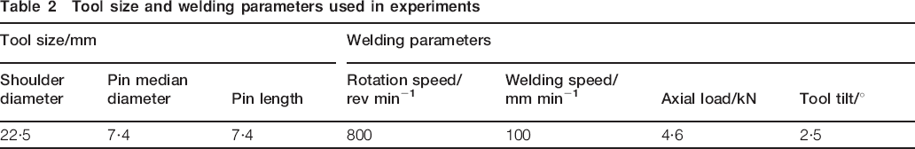
Figure 2 displays the precipitate evolution in different zones of the joint. The BM contains a high density of precipitates with plate morphology (Fig. 2a), which are identified as the meta-stable θ′ phases according to the electron diffraction patterns from this zone (Fig. 2b). The partial coherency of the θ′ precipitates with the matrix is responsible for the good mechanical properties of this alloy. The HAZ experiences precipitate coarsening in contrast to the BM (Fig. 2c). The comparison of Fig. 2e and Fig. 2c shows that the TMAZ contains larger θ′ precipitates than the HAZ, reflecting an improvement in precipitate coarsening level. The electron diffraction patterns (Fig. 2f) exhibit weak reflections from the θ′ precipitates, resultant from the decrease in precipitate density in the TMAZ. Additionally, some block-shaped equilibrium θ phases are observed in this zone, which are transformed from the meta-stable phases in the welding thermal cycles. In the WNZ, the meta-stable phases completely disappear and only a few θ precipitates are remained (Fig. 2g). As a result, no θ′ precipitate reflections can be observed from the corresponding electron diffraction patterns (Fig. 2h).
a, c, e, g precipitate distributions in BM, HAZ, TMAZ and WNZ respectively, b, d, f, h corresponding electron diffraction patterns to Fig. 2a, c, e and g
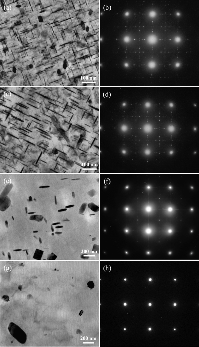
Figure 3 shows the diameter and thickness of the θ′ precipitates in different zones of the underwater joint. The precipitate diameter grows faster than the precipitate thickness from the BM to the HAZ. This confirms that the precipitates tend to grow preferentially in the low coherency direction of the longest axis with increasing temperature level. In the TMAZ, the precipitate thickening becomes significant for higher welding temperature. Furthermore, the precipitates display relatively large error bar in thickness compared with the BM and the HAZ, indicating a more widespread size distribution. Generally, the thinner precipitates also exhibit a smaller diameter, as seen from Fig. 2e. Associated with the lower precipitate density in the TMAZ, it is believed that precipitate dissolution should also occur during the precipitate coarsening. In the WNZ, the meta-stable phases have nearly all been dissolved into the matrix and only the equilibrium θ phases are remained.
Size of θ′ precipitates in different zones of joint
Dislocation structures and recrystallisation mechanism
A large number of deformed grains from BM are found to contain high density dislocations with a network structure (Fig. 4a). In the TMAZ, the low density dislocations, occasionally presenting the recovered structure, indicate that the recovery phenomenon has occurred in this zone during FSW (see Fig. 4b).

Dislocation structures of a BM and b TMAZ
The WNZ exhibits an improved dynamic recovery (DRV) and recrystallisation (DRX) in contrast to the TMAZ. However, the dislocation densities within the neighbouring grains are different from each other (Fig. 5a), suggesting that the grains are at different stages of DRV and DRX. Figure 5b–d shows different types of substructures in the WNZ. As shown in Fig. 5b, the grain boundary is characterised by one light central band and two darker border bands, which is a typical feature of the non-equilibrium grain boundary with a long range stress.14 The long range stress tends to absorb dislocations generated by plastic deformation. Pile-up of dislocations near the non-equilibrium grain boundary characterises this process evidently. A coarsened non-equilibrium grain boundary and a dislocation wall can be seen in Fig. 5c; and a few dislocations exist near the grain boundary, implying that further DRV with dislocation polygonisation occurs in the grains. In Fig. 5d, an equilibrium grain boundary composed of multilayers is formed. However, a large amount of dislocations, pinned by small precipitates, still exist near the grain boundary, indicating that dislocations are continuously generated under the tool stirring action during FSW.
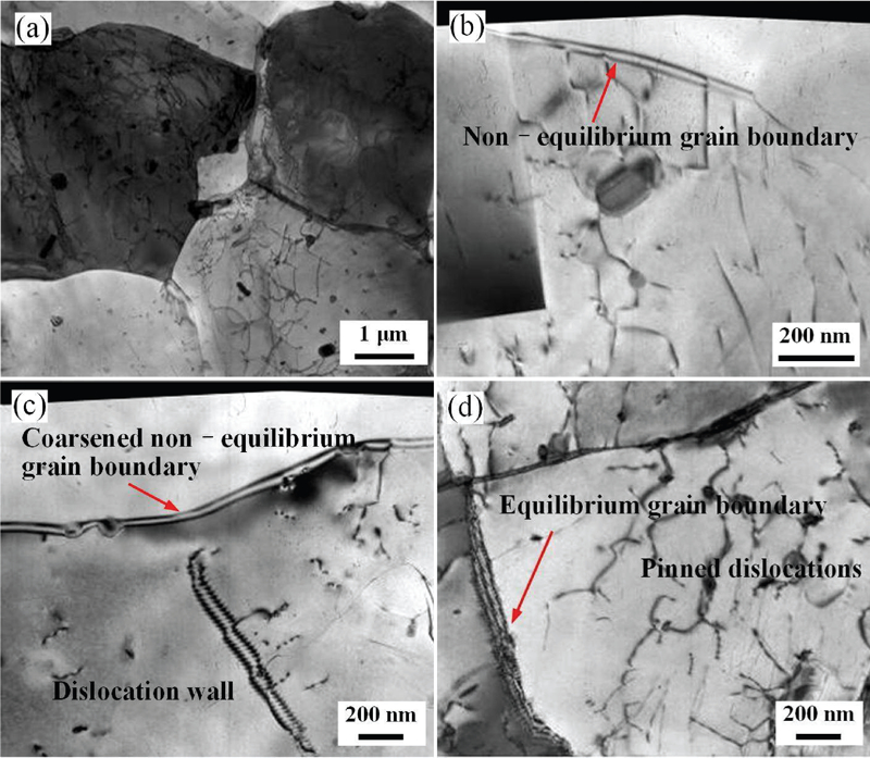
Micrographs (TEM) of WNZ
Actually, the different types of grain boundaries mentioned above can be used to feature the dislocation movement process. The generated dislocations first rearrange to form the non-equilibrium grain boundaries through DRV. By repeatedly absorbing dislocations, non-equilibrium grain boundaries are coarsened and dislocation walls are formed. With further plastic deformation, dislocations are continuously generated and introduced to the grain boundaries to accommodate the stain incompatibility between neighbouring grains until the high angle equilibrium grain boundaries are formed and the long range stress disappears. In nature, this dislocation movement process typically characterises the continuous dynamic recrystallisation (CDRX),15– 18 demonstrating that CDRX occurs in the WNZ during FSW. The water cooling effect produces a rather large strain gradient around the tool pin, and thus the ‘frozen’ microstructures in different stages of DRV and DRX can clearly record the CDRX process.
Influence of microstructures on joint properties
The microstructural evolution can also be reflected from the mechanical performance of the joint. Solid solution strengthening, precipitation strengthening, grain boundary strengthening and dislocation strengthening are the known mechanisms that contribute to the joint properties.3, 19– 21 Regarding the precipitate hardened aluminium alloys, the mechanical properties are mainly dependent on the strengthening precipitates. Although the contributions of the other three factors to mechanical properties are limited, they also have some importance as the precipitation strengthening effect nearly disappears.
The precipitate evolution in different zones of the joint creates a softening region with lower hardness than the BM (see Fig. 6). For this reason, the tensile strength of the underwater joint, 341 MPa, is still lower than that of the BM, but is higher than that of the normal joint, 324 MPa. From HAZ to WNZ, although the precipitate deterioration is gradually strengthened, as described in Fig. 2, the hardness does not decrease consistently but presents a slight increase towards the WNZ. This should be attributed to the grain refinement and the enhanced solid solution strengthening effect, while the precipitates and dislocations exert little strengthening effect in the WNZ (Figs. 2 and 5). Therefore, the lowest hardness is located in the TMAZ adjacent to the WNZ on either side of the weld. This is different from the normal FSW, in which the lowest hardness of the joint is usually located in the HAZ.7, 22, 23 The lowest hardness shift from the HAZ to the TMAZ is important to the impact of overall mechanical properties of the FSW joint. In this case, the weakest location of the FSW joint is just the TMAZ instead of the HAZ. Accordingly, improving the mechanical properties of the TMAZ is crucial to the optimisation of underwater FSW process.
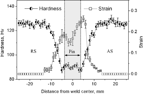
Distributions of hardness and strain across joint
The overall elongation reaches 7·6% for the present underwater joint. However, a heterogeneity in ductility across the joint can be observed from the stain distributions, as shown in Fig. 6. Apparently, plastic deformation tends to be localised in the softening region during tensile test. Furthermore, the location with lower hardness is usually characterised by a larger strain value. The maximum strain location, in which the fracture occurs during tensile test, is consistent with the lowest hardness region. It is interesting to find that the fracture location is on the AS rather than on the RS, although the lowest hardness is lying on both sides of the weld. The reason for this is that the WNZ/TMAZ interface is sharper on the AS than on the RS (see Fig. 1e and f). During tensile test, the sharper interface facilitates a mismatch material deformation between WNZ and TMAZ, and thus the microcracking tends to form first in the weakest location near the sharp interface.
Conclusions
From this investigation, the conclusions of significance are drawn as follows.
The WNZ is of homogeneity in grain size in the thickness direction of the weld, and the WNZ/TMAZ interface is sharper on the AS than on the RS.
The HAZ exhibits a coarsening of meta-stable precipitates compared with the BM. In the TMAZ, some meta-stable θ′ precipitates are coarsened, and the others are transformed into equilibrium θ phases or dissolved into the matrix. In the WNZ, the precipitates are mostly dissolved into the matrix and only a few stable precipitates are remained.
Partial recovery exists in the TMAZ and continuous dynamic recrystallisation occurs in the WNZ during the FSW. The different dislocation structures are lying within the neighbouring grains in the WNZ.
The precipitate deterioration is strengthened from HAZ to WNZ, but the grain refinement and solid solution strengthening leads to a slight increase in the WNZ hardness. The weakest location of the underwater joint is in the TMAZ adjacent to the WNZ/TMAZ interface on either side of the weld, but the tensile fracture location of the joint is only on the AS of the weld.
Footnotes
Acknowledgements
The authors are grateful to be supported by the National Basic Research Program of China (973 Program, no. 2010CB731704) and by the National Science and Technology Major Project of China (no. 2010ZX04007-011).