
Abstract
Typical flash weld defects are divided into metallurgical and mechanical defects. The metallurgical defects, which also include defects known as flat spots, penetrators and oxide inclusions, are difficult problems and develop during flashing action. The appearances and differences of flat spots, penetrators and simple oxide inclusions in flash welds are determined in this study based on literature review and experimental studies with three different steel grades. It was concluded on the basis of experimental studies that the chemical compositions of flat spots and oxide inclusions are the same, and the main difference between them is their appearance: flat spots are fracture surfaces nucleated from oxide inclusions, but simple oxide containing slags can appear also in non-fractured surfaces.
Introduction
Flash welding is a resistance welding process, which enables high production rates and rapid welding cycles with reliable joint quality. Since any filler metal is not used, the seam is basically developed from pure base metal. The flashing and upsetting actions assure that all the impurities are extruded out from the developing joint. Still, when proper welding conditions are not maintained or the process suffers from errors, different weld defects may develop as well as in any other welding process. Depending on the origin and their presence, the defects associated with flash welding are generally divided into two categories: mechanical and metallurgical defects. 1 1,2
The mechanical defects are typically detected with visual inspection since they are often caused by insufficient clamping and upsetting forces or misalignment of workpieces. These defects are easy to detect and eliminate without considerable effort with process control and regular maintenance.
The more interesting and also more troublesome defects in flash welds are, however, the metallurgical ones. These discontinuities are difficult to detect and often need destructive testing to be revealed. Metallurgical defects are more or less individual, and thus, the generation of a certain defect type may depend, e.g. on certain welding parameter or welding conditions. Metallurgical discontinuities in flash welds may not always be defects, and the determination depends greatly on the quality requirements of the weld. For example in endless rolling, which is basically a production method where austenised billets are joined with flash welding in the beginning of the rolling line, the quality requirements for weld purity are very high. This is because the flash welded endless billet is rolled to a diameter of just a few millimetres and after that possibly upgraded to even thinner drawn wire, so even small discontinuities may break the wire during the final rolling or wire drawing.
The origins and generation conditions of metallurgical defects, like voids, burns or cracks, are quite well known, but less information is available about generation conditions and outward appearance of flat spots and penetrators and even about the simple defects like oxide inclusions in flash welds. These three types of metallurgical discontinuities have been repeatedly mentioned in the literature and scientific studies, thus seeming to be quite common metallurgical defects in flash welds. Suggestions for these kinds of or similar weld problems are mentioned in Refs. 1–17. However, the distinctions between these three defect types are often unclear, and any proper definition of their concrete appearance is not easy to find. Especially, figures of flat spots and oxide inclusions or their surroundings are seldom presented, although in the literature, they are well known non-metallic defects in flash welds. In this study, the three types of metallurgical discontinuities are discussed in association with literature survey and results of experimental studies made with flash welds welded in endless rolling line. The purpose of this work is to represent the differences between these defects, their cause of formation and appearance.
Literature survey
Flat spots and penetrators
According to Sullivan and Savage,3 flat spots are flat fracture areas, which are contained within the cross-section of the joint and have modified chemical composition. This flat fracture surface is called penetrator if the region of modified composition extends to a free surface and not just limited to the cross-sectional area of the joint. Both of these flat fractures can unfold, e.g. during bend test and are problems only in ferrous alloys. 1 1,2 According to Savage,1 the flat spot area has correlation with localised regions of carbon segregation, which often surrounds the actual flat spot. The exact origins of flat fractures are not certain, but it is believed that craters formed during flashing with too high flashing voltage are at fault to entrapment of modified composition liquid in these craters, thus fracturing as a flat and smooth area in the weld interface during mechanical testing. 1 3 1,3,5 Flat fractures have been reported by several authors. 5 6 11 5,6,11,12
Penetrator cracking is a more severe fracture in the weld interface since no bonding in the penetrator area occurs. Penetrator cracking in flash welds has been reported by Shinozaki et al., 13 but it is reasonable to doubt that many of the weld defect associated craters and bonding problems in the weld interface are actually penetrators. There are also different opinions and experimental results about the elimination of flat fractures. Nippes et al. found that with the increase in upset force, the flat spot appearance can be reduced significantly, but not in the case of all their studied steel grades.6 Riecansky and Lucas made tests with typical flash weldable steel grade and came to the conclusion that there is a minimum force required to minimise or eliminate flat fracture defects.5
Oxide inclusions
Oxide inclusions are slightly different defects than flat spots and penetrators even though the composition of the defects may be quite the same. Oxide inclusions in steels seem to contain especially high amounts of Si, Mn and Al oxides. 7 7,8 Oxide inclusions have been found from flash weld in many studies. 7 8 11 7,8,11,14 The found oxide inclusions in the authors’ previous studies have been groups of small oxide containing slags in the middle of the weld joint.8 Similar defects have been found also on flash welded railroads, even though analyses of these so called porosities were not reported.9 Oxide inclusions are believed to form during the flashing stage if oxygen can contaminate the molten pool. This contamination can happen between contacts if the flashing pattern is too slow, just before upsetting if the upsetting current is not used or due to external factors like moisture.8 In addition, Saito and Ichiyama15 have investigated that the generation of oxides is taking place during flashing action, and it is more probable when delays between arcs are longer.
Oxide inclusions cannot be prevented by increasing flashing time,8 although this is suggested by Taka et al. 7 It is often presented that oxide containing defects in the flash weld interface are causes of insufficient upset, 7 7,10 but it should be kept in mind that the upsetting is probably not the reason for the remain of oxides in the interface and only partly affects the result since it could not extrude all the impurities out. According to Riecansky and Lucas, oxide inclusion cannot be eliminated at all with extensive upsetting. On the contrary, they have studied that the excessive upset smears oxides across the welded joint.5
Experimental
Experimental methods and specimens
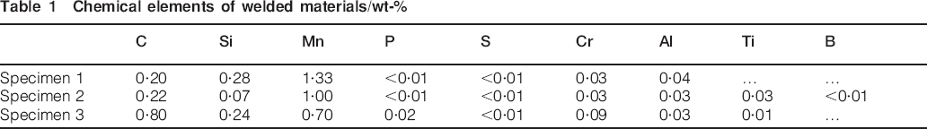
The experimental observations in this study are based on several welding tests, which have been carried out on endless rolling line. Three different steel grades were welded with comparable welding parameters so that the upset distance was kept at 27–30 mm in each weld with 12–15 s flashing time. The used flashing pattern was linear, and an upsetting current was not used. The temperature of the welded billets was 1173 K, and the cross-sectional area of the square joint was ∼13,225 mm2. After welding, the burr was removed, and the welds passed two sets of rolls since the cutoff of the specimens was simplest after the first two rollers. The finished specimens were round, ∼90 mm in diameter and cooled freely from 1173 K to room temperature. The specimens were then cut for bend and tensile test bars and sections for macro- and microstructure examination. The major chemical elements of the steel grades are presented in Table 1.
Chemical elements of welded materials/wt-%
Results
Observations of flat spot appearance
A typical flat spot in a fracture surface of the hot welded flash weld is presented in Fig. 1, where the bend test bar of specimen 1 has fractured at the weld seam during the bending test. These flat fractures developed only in bending tests. It was noticed that the tensile strength tests were not as effective as bending to reveal these kinds of defects. The fracture surface of a flat spot appears as a dark, smooth and brittle zone of modified composition in an otherwise ductile fracture surface. With a scanning electron microscope (SEM), the structure of the flat spot was studied more carefully. The difference in structures of the ductile base metal and the brittle flat spot can be seen in Fig. 2, which is taken from right side of the flat spot of Fig. 1. The area of flat spot can be seen as a darker dimpled zone where segregated solid particles are present. The dimpleness of the flat spot surface makes it darker on the fracture surface, as seen in Fig. 1.
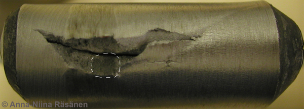
Flat spot on weld fracture surface of specimen 1: width of bend test bar is 75 mm
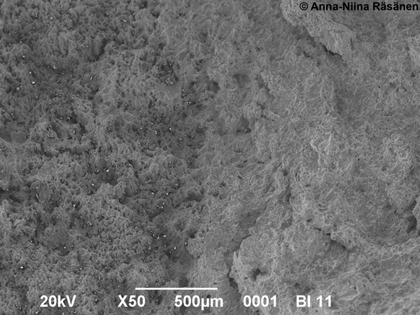
Image (SEM) of flat spot (left) and pure, ductile fracture surface (right) in specimen 1
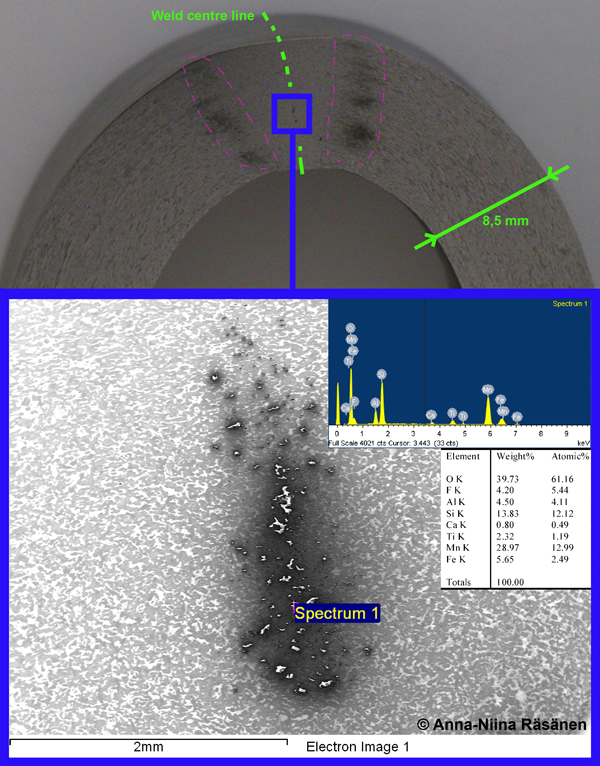
The flat spot consists of little, solid slag particles, which can be better seen in Fig. 3. These slags contain notable high amounts of oxygen, manganese, silicon, aluminium, fluorine and titanium respectively. The larger slags charged more than the smaller ones and thus showed lighter in the SEM images. Larger slags consisted also of larger amounts of preceding chemical elements than the smaller ones. The fluorine content of slags is extraordinary, since fluorine is not an alloying element of steel or used in steel production, at least not before casting.
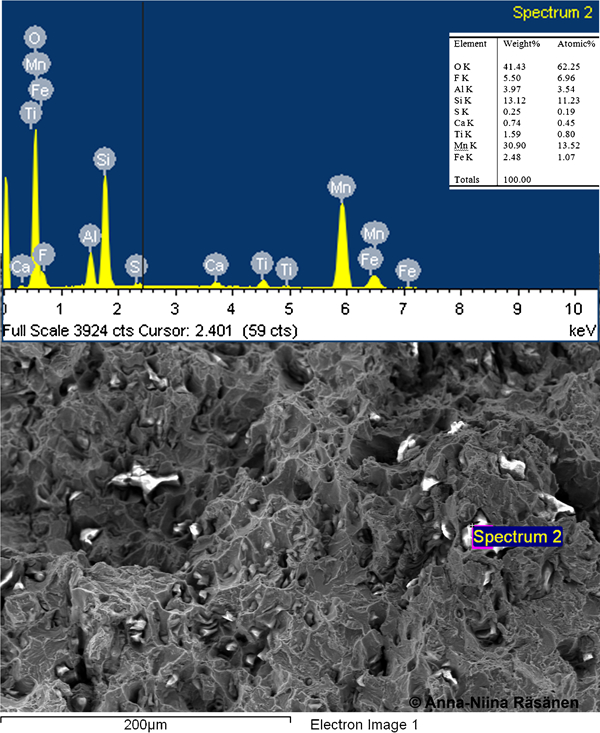
Image (SEM) and EDS analysis of oxidised slags on flat spot fracture surface in flat spot in specimen 1 (Fig. 1)
As Savage has presented, the flat spot is often surrounded with zones of segregated carbon. This can be better seen in Fig. 4, where oxide slags, which would generate a flat spot if ruptured, are represented on a cross-section of the bend test bar.
Oxide slags in weld joint on macrosection of bend test bar in specimen 1: ellipsoid shaped zone of segregated carbon is visible on macrosection and marked with pink dash lines
Essence of oxide inclusions
Oxide inclusions in the hot welded flash welds are typically located in the middle of the weld and in the edges of the weld seam. The found oxide inclusions appear usually in different sizes of groups and seem to be more or less scattered, likely by the influence of upsetting. The typical scattered appearance of the oxide slag group can be seen in Figure 4 Figs. 4 and 5. Often, there is also a visible ellipsoid shaped zone with different etchabilities and higher hardness around the oxide slags, the same that appear often around the flat spot. The ellipsoid zone can be seen in the macrosection of Fig. 4, where the ellipsoid zone is marked with pink dash lines. The harder ellipsoid zone that seems to be formed by segregating carbon has higher strength than oxide slags on the grounds of bend, tensile tests and hardness measurements. It should be mentioned that the ellipsoidic zone of carbon segregation is detected also in a few samples of specimens 1 and 2, where weld defects have not been found. On the grounds of bending test, the severeness of oxide inclusions seems to be related to their frequency of occurrence in certain areas. Small individual oxides did not fracture beyond a few millimetre long fractures during 180° bending test, but in areas containing groups of oxide slags, as in flat spot in Figure 1 Figs. 1 and 2, severe fractures appeared already with low bending angles. The ellipsoidic zone of the segregated carbon often yielded rather than fractured in the bend tests if no oxides were present on the ellipsoidic region. None of the tensile strength tested samples of specimens 1–3 fractured from the oxide defect areas even though visible carbon segregation areas and possible oxide inclusions were seen on the deformed surfaces of the test samples of specimens 1 and 2. The typical hardness values of the ellipsoidic zone around oxides compared to ‘pure’ weld seam in specimen 1 are represented in Fig. 6; the hardness of the ellipsoidic zone is always a little higher than that of the base material. Similar hardness values of segregated carbon zones have been measured on sections of specimen 2.
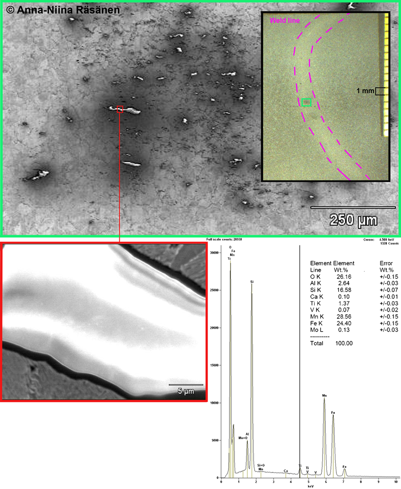
Macro- and SEM images of oxide slags in weld centreline in etched section of specimen 3: slags that are directed perpendicular to longitudinal direction of weld seem to contain high amounts of oxidised Mn, Fe and Si compounds as presented in EDS analysis of marked slag
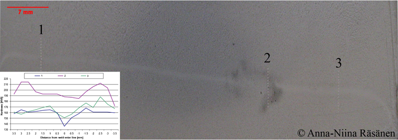
Hardness scans over segregated carbon zone and ‘pure’ weld seam in specimen 1
The groups of oxidised slags have been found in all the studied specimens when the welding procedure has been insufficient; however, the presence of the ellipsoid zone around the slags does not appear in all steel grades. It has not been noticed in samples of specimen 3, which the carbon content is notably higher than that of the others. The composition of the oxides is basically the same with those of flat spots, i.e. high amounts of manganese, silicon, aluminium and fluorine respectively. In addition to the former, also a few weight per cents of titanium was found from all oxide slags in specimen 1, even though titanium was not an alloying element of steel nor was it present in the cast analysis. The analyses of oxide slags can be seen in Figure 4 Figs. 4 and 5.
Discussion
The found oxides in all three steel grades are identical, and thus, it seems that the composition of the steel does not have a great effect on the oxide formation or their quality. The oxidised elements are, irrespective of their amounts in steel composition, manganese, silicon, aluminium and titanium. For example, amounts of titanium have been found in all oxide slags in all specimens even though, e.g. specimen 1 does not contain any titanium on the basis of cast analysis. The chemical composition of oxides was confirmed with tens of randomly taken analyses of oxide groups and single inclusions in studied specimens. The chemical analyses of oxides of each specimen follow the percentage values presented in Figure 3 Figure 4 Figs. 3–5. Fluorine appeared in the oxidised slags of all the studied specimens, but not in each analysed slag.
The severeness of oxide inclusions for weld properties depends on their sizes and locations with respect to the load or working rate of the weld. It was noticed that especially the tensile strengths of defect containing specimens were good since fractures developed in every case to the base material. It should still be considered that in upgraded products, e.g. in rolled wire, the found sizes of slags could be detrimental also in the quality of tensile strengths even though their presence is not always as serious as in the welded condition. Oxide inclusions may form a flat spot fracture if there are enough suitable sizes of oxide slags clustered in certain areas, as it is in the sample of specimen 2 presented in Figure 1 Figs. 1 and 2. The rupture of oxides into the flat spot may happen, e.g. during mechanical testing. It is presented by other authors that flat spots could be eliminated by increasing the upset value, but as the flat spot is formed of oxide slags, it could be suspected that the increase in upset would splinter the oxides around the interface, as it is mentioned to happen in the case of oxide inclusions. The authors suspect that the more important factor instead of upsetting distance in the removal of oxides is the fluency of the interface during upset.
The ellipsoid shaped zone, which seems to be segregated carbon, is believed to take the form of initial crater rims formed by arc strike during flashing. A few individual crater rims are believed to remain in the welds of specimens 1 and 2 since segregated carbon areas were observed; furthermore, oxides can easily be trapped in these areas, as was found in some cases. The segregation does not take place in the welding of all studied steel grades, even though the welding parameters have been the same. The ellipsoid zone of carbon segregation has not been noticed in high carbon steels based on micro- and macrostructural studies of all the test samples of specimen 3. Therefore, it should also be studied if there could be some differences in flashing voltages and arc strikes between different steel grades.
High flashing voltage is always followed by craters, and thus, the risk of flat spots, penetrators and also remaining oxide inclusions increases even if the upset force is increased. In the authors’ experiments, penetrators were not noticed since it seems that the flashing voltage was kept low enough so that massive arc craters were not formed. The difference between formation probability of flat spots and oxide inclusions is basically the amount of localised oxides left in the weld interface. This has also a connection to the evenness of surfaces after flashing. With the use of upsetting current, the amount of contaminants in the interface may be decreased since the resistance heat keeps the material more fluent during upset. In the case of large joint cross-sections, like in the case of the specimens in this study, the use of upset current and welding quality comes even more important because the melt and impurities have a longer way to extrude out from the central parts of the joint. The elimination of oxide containing defects still needs further studies.
Conclusions
By means of experimental studies, the following conclusions can be established.
The chemical compositions of flat spots and oxide inclusions are basically the same since they both seem to have formed from oxidised slag trapped in the weld interface.
In the case of flat spots and penetrators, the oxidised slag is trapped in the craters, which are formed from the arc strike after contact with too excessive flashing voltage. This theory is supported by the literature but still needs further studies.
Oxides may remain in the weld interface even with lower flashing voltages if the upset conditions are not fluent enough.
Based on experimental observations, the differences between flat spots and oxide inclusions are their appearance. Flat spots are fracture surfaces, which appear as dark dimpled zones of oxidised slags and are hazardous defects. Oxide inclusions are slags and can also appear in non-fractured surfaces, and thus, they are not always so serious defects in flash welds. This is because their bending does not always lead to fractures, which are more like dependent on the frequency of occurrence of these inclusions.
In both cases, the oxygen contamination to the melt has happened during welding action, but the defect size and type are still quite dependent on the welding parameters and thus the surface quality of the interfaces and temperature. It seems that the protecting atmosphere alone in flash welding is not sufficient enough to eliminate all the oxygen contaminations in the melt; this increases the importance of upsetting and upsetting current to get rid of all the unwanted contaminants.
Carbon segregation around flat spots or oxide inclusions is significant in low carbon steels and seems to interrelate rather to the initial crater rims than the actual defect type inside it.
Footnotes
Acknowledgements
The authors wish to acknowledge the Finnish Funding Agency for Technology and Innovation for partial funding of this research work and the staff of Ovako Wire Oy Ab, Taalintehdas, rolling mill for providing facilities and support for experimental studies. Special acknowledges are given for LicSc A. Järvinen and MSc Techn. J. Salo for theoretical support and guidance during this research work.