
Abstract
Polyetheretherketone (PEEK) is a semicrystalline thermoplastic with excellent mechanical and chemical resistance properties that are retained to high temperatures. For these reasons, it is classified as a high performance thermoplastic. The first reinforced PEEK product was an impregnated continuous carbon fibre pre-preg tape called APC-2, but since then there have been many others. Most of the applications using PEEK involve joining it to itself or to another material; for instance, in the automotive or aerospace industries, lightweight structures need to be joined to metallic surfaces. However, the challenging processability of PEEK due to its high melting point (343°C) and high melt viscosity remains a limitation for its extensive use. This characteristic makes the processing of it time and energy consuming. Even so, interest in this thermoplastic is currently growing, driven by the constant search for lightweight and recyclable materials. Solutions to overcome these process limitations are investigated in this paper through joining of PEEK to similar and dissimilar materials. The common concept behind these solutions is the use of an accelerating agent at the joining interface aiming to produce good welds faster. The main solution investigated is the use of a plasticiser, which is usually used to reduce the viscosity of PEEK and increase its chains mobility.
Introduction
Background
There is currently considerable interest in the manufacture of components and products from composite materials including thermoplastic composites. These materials have excellent strength and stiffness to weight ratios and can be recycled by virtue of their melt processability. The increased use of carbon composites, particularly in aerospace and offshore wind industries, is driving significant funding directed at rapid manufacture research programmes. Thermoplastic composites, in particular carbon/polyetheretherketone (PEEK), are seen as key materials potentially meeting demands for higher levels of automation and high performance materials.1
A popular method to manufacture thermoplastic composite components and parts is automated tape laying, known as ATL. One of the most well known pre-pregs used for this laying technique is a PEEK impregnated unidirectional carbon fibre tape called APC-2.2 Its processing is currently being studied, enhanced and used widely.
Unreinforced PEEK components are currently gaining interest across various industries as well. For instance, PEEK films are currently used for various applications from speaker diaphragms to burn-through barrier laminates for aircraft insulation system.3
Dissimilar material joining of thermoplastic onto metal is an underdeveloped field and rarely applied in industry currently. Some progress has, however, been made in terms of bonding such as the polymer coated material technique, with a focus on PEEK.
The quest for lighter yet stiff structural materials in the automotive and aerospace industries, associated with the sustainably driven need for recyclable or reusable materials is causing thermoplastic composite solutions to gain in popularity. This recent increasing interest requires methods for joining these materials to metallic structures.
Although PEEK appears to be of great potential, its current weakness lies in its challenging processability caused by its high melting point and high melt viscosity.
Approach
The main challenges typically encountered whilst joining PEEK are caused by its high melting point and high melt viscosity. To address this problem, the use of accelerating agents, with a focus on a plasticiser called diphenylsulphone, which can decrease the viscosity of PEEK, was investigated and is presented in this paper.4, 5
Scope
In order to conduct a complete investigation of the effect of the introduction of a plasticiser at the joining interface, it was decided to carry out the present study across three joining techniques, using different materials:
hot bar welding of APC-2/AS4
through transmission laser welding of PEEK
dissimilar joining of short carbon fibre/PEEK to titanium.
Objective
This paper is aiming at investigating the potential of diphenylsulphone as an accelerating agent for fabricating PEEK and PEEK to titanium joints.
Experimental
Accelerating agent
Accelerating agents’ requirements were investigated with a view to increase the welding speed of PEEK, and hence achieving high productivity. Accelerating agents were chosen on the basis of their plasticising effect on PEEK. A plasticiser can be defined in different ways, but a generic property for such a compound is that its chemical structure makes it compatible or miscible with the polymer it plasticises. There is a potential relationship between compatibility and similarity in the chemical structure of the plasticiser and the polymer unit. Diphenylsulphone has been suggested as a potential plasticiser for PEEK6 (Fig. 1).
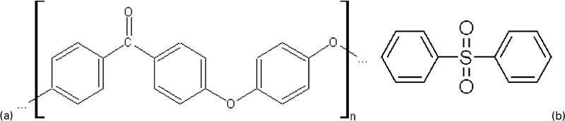
Chemical formulae for a polyetheretherketone and b diphenylsulphone
Dissimilar joining
There is a need for the melted polymer to effectively wet the metal's surface. Preliminary tests were carried out in order to investigate an appropriate pre-treatment leading to a good weld. Anodising is a common preparation for titanium; it however did not allow the creation of strong welds on its own. When combined with a coating of the anodised titanium (Fig. 2), strong welds were created. The coating was formulated from diphenylsulphone and low molecular weight PEEK. The procedure for preparing the titanium is described below:
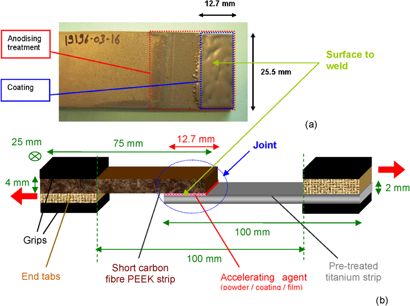
a coated titanium strip after full pre-treatment and b single lap shear specimen dimensions
first step: anodising
The titanium strips (100 ×25·5 mm) were anodised according to BS EN 13887:2003/7·2·11·2; the third method was applied.
second step: coating
The anodised titanium strips were locally heated up to 400°C. An area of 25·5×12·7 mm at one end of the titanium plates was coated with the formulated coating powder (Fig. 2).
In order to join the selected PEEK strips (4 mm thick; 75×25·5 mm; short carbon fibre reinforced PEEK) to the titanium, a hot bar (Fig. 3) using a flat heated pad was used, and its temperature was varied in order to achieve interfacial temperatures ranging from 350 to 380°C. The heated pad was pressed against the titanium which acted as a clamp onto the PEEK strip, causing the PEEK to melt locally. The hot bar was withdrawn once a continuous extrusion line of a couple of millimetres was observed around the joint line, which was an indication of the even melting of the PEEK surface, and therefore of the coating too, at the joint interface.
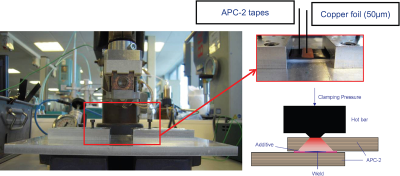
Hot bar welding assembly and hot bar welding schematic
Shear tests were carried out using a Hounsfield 50 kN Instron tester. Settings were: speed, 1·3 mm min−1 and gap (interjaws), ∼112 mm.
Similar joining
Hot bar welding
The hot bar equipment used (Fig. 3) consisted of an assembly composed of a heating cartridge embedded in a copper bar, or heating block, attached to a heating pad, which transferred the heat and pressure to the workpieces to weld. The motion of the whole assembly was driven by pneumatics accurately controlled with a precision pressure gauge and a precision pressure valve; the maximum cylinder pressure was 4 bar. The temperature was controlled by a Watlow controller (series 965). In the case of similar joining, the alignment of the test specimens was ensured by a clamping system shown in Fig. 3.
APC-2/AS4 was selected for the hot bar study for its potential use in ATL and because its 60% continuous carbon fibre content allow it to maintain its dimensional structure during processing.
In the absence of a standard for the manufacture of specimens using thermoplastic films, the initial design of the specimen was based on standard single lap shear specimens.7 Therefore, 25 mm wide specimens with a 10 mm wide weld were initially produced. They, however, underwent structural distortion during testing as the joint area was too large. The width of the weld was hence reduced to 3 mm and the width of the specimen was reduced to 10 mm (Fig. 4), and the distortion of the specimens was greatly reduced, allowing the failure to be generated in the joint and not in the parent material.
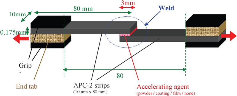
Single lap shear specimen dimensions
The plasticising additive was either applied in its original powder form using a brush or was melted and coated onto the APC-2/AS4 via dip-coating. APC-2/AS4 comprises only 40% of polymer (the rest is carbon fibres), leading to a polymer poor welding interface; for this reason, the use of amorphous PEEK films (APTIV 2000-006G and 2000-012G) as an additive at the interface was also investigated: the films were cut to size and placed at the interface before welding.
Shear tests were carried out using a Hounsfield 50 kN Instron tester. Settings were: speed, 10 mm min−1; gap (interjaws), 80 mm.
Laser welding
Through transmission laser welding of plastics uses near infrared laser radiation to weld plastic workpieces (films, sheets and complex components). It requires both a laser transmissive and laser absorbing workpiece, or an absorbent layer at the interface.8
A diode laser from Laserline (LDL160-300) was used, which provided an output of up to 150 W at a wavelength of 940 nm. A sliding clamping ring of 35 mm external diameter and 12 mm internal diameter applied a load of 528 N on a 5 mm thick transparent acrylic sheet placed on top of the PEEK films to weld. The purpose of the acrylic sheet was to distribute the load in order to ensure intimate contact under the laser beam and therefore effective welding.
Different combinations of PEEK films were initially investigated in order to identify which ones allowed the production of a weld (Fig. 5). A continuous laser beam was used to weld the above combinations, the spot dimensions were 3×8 mm and the power and speed were varied until achievement of an acceptable weld. This speed was in the range of 3 to 5 m min−1 and the power was in the range of 30 to 150 W. For each combination, suitable speed and power were identified.
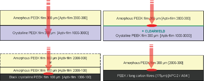
Different combinations of PEEK films investigated for laser welding
Amorphous PEEK (APTIV films in the present study) was used as an upper workpiece as it is transmissive at the radiation used. When the lower workpiece was an unfilled crystalline PEEK film (Fig. 5, top left), the heat absorbed at the interface was insufficient to create a weld. Once Clearweld IR radiation absorber was applied at the interface (Fig. 5, top right), good welds were achieved for a laser speed of 4 m min−1 and a power of 100 W. However, their quality appeared to be greatly dependent on the amount of absorber deposited. The most repeatable combination for producing strong welds was when a black lower workpiece was used (Fig. 5, bottom). For the combination using 100 μm thick black PEEK film, good welds were achieved for a laser speed of 4·5 m min−1 and a power of 30 W. For the combination using APC-2/AS4, good welds were achieved for a laser speed of 3 m mi−1 and a power of 100 W.
The strength of the initial welded joints was determined using both a shear test and a peel test. For both tests, the specimen dimensions were 20 mm wide and 100 mm long. For most of the PEEK film combinations successfully welded, the weld area (10×5 mm) was too large and resulted in failure or yielding in the parent material.
This resulted in a binary treatment of the measurements. When the failure was generated in the weld, the weld was ‘poor’, and when it occurred in the parent material, the weld was ‘good’. However, this technique did not distinguish between good welds, hence greatly limiting the quality of the comparisons and the relevance of the results.
As a consequence, it was decided to reduce the dimensions of the weld until the failure of welded specimen was always generated in the weld. Also the stronger films were selected: 300 μm amorphous PEEK film as the top film and APC-2/AS4 as the lower film. The use of a mask, in place of an acrylic sheet, allowed a reduction of the weld size and increased the repeatability of the weld shape. The mask was produced out of non-treated mild steel (2 mm sheet) containing a row of 1 mm diameter holes spaced either 5 or 10 mm apart.
The 300 μm thick amorphous PEEK film (Aptiv film 2000-300) was tested alone in tension for the test specimen widths of 15 and 20 mm. The resulting average yield loads were 300 and 370 N respectively.
The 1 mm diameter hole mask was used to manufacture single lap shear specimens with three spot welds spaced 5 mm apart (Fig. 6a) and two spot welds spaced 10 mm apart (Fig. 6b). These specimens were successfully shear tested without failure in the film since the shear strength of these specimens was lower than the yield load of the APTIV 2000-300 films.
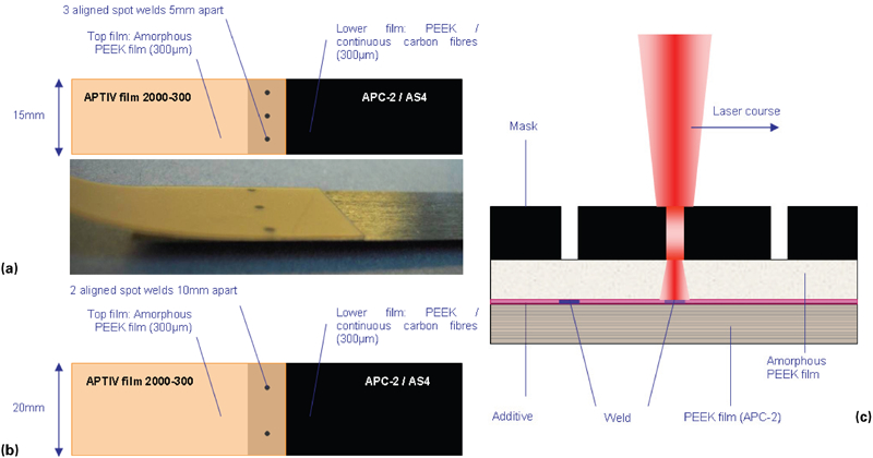
Schematic of welded specimen prepared using 1 mm diameter hole mask
Series of experiments were therefore performed using the 1 mm diameter hole mask at laser course speeds between 3 and 4 mm min−1. Some welded interfaces contained no additive in order to produce reference specimens, and some contained diphenylsulphone deposited by spray at a concentration of 6 wt-% in a 1,3-dioxolane solution.
Shear tests were carried out using a Hounsfield 50 kN Instron tester. Settings were: speed, 10 mm min−1; gap (interjaws), 50 mm. Two types of welded specimens were investigated, as illustrated in Fig. 6.
Results
Dissimilar joining
Most of the specimens failed in the parent material, in the vicinity of the weld, at a load greater than 5000 N, demonstrating the high strength of the welds created using the pre-treatment described in the section on ‘Dissimilar joining’. For the same reason, no weld strength measurement was possible (Fig. 7).
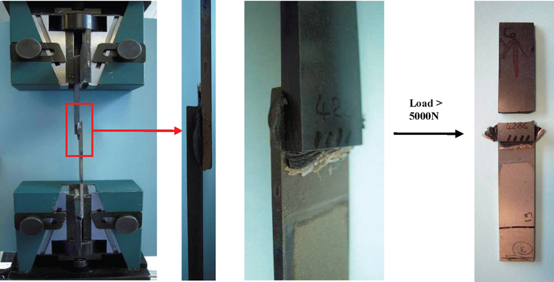
Typical single lap shear test for dissimilar joint and most common failure obtained
In the absence of an anodising pre-treatment or coating, the specimens showed poor joint strength.
Similar joining
Hot bar welding
Hot bar welded specimens were produced and tested (Fig. 8): some welded interfaces contained no additive to produce reference specimens, some contained diphenylsulphone or amorphous PEEK films.
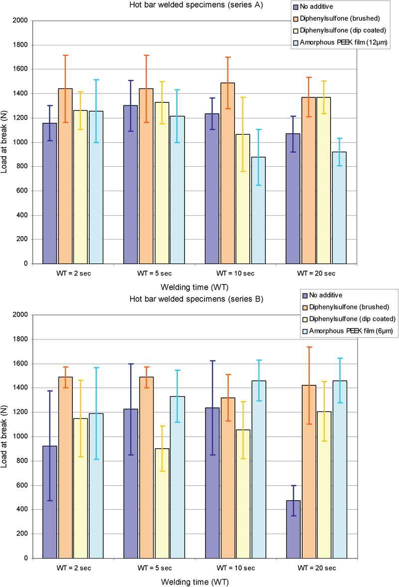
Loads at break of welds using various additives for different welding times; (series A) hot bar was set at 475°C and the maximum interfacial temperature was 405°C; (series B) hot bar was set at 450°C and the maximum interfacial temperature was 385°C; the interfacial temperature underwent cooling rate of (series B) 90 or (series A) 150°C min−1 during the welding process. Histograms show the average value of the group of specimens tested (six per group); the bars show the standard deviation
The interfacial temperature and its evolution during the welding process were measured during an initial calibration study. The specimens were produced using a cylinder pressure of 2·5 bar.
The most significant improvement observed among the different formulations tested at the interface appeared to be when diphenylsulphone powder was introduced at the interface with a brush, this effect being more particularly noticeable at lower temperature.
Through transmission laser welding
Laser welded specimens were produced and tested (Fig. 9): some welded interfaces contained no additive to create reference specimens, some contained diphenylsulphone.
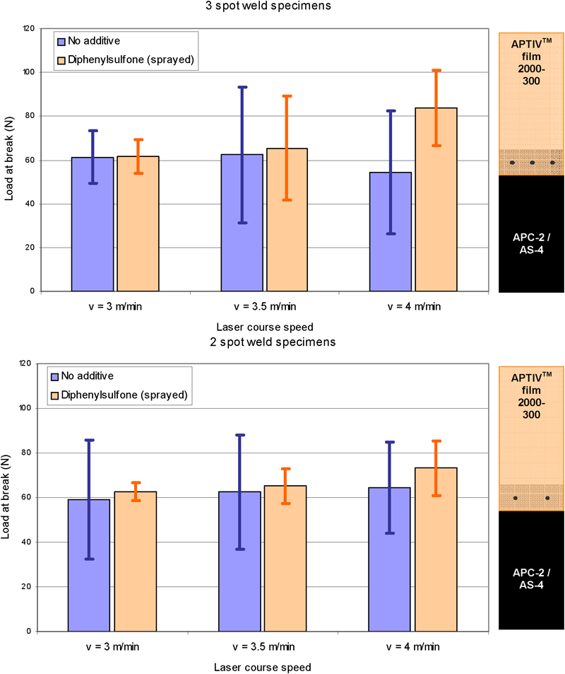
Load at break measurements for different batches of specimens welded with the 1 mm diameter hole mask: (top) three spot welds specimens (15 mm wide); (bottom) two spot welds specimens (20 mm wide). Histograms show the average value of the batches tested (six specimens per batch) and the bars show the standard deviation
These results suggest that the use of diphenylsulphone led either to an increase in the strength of the weld or to a reduction of the number of poor welds, this effect being more particularly noticeable at high speed.
Conclusions
Dissimilar joining
The use of a coating made of diphenylsulphone and low melt viscosity PEEK led to excellent welds. It was demonstrated that in the absence of such pre-treatment, poor welds were achieved. It is believed that the difference of stiffness of the joined materials (titanium and short carbon fibre reinforced PEEK) induced a bending moment in the vicinity of the weld, leading, in most cases, to the failure of the composite parent material, therefore preventing the effective measurement of the weld strength.
Most of the failures occurred in the parent material at a load greater that 5000 N, suggesting that the weld strengths were, on average, superior to 5000 N.
Similar joining
The use of diphenylsulphone at the joint interface has a positive effect on the shear strength of welds in PEEK. This effect was shown to be more significant at an interfacial temperature of 385°C than at 405°C in the case of the hot bar welding and at a laser speed of 4 m min−1 rather than 3 m min−1 in the case of the through transmission laser welding. 400°C is the conventionally recommended processing temperature for PEEK9 and yet its melting point is 343°C. It is highly probable that the reason for this recommendation is to reduce the melt viscosity and as a consequence to create a weld faster whilst using less pressure.
It seems reasonable to conclude that the accelerating property of diphenylsulphone, when used as an additive for the welding of PEEK, is more significant when less energy than usual (lower temperature, higher speed) is used. In this case, diphenylsulphone leads either to increased weld strengths or to a reduction of the number of poor welds, as opposed to joints without additive.
The use of diphenylsulphone is therefore a possible alternative to the use of ‘high’ processing (e.g. ATL, stamping, moulding) temperature and pressure for the welding of PEEK and particularly of APC-2/AS4.
The use of a thin amorphous PEEK film when APC-2/AS4 was welded to itself led to stronger weld than in the absence of additive. This trend was observed for a 6 μm thick film, and at an interfacial temperature of 385°C.
Future work
In the case of dissimilar joining, there is a need for enhancing single lap shear test specimens with parent materials able to withstand tensile loading, therefore generating failure in the weld allowing the effective measurement of the weld strength. Future work will, therefore, use structural composite (unidirectional or woven carbon fibres) instead of the short carbon fibre reinforced PEEK used so far. Once failure in the weld is achieved, the comparison of different coating formulations will be possible.
In the case of similar joining, future work will concentrate on the ‘low-temperature’ welding of PEEK, using diphenylsulphone as an accelerating agent. The effect of the addition of an interfacial amorphous PEEK film will also need to be investigated.