
Abstract
A new technique of filling friction stir welding (FFSW) relying on a semiconsumable joining tool has been developed to repair the keyhole left at the end of friction stir welding (FSW) seam. The conventional non-consumable tool of FSW was transformed, and a semiconsumable joining tool consisting of alloy steel shoulder and aluminium alloy joining bit was designed to create a solid state joint. Using the combined plastic deformation and flow of the consumable joining bit and the wall of the keyhole, the FFSW process is able to repair the keyhole with both metallurgical and mechanical bonding characteristics, and the FSW seam can be achieved without keyhole or other defects. The relative tensile strength and elongation of the FFSW joint are 84·3 and 98·9% of the base weld without defects respectively.
Introduction
Friction stir welding (FSW) is a relatively new solid state joining process in which a rotating non-consumable tool with a shoulder and a protruding pin moves along the butting surfaces of two rigidly clamped plates placed on a back anvil. 1 1,2 The joining technique is energy efficient, environment friendly and versatile. In particular, it can be used to join high strength aerospace aluminium alloys and other metallic alloys that are hard to weld by conventional fusion welding. The FSW is considered to be the most significant development in metal joining in the past two decades.3 However, in the fast development and application of the FSW process, it has been known that welding defects may be formed when improper welding parameters or technological conditions are used,4– 6 and such defects as groove, cavity and kissing bond have significant influences on the mechanical properties of the joints. 7 7,8 Furthermore, the keyhole inevitably remains at the end of the weld, from which the non-consumable pin is withdrawn after FSW or friction stir spot welding (FSSW) process. Both lap shear and cross-tension strengths are limited due to the relatively small bonding widths.9 The keyhole acts as ‘the weakest link effect’ to the mechanical properties and other performances. In addition, a new solid state spot joining process called friction bit joining (FBJ), which relies on the use of a consumable joining bit, has been developed.9– 11 The bonding widths of FSSW joints have been increased, and ‘the weakest link effect’ of the keyhole has been solved. The lap shear strength of the FBJ welds was better than that of self-piercing rivets, and the FBJ was capable of joining soft and very hard material combinations, like AA 5754 and DP 980 steel.11 This concept relies on a cutting step, where the bit cuts through the top layer of the material, followed by a joining step, where the bit and surrounding sheet materials are heated by friction and where the bit is consumed as filler material that joins the sheets together. At the end of the joining process, the spindle of the welding machine was stopped and then restarted to separate the joining bit from the weld.9– 11
In view of keyhole or other defects, the re-FSW was utilised to remove such defects as groove, cavity and kissing bond.12 Unfortunately, the keyhole would emerge again when these defects were repaired. In a way, the double acting FSW tools,13 or named retractable 14 14,15 or autoadjusting16 FSW tool, consisting of outer shoulder and inner pin, have been developed in order to refill the remained keyhole.13 A current solution to the retraction problem that the National Aeronautics and Space Administration and many other manufacturers have adopted is an exceedingly complex, hydraulically actuated retractable pin tool apparatus.16 An autoadjusting pin tool welding head comprises a motor connected to a controller instrument package, and an arbour that forms an interior cylinder encircled by a stationary slip ring, so that a piston within the arbour may be moved axially.16 The tool is plunged into workpieces similar to conventional FSW and FSSW process, while the inner probe is retracted into the outer shoulder after joining, and then the flat face of the tool is again plunged in order to refill the keyhole that was previously occupied by the tool pin.15 Therefore, the weld joint can be terminated without leaving a keyhole at the weld terminus. Since the material is made to flow into the keyhole formed in the workpiece by the pin, during the upward pulling of the pin, the keyhole is filled at the final stage of the welding process. However, a wide and shallow keyhole depression still remains at the weld centreline due to the inadequate material to fill the narrow and deep keyhole. Thus, ‘the weakest link effect’ induced by the keyhole has not been solved completely.
In the present work, a new technique of filling friction stir welding (FFSW) was developed to refill the keyhole and repair the defects of FSW weld based on the basic principles of the solid phase joining technology using a conventional FSW machine instead of exceedingly complex, expensive FSW machine with retractable pin tool apparatus.
Experimental
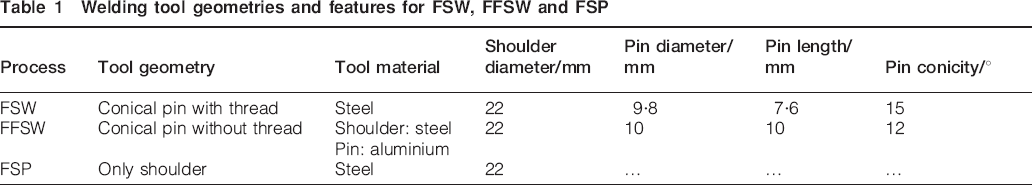
The material used is Al–Cu–Mg aluminium alloy sheet with thickness of 7·8 mm. The initial heat treatment is T6 (solutionised at 535°C for 4 h, water quenched and aged at 185°C for 24 h). The FFSW processing involves joining by friction, stirring and cutting, and the FFSW processing is finished using an FSW machine (FSW-3LM-003). In addition, friction stir processing (FSP) smoothed and reprocessed the FFSW joint with a non-consumable tool consisting of only a steel shoulder without protruding pin. Three tools are used to conduct FSW, FFSW and FSP respectively. The geometries and features of the tools are listed in Table 1. In particular, it should be stressed that the inherent pattern of FSW was transformed during the FFSW process, and the tool was composed of consumable joining bit made of the welded material and non-consumable shoulder made of the alloy steel, as shown in Fig. 1. Unlike the conventional FSW tool, the tool used in the FFSW process has three primary functions, i.e. localised heating, material flow and filler material.
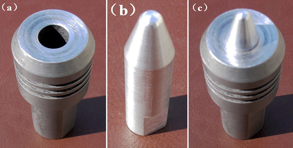
Photographs of FFSW tool
Welding tool geometries and features for FSW, FFSW and FSP
The parameters of FSW, FFSW and FSP are summarised in Table 2. These welding parameters were determined based on preparatory experiments, in which several welding parameters were tried including the design of the joining bits, the speeds and the feedrates. The FFSW process was carried out in three main steps: a friction step, a stirring step and a joining step. First, the concept relies on a friction procedure, where the bit gets in touch with the wall of the keyhole, rubs against the inner surface of the keyhole and self-cleans the bonding surfaces. Second, followed by a stirring step, where the aluminium alloy bit is plunged into the keyhole, the alloy steel shoulder contacts with the upper surface of workpiece, causing frictional heating to occur at the interface between the bit and the keyhole, and the materials of keyhole and bit are softened and stirred. At last, the joining operation was followed, the bit and the surrounding keyhole materials are heated by friction and the bit is cut and becomes filler material that joins the bit and the keyhole together. Severe plastic deformation and flow of plasticised metal occurs.
Welding technological parameters for FSW, FFSW and FSP
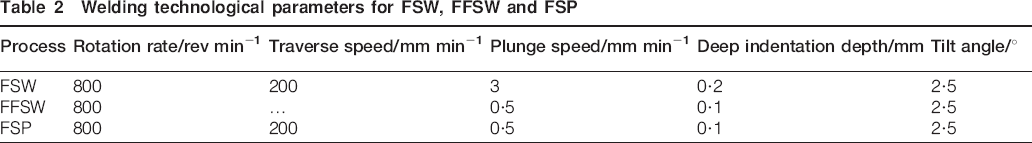
Photographs of the joint and the corresponding tool with different processes are shown in Fig. 2. During the FFSW process, the consumable aluminium alloy joining bit of the combined tool is plunged into the keyhole left at the end of the FSW joint. The heat generated by friction at the shoulder and the joining bit surface softens the material of keyhole wall and bit. In addition then, severe plastic deformation and flow of this plasticised metal occurs. The joining involves the filler metal of the aluminium joining bit, and the shoulder provides a forging force. It is clear that the keyhole left by the FSW was successfully filled by the transformed joining bit. In the following FSP, a non-consumable tool consisting of a shoulder without protruding pin provides mechanical mixing and plastic deformation. Meanwhile, the flash around the filled keyhole was abraded and stirred.
Photographs of joint and corresponding tool with different processes
Results and discussion
A macroscopic overview of the cross-section of the FFSW joint is presented in Fig. 3a. Macroscopic observation confirms that a defect free joint is successfully produced by the FFSW. The joining bit remains in the joint. Figure 3b shows the Vickers hardness profile along the line below the top surface 2 mm across the FFSW joint. The hardness is higher than that of the base metal due to the combined functions of FFSW and FSP. Figure 4a–e presents the details of the bonding interface between the joining bit and the keyhole at five different locations (see labels in Fig. 4). Since the interface region is located beside the joining bit, it would experience both frictional heating and several plastic deformations during the joining step of FFSW. Based on microstructural characterisation, five distinct zones, i.e. filled zone (FZ), quasi-nugget zone (QNZ), thermomechanically affected zone (TMAZ), heat affected zone (HAZ) and nugget zone (NZ), have been identified. During the FFSW process, the heating is accomplished by both friction between the tool and the keyhole and plastic deformation of the joining bit and the keyhole wall. The FZ has formed through the bonding and self-breaking of consumable joining bit due to the function of heating and shearing. The centre zone of the FZ does not experience plastic deformation. Near the FZ, the QNZ is defined, which undergoes extreme thermal Al–Cu–Mg mechanical deformation and material flow of the keyhole wall and the consumable joining bit. The TMAZ experiences both elevated temperature and plastic deformation. Heat is generated due to friction and plastic deformation at the tool/workpiece interface and due to plastic deformation in the TMAZ. The TMAZ could be observed over the entire width of the weld region. Beyond the TMAZ, there is an HAZ that experiences a thermal cycle but no plastic deformation. The nugget of FSP intersected with zones of FFSW is formed. The upper surface experiences extreme deformation and frictional heating by contact with the shoulder during FFSW and following FSP. The dynamic recrystallisation occurs in the NZ due to the severe thermomechanical processing, resulting in the homogenous fine equiaxed recrystallised grain structure. In addition, the FSP can modify successfully some properties such as yield strength, fatigue and superplasticity.17– 20 In the initial stage of tool plunge, the heating is primarily generated through friction between the joining bit and the keyhole wall. Meanwhile, some additional heating is generated through plastic deformation of the abutted material. The tool is plunged until the shoulder intimately contacts the workpiece. The friction between the shoulder and the workpiece results in the majority of heating. The localised heating softens the material around the joining bit and leads to movement of the softened material combining with rotation of the partly plastic deformed bit. With the combined functions of softening and torque, the joining bit is sheared at the corner of shoulder. Therefore, the keyhole is filled by the sheared joining bit. The plasticised material is forged by the intimate contact of the tool shoulder and then consolidated. It leaves a solid phase bond between the keyhole and the joining bit. As a result of this FFSW process, a joint is produced on ‘solid state’.
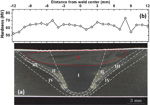
Optical macrograph and hardness profile of FFSW joint for 7·8 mm aluminium plate
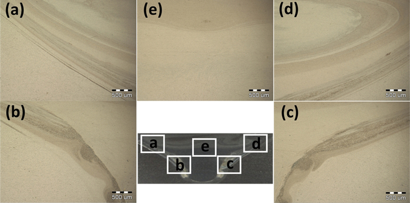
Bonding interface detail between joining bit and keyhole (refer to five different locations)
The welded joint is fundamentally defect free and displays excellent mechanical properties when compared to conventional fusion welds.21– 23 Tensile specimens were machined from the FZ in the direction normal to the weld. Tensile testing was carried out on specimens that were 15 mm wide and 150 mm long. In addition, tensile tests were performed at room temperature at a crosshead speed of 1 mm min−1. The tensile specimens in the transverse orientation cover six different microstructural zones, i.e. parent material, HAZ, TMAZ, QNZ, NZ and FZ. The observed ductility is an average strain over the gage length including various zones. Figure 5a shows the top and fracture surface views of the FFSW weld, and fracture occurs near the FZ. The original interface between the wall of the keyhole and the consumable aluminium alloy joining bit is a weak region due to the inadequate material plastic deformation and flow. Specimen extension was measured by means of a 50 mm extensometer attached to the reduced section. The elongation was determined by scribing marks with known separation within the reduced section before testing and measuring their separation after testing. Figure 5b shows the tensile test results of the base weld without keyhole and repairing joints by FSP without filler material, by tungsten inert gas (TIG) fusion welding and by FFSW. It can be seen that the joints by FSP and TIG have considerably poor mechanical properties. Particularly, the relative elongation is only 11·5 and 12·2% of the base weld respectively. However, when the FFSW process is utilised, the relative tensile strength is 84·3% of the base weld, and the relative elongation is 98·9% of the base weld. In addition, the relative tensile strength and elongation of the FSW specimen without defect is 64·4 and 94·2% of the base material respectively. The FFSW process increased the effective cross-sectional area of the nugget, resulting in higher tensile strength. Figure 6 displays the tensile fractured morphologies of the FFSW joint at the interface of the keyhole. The fractured surface is characterised by dimples and tearing edges, indicating that plastic deformation occurs during tensile test. Obviously, the FFSW process is able to repair the keyhole and overcome the ‘weakest link effect’.
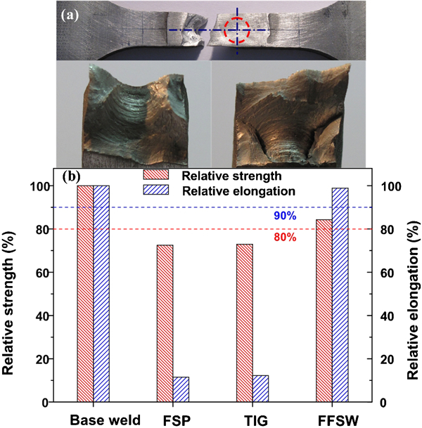
Tensile fractured view and performance
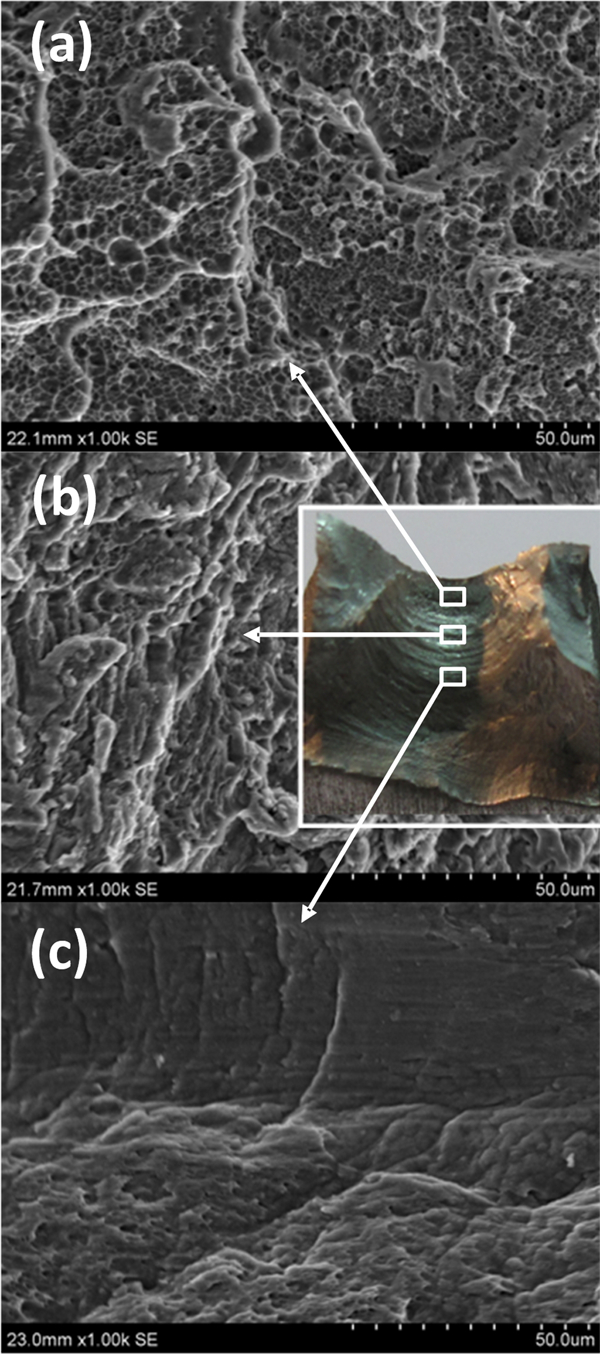
Tensile fractured appearance of FFSW joint at interface of keyhole
For FFSW, two parameters are very important: tool rotation rate and tool plunge speed along the axial line of the keyhole. The rotation tool results in stirring and mixing of the material around the rotating joining bit. Furthermore, the plunge depth of the joining bit into the keyhole is important for producing sound welds. The insertion depth is associated with the joining bit height and the keyhole depth. When the insertion depth is too small, the pin does not contact the bottom of keyhole adequately, and the shoulder does not contact firmly the original workpiece surface. Thus, rotating the shoulder cannot move the stirred material efficiently, producing welds with inner hole or surface groove. When the insertion depth is too large, the shoulder plunges into the workpiece, creating excessive flash.
As FSW, the FFSW advantages result from the fact that the process takes place in the solid phase below the melting point of the material to be joined. The benefits therefore include the ability to join materials that are difficult to be welded by conventional fusion welding, such as high strength aluminium alloy. However, several key problems and issues about the new technology of FFSW remain to study. First, the fundamental knowledge of the FFSW process and the evolution of the structure and properties need to be combined to build process control models with a goal to achieve, defect free, structurally sound and reliable welds. The framework has been provided to understand the material flow accounting for all of the observed phenomena and, in particular, the cyclic variation in the microstructure and process response variables.23– 26 Second, during the FFSW process, the heat produced by friction and stirring may be not sufficient to soften and plasticise the material around the rotating bit. It is difficult to produce a continuous defect free weld with abundant material plastic deformation and flow. Thus, preheating of the keyhole is important for the FFSW process, and preheating or additional external heating source can facilitate the material flow and increase the process window.
Conclusions
A new technique of FFSW using a semiconsumable tool consisting of alloy steel shoulder and aluminium alloy joining bit has been performed to repair the keyhole or defects that left during the FSW process. The tool of the FFSW serves three primary functions, i.e. heating of workpiece, movement of material and filling the keyhole to produce the joint. The microstructures of the FFSW joint were classified into five distinct zones, i.e. FZ, QNZ, NZ, TMAZ and HAZ. The FFSW process is able to repair the keyhole with quasi-equivalence mechanical performances, and an FSW seam without keyhole can be achieved. For the joint of FFSW, the relative tensile strength is 84·3%, and the relative elongation is 98·9% of the base weld without keyhole, higher than that of the FSP without filler material and TIG fusing weld. In conclusion, the ‘weakest link effect’ induced by the keyhole has been solved by the new solid phase joining technique. Furthermore, the integration of welding and in situ repairing has been realised using a conventional FSW machine.
Footnotes
Acknowledgements
This work was jointly supported by the National Natural Science Foundation of China (grant no. 50904020), the Science and Technology Innovation Research Project of Harbin for Young Scholar (project no. 2009RFQXG050) and the China Postdoctoral Science Foundation (grant no. 20090460883).