
Abstract
A fibre laser was used to join Ti–6Al–4V alloy to AZ31B Mg alloy with the same thickness of 2 mm, and a filler wire was used to avoid weld underfill resulting from Mg vaporisation. The acceptable joints were only obtained when the laser beam was offset from the edge of the weld seam at 0·2 mm to the AZ31B side of the joint. Cross-weld tensile testing found joint strengths of up to 200·3 MPa, which is 85·1% of the AZ31B tensile strength. All the joints were fractured at the Ti/fusion zone interfacial layer. When the laser offset increased from 0·2 to 0·3 mm or laser power reduced to 1·2 kW, the joining mode of the interfacial layer changed from a semimetallurgical joining with high strength to a mechanical joining with poor strength. Moreover, the fracture surface of acceptable joints was characterised by scraggly remaining weld metal, while that of poor joints was almost only characterised by smooth Ti surface.
Introduction
Recently, the joining of dissimilar metals has received more and more attractions for it can save cost by reducing the usage of expensive materials and get better performance by gathering the advantages of different metals in one part.1– 3 In fact, most of the different metals have been joined together, such as Al/Cu, 4 4,5 Al/steel,6, 7 Cu/steel,8 Ti/steel,9– 11 Ti/Al,12, 13 Mg/steel14– 17 and Al/Mg.18– 20 However, though the two light metals Ti and Mg have some unique properties, no attention has been addressed on joining them together. Mg alloys have low density, high specific strength along with good damping capacity,21 while Ti alloys have large specific weight, excellent corrosion resistance and high temperature performance.22 On the other hand, their applications are going rapidly in aeronautic, automotive and defence industries in recent years due to these unique properties. Consequently, the study of joining dissimilar Ti/Mg alloys will be interesting.
The challenge of joining Ti/Mg alloys comes from the great difference in melting points and the nearly zero intersolubility between Mg and Ti.23 The maximum solid solubility of Ti in (Mg) is 0·12 at-% and that of Mg in (Ti) is nil. The melting points of pure Mg and Ti are 922 and 1941 K respectively, which makes them very difficult to melt at the same time. Then, the appropriate welding process is important for getting a good Ti/Mg joint. Although diffusion brazing and friction stir welding have shown big advantages in joining dissimilar metals, high density beam welding (laser and electron) with precise power control has greater advantages in joining efficiency and flexibility. Nowadays, laser welding has been developed to join dissimilar Mg/Fe alloys,14– 17 which also have nearly zero intersolubility and great difference in melting point. In these studies, good joining strengths were obtained, the maximum of which reached 182 MPa. This indicates that joining dissimilar Ti/Mg alloys is feasible.
This article aims to investigate the fibre laser welding of 2 mm Ti–6Al–4V alloy to 2 mm AZ31B Mg alloy in butt configuration using a high power fibre laser. The joint formation, the mechanical properties and the fracture behaviours were studied and discussed by the experimental observations.
Experimental
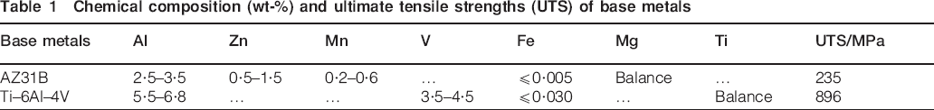
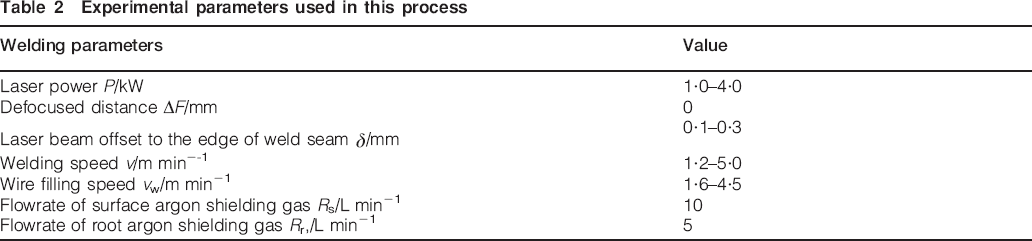
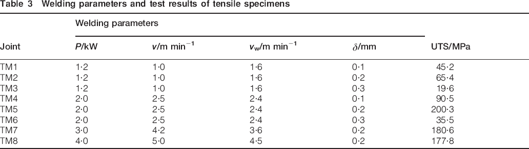
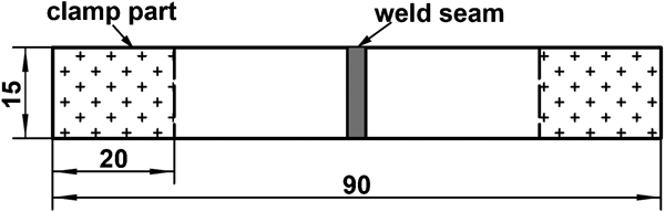
A 6 kW fibre laser (IPG YLR-6000) was employed in this experiment, which has wavelength of 1070 nm and beam parameter product of 6·9 mm mrad. The laser beam was transmitted by a 200 μm core diameter fibre and focused by a 250 mm lens. The focus spot diameter of the laser beam is ∼0·4 mm. The base materials used were Ti–6Al–4V alloy and AZ31B wrought Mg alloy, both with the thickness of 2·0 mm. The specimens were milled at the size of 100×50 mm for butt joining. Table 1 shows the chemical compositions and mechanical properties of the base metals, and Table 2 shows the main parameters and their values used in the present study. It should be pointed out that to avoid the underfill defects resulting from the vaporisation of Mg, a filler wire was used in this study. The filler wire was AZ31B Mg alloy with diameter of 1·0 mm. For different laser powers and welding velocities, the wire filling speed had been optimised to get the full joint. The welding parameters of the metallurgical and mechanical property tests are shown in Table 3. Figure 1 shows the schematic diagrams of the experimental set-up, where a laser beam is irradiated on the AZ31B side of the joint with an offset δ to weld seam. The welding was carried out by a square butt joint. The joint root gap was opening, but a root shielding gas was used to prevent it from oxidising.
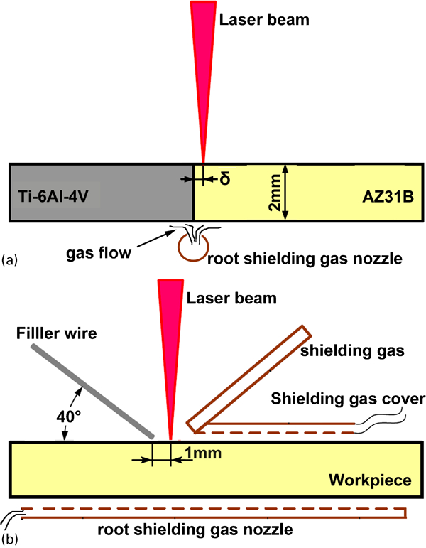
Schematic diagrams of experimental set-up
Chemical composition (wt-%) and ultimate tensile strengths (UTS) of base metals
Experimental parameters used in this process
Welding parameters and test results of tensile specimens
Before welding, the specimen surface was rubbed by sand paper to remove the oxide film and degreased by acetone. After welding, the joints were cut to prepare the metallurgical and tensile specimens. The metallurgical specimens were polished and etched by a solution of 4·2 g picric acid, 10 mL acetic acid, 10 mL water and 100 mL ethanol for 20 s. The bead shape, the microstructure and the fracture surface were examined by optical microscopy and SEM. The chemical compositions were observed by energy dispersive spectroscopy (EDS) technique. Figure 2 shows the dimensions of cross-weld tensile test specimens, which were performed on a 250 kN servohydraulic machine operated in ram displacement control at room temperature and with a nominal strain rate of 0·2 s−1. In addition, the tensile results were the average of three samples. In addition, the materials on the fracture surface at Ti side were scraped by a file and tested by X-ray diffraction (XRD) technique to reveal the phase structure in the interfacial layer.
Schematic drawing of tensile specimen
Results and discussion
Bead shape
The joint surface appearances are shown in Fig. 3. The uniform bead surface without metallurgical defects, indicating a stable process, is obtained at δ of 0·2 mm. However, the voids appear as δ decreases to 0·1 mm, and the two metals are even not joined as δ is zero. The bead shape is also uniform as δ increases to 0·3 mm, but the undercut appears at the toe of Ti side of the joint due to the lack of filler materials at this area, which is caused by the too big deviation of the filler wire.
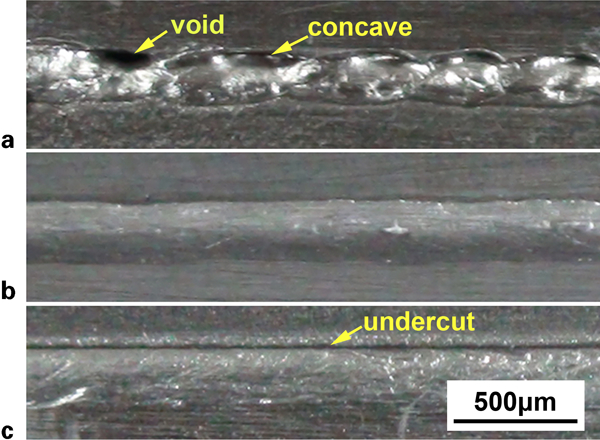
Surface appearances of typical joints (from top Ti–6Al–4V to bottom AZ31B): a TM4, b TM5 and c TM6 with δ of 0·1, 0·2 and 0·3 mm respectively, and other parameters are P of 2·0 kW, v of 2·5 m min−1 and vw of 2·4 m min−1
As shown in Fig. 4, the full joints are obtained by the optimal δ of 0·2 mm and relatively high laser power (⩾2·5 kW). When δ increases to 0·3 mm or the laser power reduces to 1·2 kW, as shown in Fig. 4b and c, the Ti/fusion zone (FZ) interface changes from a curve to a line. The curve Ti/FZ interface is deviated from the initial interface shown in Fig. 4a, indicating that Ti–6Al–4V is melted by the incident laser beam. The line Ti/FZ interface coincides with the initial Ti/Mg interface, as shown in Fig. 4b.
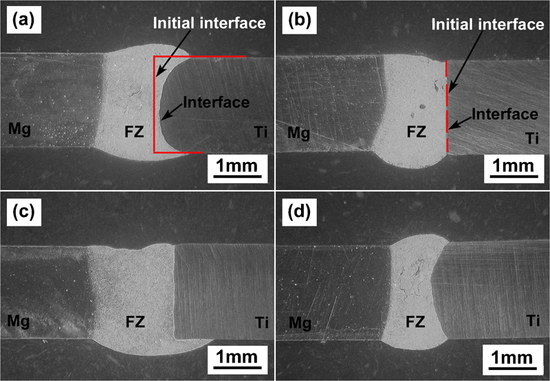
Cross-section morphologies of dissimilar Ti/Mg joints (from left AZ31B to right Ti–6Al–4V)
The above results show that the laser offset δ plays an important role in the bead shape and process characteristic. When δ is 0·1 mm, laser beam irradiates on the two alloys directly for the laser focus spot diameter is 0·4 mm. Then, a large amount of Ti–6Al–4V alloy is melted and enters into the weld pool by intense flow of liquid metal. Because the boiling point of Mg (1363 K) is lower than the melting point of Ti (1941 K), the vaporised explosion of Mg occurs easily when the liquid AZ31B is included by the Ti–6Al–4V during the intermixing of the two alloys. It leads to spatters, indicating bad process stability and weld voids, as sown in Fig. 3a. When δ is 0·2 mm, the laser beam almost irradiates on the AZ31B totally and just on the edge of Ti–6Al–4V. It means that the amount of melted Ti–6Al–4V is limited. The melted Ti can then be cooled and solidified by liquid AZ31B quickly rather than covering it to result in a vaporised explosion. As a result, the stable process and the uniform bead are obtained as shown in Fig. 3b. The curve Ti/FZ interface is caused by the melting of the initial Ti/Mg interface and the liquid metal flow in the weld pool. However, when δ increases to 0·3 mm, the laser beam irradiates on AZ31B totally. Because the power density of the laser beam reaches the biggest at the centre and then decreases dramatically,24 the laser power density at the initial Ti/Mg interface is insufficient to melt the Ti–6Al–4V at this time. Then, the final Ti/FZ interface keeps the initial state as a line.
Microstructure characterisations
Figure 5 shows the microstructure of the different areas of the typical joint. As shown in Fig. 5b, the microstructure of the AZ31B base metal is composed of massive grains. The FZ is mainly composed of equiaxed dendrite α-Mg within some secondary particles, as shown in Fig. 5c and e, which is similar with that of laser welded AZ31B magnesium alloy.25 Furthermore, some irregular linear structures are found in the FZ, as shown in Fig. 5d and e.
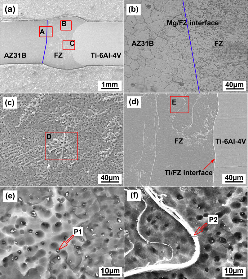
Microstructure of typical joint TM5 with P of 2·0 kW, v of 2·5 m min−1 and δ of 0·2 mm
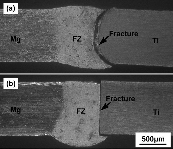
The EDS results in Table 4 show that point P1 contains 8·4 wt-%Al, 7·36 wt-%Zn and 4·87 wt-%O, while point P2 contains 22·8 wt-%Al, 33·18 wt-%Ti and 6·49 wt-%O. The O element may come from the oxidisation of the metallurgical sample surface during corrosion. Because the Ti element is more active, the linear Ti rich structure contains more O element. According to the analysis of Quan et al., 26 the secondary particles in α-Mg will include the intermetallic compound Mg17(Al,Zn)12. Since the linear structure is rich in Ti element, it will be formed by the intermixing of liquid AZ31B with melted Ti–6Al–4V. By the binary Mg–Ti phase diagram shown in Fig. 6a, it can be found that Ti will be first solidified totally when the pool temperature is higher than 650°C. Since the formation of Ti3Al needs a delay time, it is usually hard to be formed during the welding with fast solidification rate.27 After the melted Ti was solidified, the areas near its surface will be rich in Al element due to the disequilibrium segregation.28 As the pool temperature decreases to 650°C, α-Mg begins to nucleate and grow up on the solid Ti–6Al–4V. As the temperature is below 437°C, the Mg–Al eutectics (α-Mg+Mg17Al12) are precipitated from the α-Mg with high Al content. As a result, the linear structure will be composed of α-Ti, α-Mg and Mg–Al eutectics.
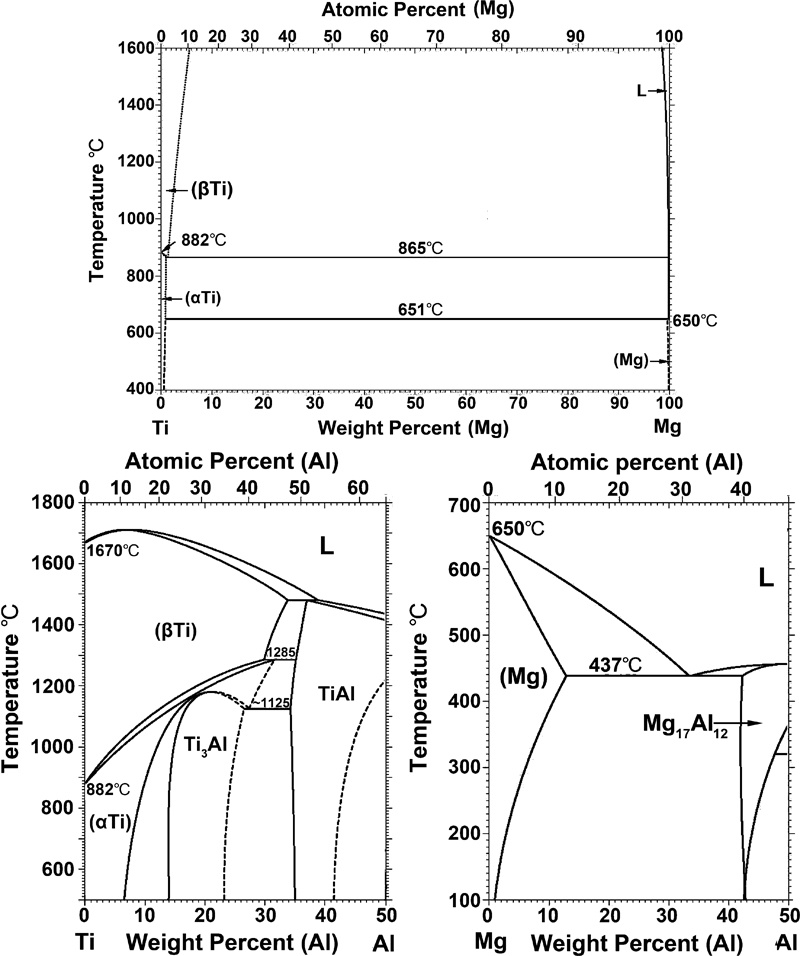
Binary diagram of a Mg–Ti, b Al–Ti and c Al–Mg
Interfacial layer
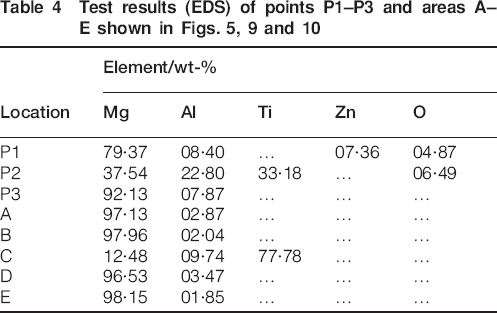
As shown in Fig. 7, a Ti/FZ interfacial layer is found in the joint, which is hardly observed by the naked eye. In the interfacial layer, the Ti and Mg elements change gradually, but the Al element concentrates. In addition, the width of the interfacial layer increases with decreasing laser offset as the other welding parameters are constant. It is ∼5·4 μm as δ is 0·2 mm, while it is only 1·9 μm as δ is 0·3 mm. Because decreasing δ increases the temperature and reaction diffusion time of the interfacial layer,14 the small δ obtains a thick interfacial layer. The nature of the interfacial layer will be discussed in the following by the fracture behaviours.
Interface characteristics of typical joints: other parameters are P of 2·0 kW, v of 2·5 m min−1 and vw of 2·4 m min−1
Joining strength
The UTSs of cross-weld samples are listed in Table 3. The maximum joining strength reaches 200·3 MPa, which is 85·1% of the Mg base metal. It is worth noticing that the high UTS is only achieved at δ of 0·2 mm, or else it reduces rapidly due to the metallurgical defects shown in Fig. 3 or the thin interfacial layer shown in Fig. 7. When the laser power increases to 2·0 kW or higher, high joining strength can be obtained at δ of 0·2 mm, the minimum of which reaches 177·8 MPa. However, the low laser power only gets the poor joining strength whatever δ is. For the laser power of 1·2 kW, the maximal joining strength is only 65·4 MPa.
Fracture morphologies
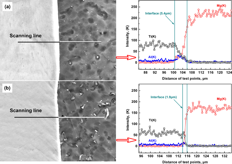
All the joints were fractured at the Ti/FZ interfacial layer, as shown in Fig. 8, indicating that it is the weakest area of the joint. In addition, the elastic modulus and the yield strength of Ti–6Al–4V at room temperature are 109 GPa and 870 MPa, while those of AZ31B are 40 GPa and 157 MPa respectively. These big differences in elastic modulus and yield strength may cause the strain concentration at the Ti/FZ interface. It also leads to the fracture at the interfacial layer.
Macrofracture location of typical joints: other parameters are P of 2·0 kW, v of 2·5 m min−1 and vw of 2·4 m min−1
Figure 9 shows the joint fracture morphologies at Ti side. The fracture surface consists of both scraggly and smooth areas, as shown Fig. 9a–c, and the proportion of smooth areas to the whole fracture surface increases with decreasing joining strength. For the joint TM6 with UTS of 35·5 MPa, the fracture surface almost totally consists of large smooth areas, but for the joint TM5 with the biggest UTS, it almost only consists of scraggly areas. As shown in Fig. 9d and e, the scraggly area of the joint with high UTS is characterised by equiaxed dimple patterns accompanying a few lamellar tearing, while that with poor UTS is only characterised by lamellar tearing. Table 4 shows that areas A and B in Fig. 9d and e only consist of the Mg and Al elements. It suggests that the scraggly area is the AZ31B Mg weld metal remaining at Ti side. The EDS result of area C shows that the smooth area consists of 77·78 wt-%Ti and 12·48 wt-%Mg, indicating that it is the Ti surface but with little remaining Mg weld metal.
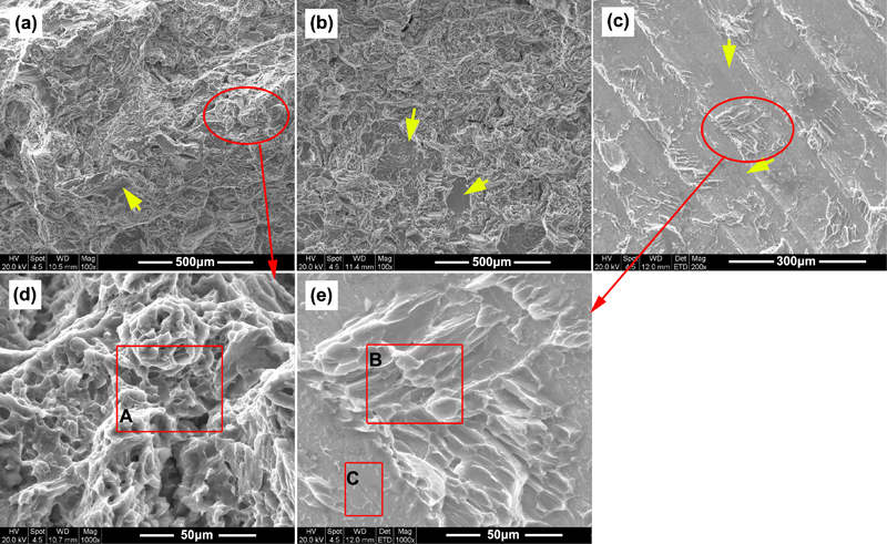
Images (SEM) of fracture surface at Ti side: arrow refers to smooth area
Figure 10 shows the joint fracture morphologies at the Mg side, which are good corresponding to those at Ti side. The fracture of the joint with high UTS is characterised by a scraggly appearance consisting of dimples and some lamellar tearing, as shown in Fig. 10a and b, while that with poor UTS is characterised by large smooth areas with a small amount of lamellar tearing, as shown in Fig. 10c and d. The EDS results of areas D and E show that either the scraggly or the smooth area consists of only Mg and Al elements, and their contents are similar with that in AZ31B Mg alloy. It indicates that there is no remaining Ti at the Mg side. In addition, it can be seen that the smooth area consists of obvious cellar grain patterns with some white linear structure, as shown in Fig. 10d. The EDS analysis of point P3 shows that it contains higher Al element (7·87 wt-%) compared with Mg base metal. According to the Mg–Al and Ti–Al phase diagram, as shown in Fig. 6b and c, both of the intermetallic compounds Ti3Al and Mg17Al12 may form in the Ti/FZ interfacial layer. However, in Fig.11, the XRD results of the fracture surface at the Ti side show that only Mg17Al12 was found. The formation of Ti3Al is limited by the fast solidification of the Ti alloy at the interface because the formation of Ti3Al needs a delay time.27
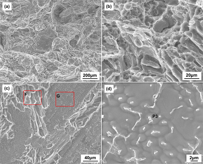
Images (SEM) of fracture surface at Mg side
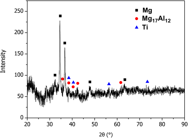
Test results (XRD) of fracture surface at Ti side of joint TM5
Interfacial layer growth and joining mechanism
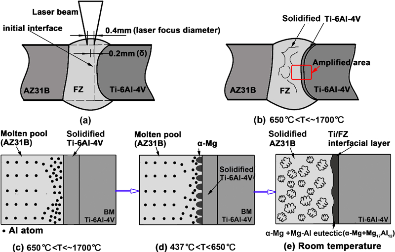
By the interfacial layer characterisation and joint fracture morphologies, the Ti/FZ interface growth mechanism can be summarised as shown in Fig. 12.
Schematic diagram of interfacial layer growth mechanism
In the case of acceptable joint TM5, δ has the optimal value of 0·2 mm, and the edge of the laser beam irradiates on the Ti side, as shown in Fig. 12a. Then, some Ti at the initial interface is melted by the laser beam. When the molten pool temperature is below ∼1700°C but higher than 650°C, according to the phase diagram in Fig. 6a, the melted Ti, including those involved in the molten pool, is solidified first by the cooling of liquid AZ31B, as shown in Fig. 12b. At this period, a large amount of active Al atoms segregate at the front of the liquid/solid interface due to disequilibrium segregation, as shown in Fig. 12c. On the other hand, the Al atom prefers to migrate from the Ti surface to weld pool according to Fick's first diffusion law because the Al content of Ti–6Al–4V is higher than that in AZ31B.29 This is also in favour of the segregation of the active Al atom at the front of the liquid/solid interface. This is why obvious Al concentration had been observed in the interfacial layer, as shown in Fig. 7. When the pool temperature decreases to 650°C or lower, the liquid AZ31B begins to react with the active Al atom to form the α-Mg with high Al content first at the liquid/solid interface, as shown in Fig. 12d. As the temperature further decreases to 437°C or below, the intermetallic compound Mg17Al12 will precipitate to form the Mg–Al eutectic (α-Mg+Mg17Al12) in the interfacial layer. As a result, the interfacial layer is composed of α-Mg and Mg–Al eutectic.
When δ is larger than 0·2 mm or the laser power reduces to 1·2 kW, the power density at the initial interface is insufficient to melt the Ti–6Al–4V, which can be proved by the truth that the final Ti/FZ interface coincides with the initial Ti/Mg interface, as shown in Fig. 4. It indicates on the Ti/FZ interface that there are only a few scattered locations dissolved by the liquid AZ31B with some active Al atoms. Moreover, the insufficient heat increases the solidification rate and shortens the growth time of the interfacial layer. Consequently, after the weld solidified totally, the large amount of α-Mg only attaches on the solid Ti surface rather than forms the Mg–Al eutectic by reacting with the Al atom. It can be testified by the SEM image shown in Fig. 10d, where many cellar grains but without Al rich structures appear in the smooth fracture area.
According to the nature of the Ti/FZ interfacial layer discussed above, it can be found that for acceptable joints with δ of 0·2 mm, the interfacial layer is a semimetallurgical joining with high joining strength due to the reaction of liquid AZ31B with the active Al atom. However, the interfacial layer of the joints with bad joining strength is mechanical joining, which is mainly joined by the van der Waals force because of the lack of reaction. During tensile test, most of the weld metal is detached off the Ti surface directly rather than fractured in the interfacial layer, which resulted in large smooth areas in the fracture surface, as shown in Figs. 9c and 10c.
Conclusions
Laser welding with Mg filler wire was developed to join dissimilar Ti/Mg alloys using a fibre laser. The acceptable joints without metallurgical defects were only obtained at the optimal laser offset δ of 0·2 mm from the edge of the weld seam 0·2 mm to the AZ31B side of the joint.
By the intermixing of the melted Ti alloy with the liquid AZ31B Mg in the weld pool, some irregular linear structures rich in Ti and Al element were formed in the FZ.
The discussion on the interface growth mechanism showed that the interfacial layer of acceptable joint was composed of α-Mg and Mg–Al eutectic, while that of bad joint mainly consisted of α-Mg, which attaches on the solid Ti surface directly.
All the joints were fractured at the Ti/FZ interface. The maximum cross-weld UTS of the joints reached 200·3 MPa, which is 85·1% of the AZ31B base metal. When δ increased from 0·2 to 0·3 mm or the laser power reduced to 1·2 kW, the Ti/FZ interface changed from a curve to a line, and its joining mode also changed from a semimetallurgical joining with high UTS to a mechanical joining with poor UTS.
For the joint with acceptable UTS, the fracture surface at the Ti side was characterised by the remaining weld metal with scraggly appearance, while for the joint with poor UTS, it was mainly characterised by the Ti surface with smooth morphology.