
Abstract
The aim of this paper is to investigate the joint strength of adhesive bonding, friction stir spot welding (FSSW) and hybrid joining as FSSW–adhesive bonding on lap joints of polypropylene plates separately. In addition, the different overlap configurations were studied. The FSSW and weld bonding had higher joint strengths than adhesive bonding, but the FSSW joint was the highest. It reached 93% of the base material strength for the configuration of welded type 2 design.
Keywords
Introduction
Friction stir spot welding (FSSW) is a derivative of the friction stir welding process, which was developed in 1991 by the British Welding Institute (The Welding Institute).1– 8 The FSSW process was first used in the production of RX-8 model by Mazda in 2003.4 The process for overlapped joints of aluminium, magnesium and other lightweight metals was also developed by Kawasaki Heavy Industry.4, 9, 10 Ford worked intensively on this technology for further advances.3 A spinning cylindrical pin with a stepped shoulder is pressed against the seam line of the two parts to be welded in the process. The process is extremely simple. The FSSW process consists of three phases: plunging, stirring and retraction.1– 4, 7–13 The welding cycle begins when the pin plunges into the upper sheet of the lap joint. The plunge load is supported from the bottom side with a backing plate or anvil to sustain the plunging load.3, 10, 12, 13 Then, in the beginning of the stirring stage, the rotation of the tool first softens the material by means of frictional heat. Much more heat is generated to further soften a large region of the material underneath the tool shoulder after the tool shoulder contacts the top surface of the upper sheet. The softened material moved at rotation and axial directions in the periphery of the pin.1, 2, 10, 12 Thus, the softened material is pushed and stirred to form the metallurgical bond around the rotating pin. At the retraction, which is called off last stage, the tool and the pin are withdrawn after the joining is completed.7, 10 Although the FSSW was studied abundantly for the lap joints of metallic materials,3, 4, 7, 10– 13 the interest on the FSSW of polymeric materials is increasing.1, 2, 14, 15 One of the goals in our study is to investigate the suitability of FSSW process for polypropylene material, which is a preferable polymer in the industry.
Bilici et al. 14 studied the FSSW parameters for high density polyethylene sheets. It was noted that the dwell time was the most dominant welding parameter for weld strength followed by the tool rotation speed. Oliveira et al. 15 studied the feasibility of friction spot welding of thermoplastics on poly (methyl methacrylate) plates, and their preliminary results had shown that the weld strength was comparable to other available welding techniques, while the joining times were equal or shorter. Mitlin et al. 4 pointed out that photographs of the failure surfaces of the lap shear samples joined with FSSW at different pin insertion depths. The tensile force values of the samples were examined. The effects of pin insertion depth on the failure mode of the lap shear samples were determined. There was a marked change in the failure mode with increasing tool penetration depth. As the depth increases, the failure location shifts further away from the pin, towards the base material.
The methods to join thermoplastic materials are divided into three groups, which are mechanical fastening, adhesive bonding and welding. Mechanical fasteners could join two components quickly, but they did not provide a leak tight joint, and the localised stresses might cause them to pull free of the polymeric material.16 Adhesive bonding is inherently preferable to mechanical fastening because of the continuous connection avoiding large stress concentrations induced at each discrete fastener hole.17 However, the difficulties about the surface preparation and the time to cure limited the adhesive bonding.16, 17 Petrie18 pointed out that the joining of plastics with adhesives could be difficult because of the substrate's low surface energy and the presence of weak boundary layers associated with mould release and additives. In addition, adhesive bonding was a relatively slow process that could be a significant drawback in many industries that produce high volume plastic assemblies.18 Weld joining eliminates the stress concentrations created by holes required for mechanical fasteners and reduces the processing times.17 Arıcı and Sınmazçelik16 indicated that welding could be used to produce bonded joints with mechanical properties that approach those of the parent material. Anık et al. 19 referred to the difficulty of the joints with reverts or bolts due to sensitivities of plastics against the notch, and it was pointed out that adhesive and welding came forward as the methods of thermoplastics joining. At the same time, the combined connections (bonded–welded, bonded–riveted and bonded–screwed) were increasingly studied by researchers, too.20– 22 The weld bonding process is essentially the spot resistance welding of parts that subsequently have their overlapping areas adhesively bonded.21, 23 It is known that lap joints usually carry larger loads because of the larger bonding areas compared with butt joints.24, 25 The advantages of high static strength, improved fatigue strength and improved corrosion resistance were pointed out for weld bonding.20, 21, 23
The aim of this paper was to investigate the joint strength of adhesive bonding, FSSW and weld bonding as FSSW–adhesive bonding on lap joints of polypropylene plates separately. In addition, the different overlap configurations were studied. Tensile tests were applied to the related joints. Fracture cross-sections were examined with an optical microscope.
Experimental
The dimensions of polypropylene sheets used in lap joints were (3×30×150) mm, in accordance with the TS EN 12814-2 standard. The examined three types of overlapping joints are given in Fig. 1. The lap distance was 30 mm. Polypropylene sheets were joined by FSSW, adhesion bonding and weld bonding (FSSW–adhesive bonding).
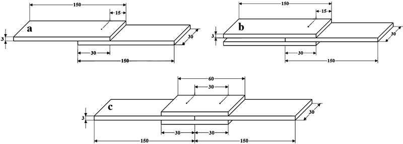
Overlapping types
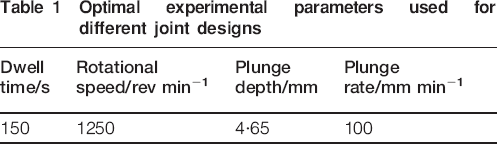
The FSSW tool, which was made from 4140 steel, had a shoulder diameter of 20 mm, a pin diameter of 7 mm and a pin length of 4·25 mm. The plunging, stirring and retraction phases mentioned above were applied by the tool at the centre of the overlapping region. There were one, two and four welding points in types 1, 2 and 3 respectively. The related values used in welding are given in Table 1. Henkel Company products of Primary PP33 and Loctite 406 glue were used for adhesive bondings.
Optimal experimental parameters used for different joint designs
An Instron 4411 testing machine was used for the tensile tests. The tensile test speed was 20 mm min−1. The distance between the jaws was 180 mm. The tensile tests were carried out at least three times. Both surface appearances occurred after welding, and failure regions after tensile tests were photographed as a macro. In addition, optical electron microscopy observation was performed for the fracture surfaces and cross-sections of samples.
Results and discussion
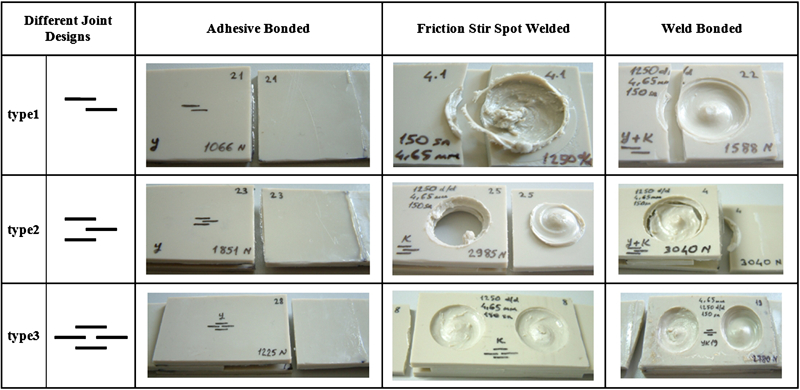
The photographs of all the joined samples before the tensile test are given in Fig. 2. The formation and the physical form of the welded points were examined by naked eye. The welding points of all the samples were plastered like slurry or mud. The resulting weld had a characteristic hole in the middle of the joint. In addition, the peak of the material was determined after the retraction of the tool. The spiral mixture traces, which were represented as material drifts around the pin at the welding region, were seen clearly at the welding points. A bit of softened material ran away from the welded region. Thus, the formation of burr surrounding the shoulder of the tool was in question. There were no colour differences (colour match) between the welding region material and the base material.
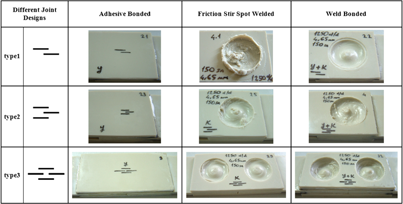
Photographs of samples before tensile test
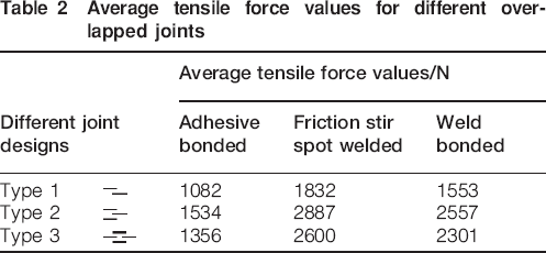
The tensile force values for different overlapped joints are given in Table 2. It is seen that the welded samples had the highest tensile forces while the adhered samples had the lowest for all the joint design types. At the same time, it is also said that the type 2 design gave the highest tensile forces, while the type 1 design gave the lowest. Therefore, the highest tensile force was obtained as 2887 N for welded with type 2 design. This value is equivalent to 93% of the base material, which was obtained as 3090 N. It was thought that the participation possibility of adhesive material to the welding material caused a decrease in the tensile forces for weld bonded samples. Both the welding area and the welding volume region directly affected the joint strength. The increase in these values caused an increase in the tensile forces. The area that carries the tensile load was bigger for types 2 and 3 designs than type 1 design. It is also noted that the area is changed with the welding parameters of dwell time and plunge depth, too.
Average tensile force values for different overlapped joints
The tensile curves of type 2 samples are given in Fig. 3. It was obtained that the tensile elongation values of the three joint methods were dramatically decreased when compared with the base material. However, it was seen that weld bonding affected the tensile elongation positively, and the values reached a much higher point than the FSSW joints.
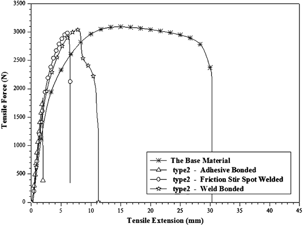
Variation in tensile extension with tensile force for samples obtained using highest tensile force values
The failures observed from the broken samples of FSSW joints were classified into three modes by some researchers.1, 2, 4, 12 The failure that occurred around the pin was called the first failure mode (mode 1). The failure that occurred around the shoulder was called the second failure mode (mode 2). The failure that occurred at the base material edge of the welding region interface of the upper sheet was called the third failure mode (mode 3). The macro photographs of failures for all joints are given in Fig. 4. These images were determined by the relation between the failure and the joint strength. In the adhesion bonded samples, the failure occurred at the adhered line for each type of joint. Modes 2 and 3 were seen for types 1 and 2 of FSSW and welding bonded joints. The type 3 of FSSW and weld bonded joints show a different failure mode of crack formation. The crack propagated completely in the base material.
Photographs of samples after tensile test
The optical microscope images are given in Fig. 5 for the welded type 2 and 3 designs. The tensile extensions were observed, which developed in the perpendicular direction to the plane of the page and the tensile direction. It is seen clearly from the failure surfaces given in Fig. 5a–c that the elongations at the upper and lower regions represented the ductile fracture. Tensile extensions were rather intensive at type 3 in the sample of FSSW, and prolonged fibres that represented the ductile fracture and tensile extensions were observed. The prolonged fibres were seen much more clearly in Fig. 5e and f. These elongation fibres also caused prolonged tensile test. The white regions that indicated ductility were intensive for these samples.
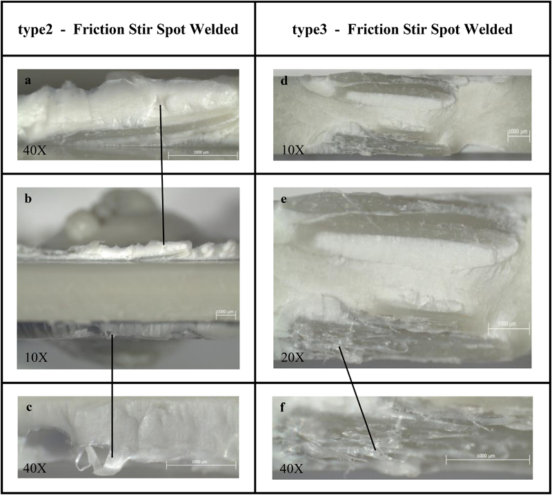
Optical microscope images for type 2 and 3 joints with FSSW
The optical microscope images are given in Fig. 6 for weld bonded type 1, 2 and 3 designs. The tensile elongations were not intensive at type 1. Small amounts of elongations and white regions are seen in Fig. 6a and b. There were traces of ductile fracture in the sample surface. However, it is seen that brittle fracture was dominant. The tensile elongations that developed at the tensile direction were seen for type 2. The white regions were intensive. The elongations were seen very clearly in Fig. 6c–e. It is seen from Fig. 6c that many strands of fibres were observed at the left side of the failure surface. The failure surface of type 3 design occurred at the base material.
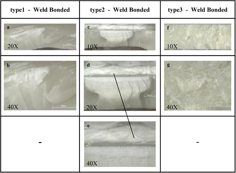
Optical microscope images for welding bonded joints of types 1, 2 and 3
The cross-section appearances of the welding area for FSSW type 1 design, which had a single welding point, are seen in Fig. 7. In addition, the cross-section appearances of welding area for FSSW type 2 and 3 designs, which had double welding points, are seen in Fig. 8. These welding points were mutual and first part of A, and then parts of B were formed as welding points in these joints. It was noted that the end region of the welding area of A was softened again and mixed to part of B at the common welding area. The distinction lines separating the polypropylene sheets are seen clearly at the edges, but these lines disappeared at the welding area.
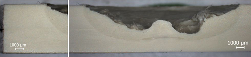
Cross-section image of single point welding in optical microscope
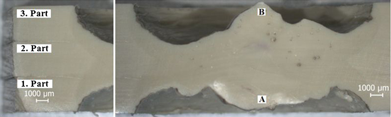
Cross-section image of double point welding in optical microscope
Conclusions
Lap joints were created with adhesive bonding, FSSW and weld bonding. The FSSW and weld bonding had higher joint strengths than adhesive bonding, but the FSSW joint was the highest. The type 2 design gave the highest strength compared to the other designs. It reached 93% of the base material strength for the configuration of welded type 2 design. After welding, no colour change was observed between the welding region material and the base material, which showed that there was no deterioration in the welding region material. This was a positive indicator for the situation of welding. Mode 1, which indicates a weak joint, was obtained in none of the FSSW and weld bonded samples. The crack propagated completely in the base material for type 3 design. In adhesive bonded samples, the failure occurred at the adhered line.
Footnotes
Acknowledgements
The authors are grateful for the support provided by the Kocaeli University Rectorship (project no. 2007/043).