
Abstract
Modified 9Cr–1Mo steel plates of 6 mm thickness have been laser welded using CO2 laser. The effects of beam intensity and overall heat input (168-1500J/mm) on the bead characteristics, microstructure and mechanical properties of the welds have been investigated by varying the laser welding parameters such as laser beam mode, power and welding speed. The microhardness survey carried out on the welds after post-weld heat treatment did not reveal any soft zones in the intercritical heat affected zone for welds made with a heat input of up to 420 J mm−1. The tensile strengths of the welds were comparable to that of the base material. Charpy impact tests on subsize specimens revealed that the welds have good toughness. δ-Ferrite was observed in the fusion zone of the welds made at heat input of 700 J mm−1 and above, the content of which increased with the increased heat input.
Introduction
P91 steel classified as creep strength enhanced ferritic steel has good thermal fatigue resistance compared to low alloy materials like P22. It has a martensite start temperature of ∼400°C and a martensite finish temperature of 200°C1 and is generally supplied in normalised and tempered condition with a microstructure consisting of prior austenite grains containing lath-like tempered martensite. The alloy has high dislocation density stabilised by Cr23C6 carbides, carbonitride and nitrides of Nb and V. 1 1,2 However, in order to use this alloy in welded form, there are several weldability issues requiring attention. One of the major problems is the formation of delta ferrite in the fusion zone (FZ), which is favoured by the presence of high amounts of chromium (>9%) and Si (>0·5%), adversely affecting toughness and creep ductility.3 Owing to the high alloy content and hardenability, the steel is also prone to cold cracking or hydrogen induced cracking.4 Maintaining a suitable preheat (∼200°C) and interpass temperature (in case of multipass welding) during welding helps in minimising these problems. The preheating temperature should be maintained below the martensite finish temperature to complete the transformation after welding. Sufficient interpass temperature allows hydrogen ejection out of the welds. However, an upper limit of 370°C is recommended to avoid hot cracking.5 Welds should also be subjected to post-weld heat treatment (PWHT) to temper the martensitic structure formed in both the weld metal and the heat affected zone (HAZ). The upper limit for PWHT temperature should be <Ac1 to avoid the formation of fresh martensite or soft ferrite after PWHT. It is in the range of 750–770°C.6, 7 In that part of the HAZ, where the peak temperature experienced is between Ac1 and Ac3 [intercritical HAZ (ICHAZ)] or just above Ac3 (fine grained HAZ), carbides do not dissolve completely in austenite during the heating part of the weld thermal cycle; and during PWHT, they coarsen, resulting in the loss of strength in these zones.5, 8– 11 These areas are more prone to creep rupture, and fracture occurs in this part of the HAZ, with rupture life far below that of the base metal (BM) called Type IV cracking.
Although arc welding is the most widely used process for joining this class of steels, the power beam process, like electron beam welding, has been shown to increase the creep strength of the HAZ due to the localised nature of the welding process. Lee et al. have studied the effect of various tempering temperatures on the mechanical properties of laser welds.12 Accordingly, it was felt that the laser welding process can be advantageously used to weld this alloy as welding can be accomplished at greatly reduced heat input, and the weld area can be effectively shielded easily as the welding spot is very small. While effective shielding can be useful in reducing hydrogen induced cracking, low heat input and high cooling rates compared to arc welding can minimise HAZ grain coarsening, avoid the formation of soft intercritical zone and consequently minimise or avoid type IV cracking in service. However, there are no systematic studies reported on the autogenous laser welding of P91 in a wide heat input range vis-à-vis formation of different metallurgical features.
In the present work, laser welding studies have been carried out on 6 mm thick P91 steel in autogenous mode using a high beam quality slab CO2 laser. The effect of laser welding parameters on the mechanical properties and intercritical zone has been reported.
Experimental
Preparation and inspection of weld pads
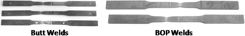
Welding experiments were carried out using a DC035 slab CO2 laser on 6 mm thick P91 steel with chemical composition of Fe–9·53Cr–1·01Mo–0·23Nb–0·18V–0·15C–0·35Mn–0·35Si–0·07P (wt-%). The beam was used in both Gaussian and donut modes and focused using a 300 mm focal length mirror. The laser beam spot sizes obtained were 180 and 360 μm in Gaussian and donut modes respectively. Laser welding parameters were identified through bead-on-plate (BOP) experiments. Argon at a flowrate of 30 L min−1 has been used as both plasma suppression and shielding gas in trailing mode with 45° nozzle angle. Shielding nozzle standoff of 4·5 mm gave effective plasma suppression, and placing the laser beam focal plane 2 mm inside the material yielded better bead characteristics with less microporosity. Full penetration welds could be obtained for a range of parameters. Accordingly, the welding parameters could be so chosen to cover a wide range of heat input conditions, as listed in Table 1, and experiments were carried out. The first three experiments were with low heat input, and the second three were at higher heat input. Low heat input welds could be made in square butt configuration. However, the high heat input welds have to be in BOP mode only as there was severe melt dropout in these conditions. For butt welding, the edges have been prepared by surface grinding to achieve zero gaps between the abutting surfaces.
Welding parameters
All the welds were subjected to PWHT by heating at a rate of 2°C min−1 up to 760°C and holding for 3 h. The welds were subjected to dye penetrant testing and X-ray radiography according to the ASTM E94 and E1416 standards.
Metallography
Transverse weld cross-sections were hot mounted and polished following standard metallographic procedures and etched using Villella's reagent. The macrostructures of the weld cross-sections were taken using an Olympus stereo microscope and microstructures using optical and scanning electron microscopes.
Microhardness survey
Microhardness measurements were taken across the butt welds using a UHL automatic microhardness tester at a load of 200 g with the indentation time of 15 s and inter-indent gap of 150 μm. In the welds prepared with high heat input, the hardness survey was carried out by starting from the middle of the weld. Such survey was carried out at three locations from top to bottom of the welds to thoroughly check the presence of any soft zone.
Mechanical testing
The welds were subjected to transverse tensile testing according to ASTM E8 using Instron 5584 at a crosshead speed of 1 mm min−1. Face and root bend testings were carried out according to ASTM E192. Room temperature Charpy impact testing was performed according to ASTM E23 for subsize specimen for both weld zone and BM. Two specimens were drawn from each weld, and four specimens in total were tested per parameter.
Results and discussion
Integrity of welds
Dye penetrant testing did not reveal any surface defects at both face and root of the weld, and radiography results showed that the welds were acceptable as per ASME section III, division NB. The bend tested samples are shown in Fig. 1. From the figures, it can be seen that both the face and the root of the welds have passed the 180° bend, confirming that the welds have sufficient ductility. The bend test results also confirm the X-ray radiography results that the welds are free from any internal defects. Defects of size <200 μm, which could escape the X-ray radiography, can open up during bend testing. Hence, sufficient bend ductility of both face and root of the welds qualifies the welds in terms of integrity.
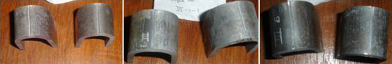
Bend test results
Macrostructures
The macrostructures of the welds made at different heat inputs are given in Fig. 2. The welds were free from defects like porosity and cracks. There is an increase in the width of the FZ and HAZ with increase in heat input. The FZ structure is coarser in high heat input welds than that in low heat input welds. Furthermore, the bead shape is highly concave with excess penetration in case of weld made with heat input of 1500 J mm−1.
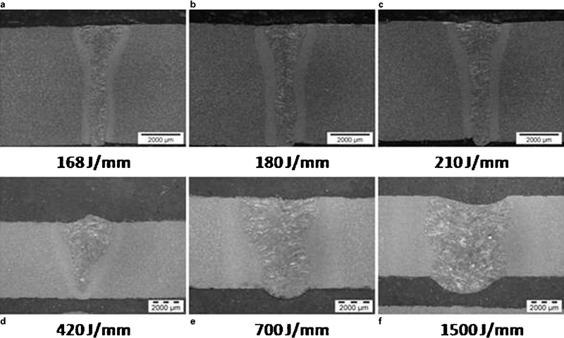
Macrostructures of welds
Microstructure
The SEM images of the BM and FZ of butt welds are given in Fig. 3, and the microstructures of the ICHAZ of two welds are given in Fig. 4. The microstructures of both BM and weld metal have typical tempered martensitic structure with carbides decorating both prior austenite and lath boundaries. However, for all the three heat inputs, the prior austenite grain size is smaller than that of the BM. The microstructure was uniform throughout the weld for particular welding conditions. No δ-ferrite was observed in any of the three welds. The microstructure of the HAZ was much finer than that of both BM and FZ (Fig. 4) and did not vary much with heat input in the chosen parametric range.
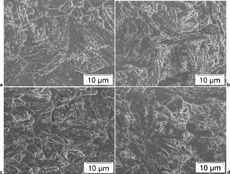
Microstructures of base metal and FZ
Microstructures of HAZ
High heat input BOP welds were prepared essentially to study the effect of heat input on the microstructures of FZ and HAZ. As expected, microstructural examination revealed that the prior austenite size of the FZ microstructure increased with the increase in heat input (Fig. 5). The FZ contained delta ferrite, which was absent in the butt welds made at low heat inputs, and its volume fraction increased with the increase in heat input from 700 to 1500 J mm−1. The Chromium - Nickel Balance (CNB) for this steel is <12, and δ-ferrite is not expected in the FZ, but the results show it is present in high heat input welds but not in low heat input welds. This could be explained based on the very narrow temperature range over which δ-ferrite is stable in the L+δ-ferrite phase field. According to recently published work,13 the temperature at which δ-ferrite nucleates from the liquid metal (liquidus temperature) is 1524°C, and the temperature range in which L+austenite+δ-ferrite is stable is only 13°C. Hence, it is quite possible that, at very fast cooling rates experienced, as in low heat input welds, δ-ferrite nucleation itself is suppressed, and solidification proceeds directly from liquid metal to austenite. Hence, no ferrite is found in the weld metal. In contrast, in high heat input welds, the cooling rate could be sufficiently low for δ-ferrite to nucleate from the molten metal but not slow enough for the complete transformation of this ferrite to austenite at lower temperatures.
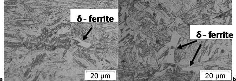
Microstructures showing δ-ferrite in FZ
Hardness of weld metal and HAZ
The microhardness profiles across the welds for butt welds are given in Fig. 6. The FZ microhardness is higher than both the base material and the HAZ. It varied between 260 and 280 HV in the FZ against BM hardness of 220–240 HV. The FZ, unlike the normalised and tempered BM, is having a cast structure in the as welded condition with all the alloying elements dissolved in the liquid metal during welding. Hence, the hardness of the as welded martensite formed in the FZ will be higher than that of the as normalised martensite of BM. Consequently, the tempering kinetics of these two martensitic structures could be different, hence the higher hardness in the FZ. No soft zones at both FZ/HAZ and HAZ/BM boundaries were observed. The reduction in hardness in ICHAZ is widely reported in conventional ferritic steel welds and is attributed to the partial transformation during the weld thermal cycle and the subsequent tempering of this zone during PWHT. The very high cooling rates of the laser welds make the width of the ICHAZ narrow, and the time available for transformation will be very less. As a result, hardness reduction in ICHAZ (HAZ/BM interface) is not observed.
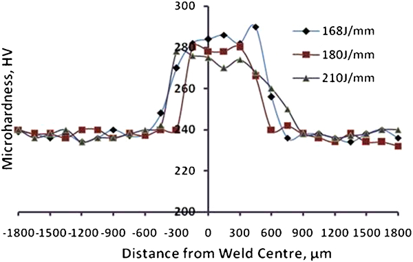
Microhardness profile across welds made using different heat inputs
The hardness profiles of high heat input welds are shown in Fig. 7. For the weld with heat input of 420 J mm−1, no dip in hardness is observed. However, for welds with heat input of 700 and 1500 J mm−1, there is a clear reduction in hardness in the ICHAZ. Further, the width of the soft zone also increased with the increase in heat input. It may be noted that the minimum hardness did not vary with heat input; it is typically <200 HV. It is clear that a high heat input results in an increase in the width of the HAZ and a decrease in the cooling rate. With the increase in HAZ width, the width of ICHAZ also increases, and with the decrease in cooling rate, the extent of transformations in ICHAZ increases. Hence, it can be concluded that, in the present set-up (beam spot sizes of 180 μm and 360 μm), the heat input up to 420 J mm−1, which is twice the required value to autogenously laser weld 6 mm thick plates, is tolerable without formation of any soft zone.
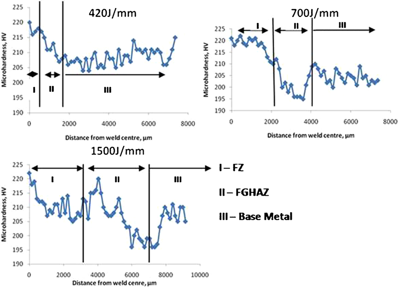
Microhardness profile (weld centre to BM) of welds made at high heat inputs
Tensile strength of joint
During tensile testing, fracture took place at a location away from the weld/HAZ, indicating that the welds are stronger than the base material. These results are in line with the microhardness survey results. The broken tensile test specimens are shown in Fig. 8. The welded specimens had an ultimate tensile strength of 688–717 MPa, which is comparable to the BM ultimate tensile strength of 700–715 MPa. The elongation of the weld joint (19–22%) is comparable to that of BM (20–22%), indicating that the laser welds have good ductility after PWHT. Owing to the difference in strength of the BM and the weld metal, a decrease in ductility during tensile testing of the weld joint was expected. However, the width of the FZ is narrow (1–2 mm), and the difference in hardness between the FZ and the BM is only ∼60 HV. These two factors reduce the restraining effect caused by the weld during tensile loading, and hence, the weld joints show almost a similar elongation as BM. It is also important to note that the heat input of the weld did not have any effect on the tensile properties of the welded joints. In spite of the variation in the hardness observed in the HAZ of high heat input welds, during tensile testing, fracture occurred in the BM with strength and elongation as obtained for low heat input butt joint welds.
Tensile tested specimens
Impact toughness
The results of the Charpy V-notch impact tests are given in Table 2. It is clear that, for all the welds, irrespective of the heat input, the toughness is more than that of the BM.
Impact values
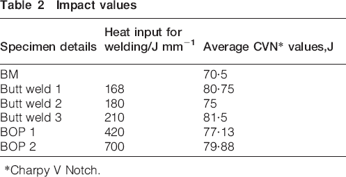
*Charpy V Notch.
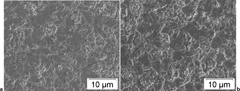
The high values of impact toughness could be due to the finer microstructures obtained with laser welding. It is important to note that even with some volume fraction of δ-ferrite present in the weld metal, the high heat input welds have toughness similar to that of the low heat input welds. Fractographs of the BM and welds made with different parameters are shown in Fig. 9. The dimples indicate ductile failure in both BM and welds. The size of the dimples observed in the fracture surface of BM specimens is larger than those observed on the fracture surface of the weld specimens, indicating that the fine microstructure of the welds contributes to the improved toughness of the weld metal.
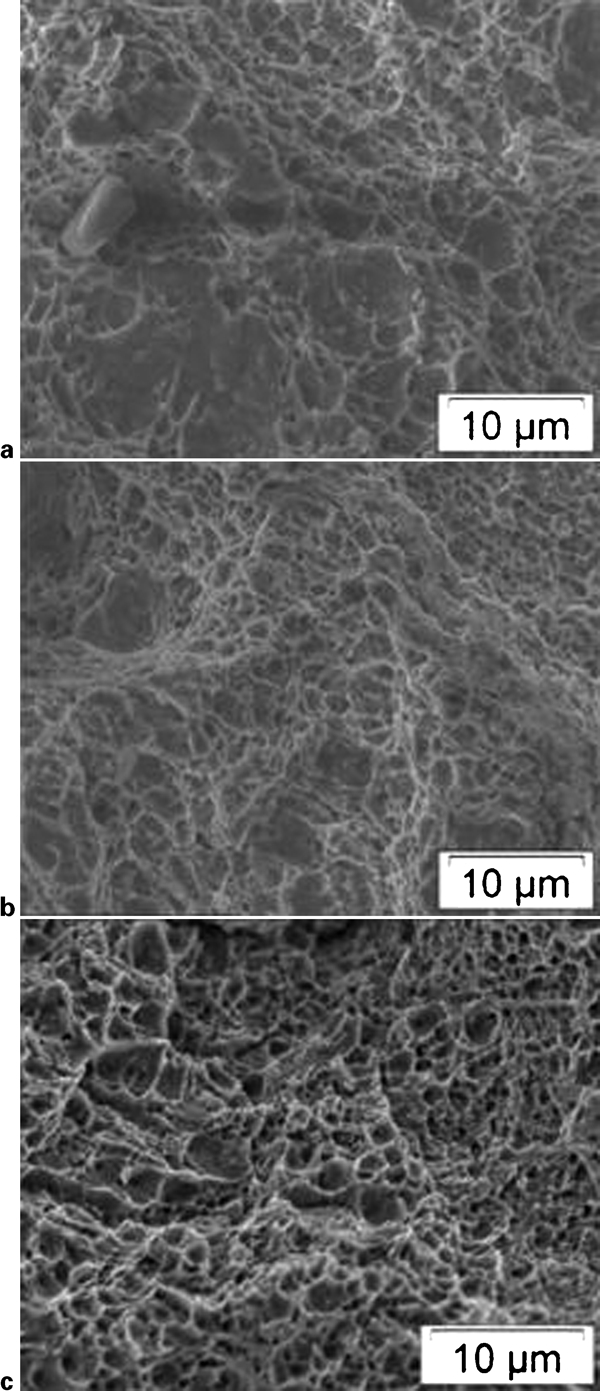
Fractographs of impact tested specimens
The good impact toughness of the weld metal after PWHT, which is comparable to that of BM, is important because the toughness of the weld metals produced by arc welding processes, like shielded metal arc welding, submerged arc welding and flux cored arc welding processes, are poor. 14 14,15 Many fabrication codes insist on minimum toughness for weld metal, and it is often difficult for consumables produced for these welding processes to meet this requirement. Nickel, an element known to decrease the creep strength of these steels, is added in the welding consumables with an objective of improving the toughness. Only the consumables produced for the gas tungsten arc welding process meet these toughness requirements without any difficulty as this welding process does not use flux. However, being a process with very low deposition rate, it is used mainly for welding thin section components, and for joining thick sections, one has to modify it with expensive welding automation to achieve reasonable weld deposition rates. In this context, the use of lasers for welding thick sections of P91 steels offers advantages of simpler edge preparation, high welding speed and good toughness.
In addition to the results presented and discussed above, the present study brings out two important points that can be useful with respect to welding high Cr ferritic steels in general. One is the possibility of using welding processes like laser or Electron Beam (EB) welding to minimise type IV cracking in these steels. It is well known that type IV cracking is caused by the poor creep strength of the outer regions of the HAZ (ICHAZ and fine grained HAZ ) of the welds compared to rest of the weld joints. Cracking is also contributed by the triaxiality that is developed due to the stress mismatch that exists in the weld.16 The present results have shown that, using appropriate welding parameters, it is possible to considerably reduce the soft zone formed in HAZ, and this should significantly improve the type IV cracking resistance of the welds. Thick section welds, due to the triaxial stress state in the joint, are more prone to type IV cracking than the thin section welds. Hence, the welding of thick sections using laser or laser hybrid process, with considerably low heat input compared to those employed in conventional arc welding, will improve the resistance to type IV cracking.
The second important aspect is the presence of δ-ferrite in the weld metal. As per the various empirical formulae available to predict δ-ferrite in the weld metal, this phase was not expected in the weld metal of this steel. However, the results have shown the presence of δ-ferrite in high heat input welds only. This shows that the retention of δ-ferrite is not only a function of composition but also that of heat input or cooling rate. In this context, it is appropriate to note that, in a recent study conducted on reduced activation ferritic martensitic steel similar in composition to that P91, with Mo and Nb replaced by W and Ta, the δ-ferrite content in the weld was found to vary with the heat input of the weld.17 Both tensile and impact test results of the present study did not reveal any adverse effect of δ-ferrite in the weld on the properties of the joint probably due to the relatively less volume fraction. The present study clearly brings out the advantage of controlling the heat input to avoid δ-ferrite in the FZ of autogenous welds of high Cr ferritic steels.
Conclusions
Autogenous laser welding of 6 mm thick P91 plates over a range of heat inputs has been investigated.
The formation of soft zones usually observed in the HAZ/BM boundary of such steels was found to be totally suppressed up to a welding heat input of 420 J mm−1 due to the high cooling rates. Welds made with high heat inputs (>700 J mm−1) showed soft zones but with no significant effect on the tensile and impact properties.
No δ-ferrite was found in the FZ of laser welds made with heat inputs up to 420 J mm−1. However, δ-ferrite was in welds made with heat inputs >700 J mm−1 again, indicating that δ-ferrite formation depends not only on the composition but also on the heat input.
Room temperature impact toughness of the laser welds was found to be better than that of the BM of the same composition due to the finer microstructure.
Footnotes
Acknowledgements
The authors are thankful to the Indira Gandhi Centre for Atomic Research for sponsoring the research work. The authors extend their gratitude to Dr G. Sundararajan, Director, ARCI, for granting permission to publish this work. The authors also thank Mr E. Anbu Rasu for his assistance in experimentation and characterisation.