
Abstract
The objective of the present study is to develop and evaluate novel weld repairs of bainitic rail steel defects, such as detail fracture, induced by in service loading. Slots were machined in the bainitic rail steel to simulate the removal of service defects. Multipass gas metal arc welding was used to fill and repair the slots. Three-point bend tests of the parent and welded steels revealed that the flexural weld efficiency was 75%. Fatigue crack propagation (FCP) tests were performed on specimens from the welded joints and compared with the parent materials to determine the mechanical integrity of the slot repairs. The fatigue lifetime and FCP kinetics were similar for the parent and slot welded bainitic steels, indicating similar resistance to FCP. The fatigue fracture surface morphology of the parent and welded bainitic rail steels both revealed mostly a ductile fracture mechanism in all the three FCP stages.
Keywords
Introduction
Some bainitic steel alloys have attracted much attention due to their combination of high strength and toughness. These steels are being employed for several different applications, some of which include crash reinforcement bars, nuclear reactors, pressure vessels, pipes, bolts, automotive components, etc.1– 4 A range of bainitic steel alloys are also being explored for railroad rails to support the increasing axle loads used in the railroad industry.5– 11
Inexpensive, medium to high carbon, pearlitic rail steels are the most widely used in the railway industry. The microstructure of pearlitic rail steels consists of fine layers of alternating ferrite and cementite.10, 12 Pearlitic rail steels have high (contact surface) strength and wear resistance due to the way the lamellar structure of ferrite and carbide is strain aligned under compressive and tractive forces with a high degree of workhardening.7, 13, 14 However, there is a limit to lamellar refinement and increasing carbon content with regard to fracture toughness and the conformity of welded junctions.12, 15, 16
A typical bainitic structure consists of non-lamellar aggregates of ferrite and cementite.10, 11 The cementite present in the bainitic structure is detrimental to its toughness and is believed to have an adverse effect on wear performance.10, 11, 17 Therefore, carbide free structures were developed to enhance the toughness of bainitic rail steels. This was achieved by adding ∼1·5% silicon, which suppressed the cementite precipitation during bainite transformation and consequently formed a constituent of carbon rich retained austenite.10, 11, 17, 18 Other alloying elements are added to bainitic rail steels to enhance the formation of bainite and to increase strength and toughness. Bainitic rail steels are alloyed with ∼0·5% molybdenum and trace amounts of boron.6, 7, 9, 13 Molybdenum is used to delay the formation of ferrite and pearlite. Manganese, nickel and chromium decrease the bainitic transformation temperature and increases strength.6, 12, 18 Additions of nickel and silicon increase toughness and ductility.6
A variety of bainitic rail steels were explored to study the relationship between their chemistry, material properties and heat treatment. Based on multiple tests, there was one particular bainitic steel which gave outstanding results. This steel was coded J6.12, 17, 18 Experiments have shown that J6 bainitic rail steels have superior static tensile strength, fracture toughness, wear and fatigue properties when compared to the conventional premium pearlitic rail steels.7, 8, 12, 13, 19– 21
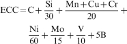
The equivalent carbon content (ECC) can be used to assess the weldability of steels. A higher ECC indicates that the steel is difficult to weld. The numerical value of the ECC is a function of the carbon content and the various alloying elements, as shown in the following equation22
Current rail welding techniques, such as thermite and flash butt welding, are very expensive and time consuming.23– 25 The development and evaluation of alternative repairs have great economical importance, as well as great technical challenges. Slot welding, using multipass gas metal arc welding (GMAW), is a promising method that could address these issues. Before repairs, service induced defects in the railhead, away from any rail joining welds, are accurately mapped and removed via machining. The welding process uses multipass GMAW to fill the slots with filler material. Any excess weld material is then ground to conform to the contour of the rail.
Studies have shown that rail welds are significant sites for the development of fatigue defects because they are usually less superior to the rails they join.26– 29 Inclusions, porosity, lack of fusion or other types of defects that may be present in the welded rail are the main crack initiation sites for weld fatigue failures. These defects may be small but are located where fatigue cracks may initiate, propagate and lead to rail failure. Investigations by Lawrence et al. showed that there was a higher frequency of railhead fatigue defects than rail fatigue defects present in the web and base of the rail.30 Fatigue tests conducted on welded rails illustrated that its crack growth behaviour was very different from the rail steel in that the crack growth rate was unstable and exhibits a series of growth rate plateau. It was also observed that there were occurrences of secondary cracks some distance away from the primary crack front in the welded metal's microstructure.27
There is a limited amount of data on the bending fatigue characteristics of rail steels and an even lesser amount on rail steel welds. This makes it difficult to assess and analyse the fatigue and fracture characteristics of rail steels and their corresponding rail welds. It is therefore imperative to study the fatigue behaviour of rails when they are welded in order to prevent accidents due to fatigue fracture of welds and to lower the cost for rail maintenance.
In this work, slots were placed in J6 bainitic rail steels to simulate defect removal from the railhead. The GMAW was used to weld the slots until they were completely filled. Fatigue crack propagation (FCP) tests were performed on the parent and slot welded bainitic steels by employing the single edge crack three-point bend specimen. This test was chosen because bending stresses associated with wheel passage are responsible for crack propagation in rails.31, 32 The three-point bend FCP will simulate the cracks moving in the transverse direction of the railhead. This is crucial since most cracks in rails originate in the railhead and usually propagate in the transverse direction due primarily to bending.30, 31
Materials and experimental
Materials
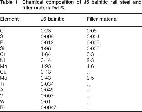
The parent material used was the J6 bainitic rail steel, which had similar size to a typical railhead. They had a thickness of 30 mm, width of 75 mm and length of 100 mm. The filler material that was used is a commercially available low alloy GMAW wire. This wire was selected based on having the closest tensile strength when compared to the parent material. The chemical composition of the rail steel and filler material used is shown in Table 1. The gas mixture used to shield the weld puddle was 98%Ar and 2%O.
Chemical composition of J6 bainitic rail steel and filler material/wt-%
Experimental
A slot was milled at the centre of the rail specimen having a width of 25·4 mm and a depth of 12·7 mm. This was performed to simulate the removal of service defects from the railhead. The rail steel was heated to a temperature of 150°C before welding. This preheat temperature was found to be the optimum for the current specimen geometry and material composition. The slot was then welded using multipass GMAW until the slot was completely filled. A heat input of 1400 kJ m−1 and a wire feed speed of 10·41 m min−1 were employed.
After welding, the specimens were machined from the welded rail section with the weld at the centre of the specimen and were ∼70 mm long, 13 mm wide and 6·5 mm thick. A 90° notch was machined at a free edge in the centre of the specimen, placing the notch at the centre of the weld. The notch depth was ∼3 mm. The span S was 50 mm. The specimen geometry and the loading configuration are shown in Fig. 1 with shear and bending diagrams.
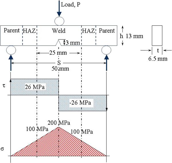
Test specimen showing dimensions, loading configuration and shear and bending stress diagrams
The metallurgical features of the parent bainitic steel and the corresponding heat affected zone (HAZ) and weld material after welding were studied using the Olympus GX51 metallurgical microscope. The microscope is equipped with the PAXcam5 digital camera. The camera is connected to a computer running the PAX-it 7·2 software, which is used for image capturing and analysis. The grain size number was calculated using an analysis tool provided with the PAX-it software, which is based on the intercept method outlined in ASTM E112.
The FCP tests were performed at room temperature under load control conditions using a sinusoidal waveform. A frequency of 1 Hz was used with maximum stress of 200 MPa and minimum to maximum stress ratio of 0·1. A video camera was used to capture the damage associated with crack growth and to measure the crack length. Three samples were tested from each material, and typical samples were used for FCP analysis and fracture surface examinations.
Results and discussion
Flexural properties
Three-point bend tests were performed on the parent and welded bainitic rail steels. The average flexural stress versus load point displacement of the parent and slot welded bainitic steels are shown in Fig. 2. The average ultimate and flexural yield strengths are higher for the parent bainitic rail steel when compared to the slot welded bainitic steel. The average ultimate flexure strengths of the parent and welded bainitic steel are 2600 and 1950 MPa, respectively. This implies that the flexural weld efficiency is 75%. The flexural weld efficiency is the ratio of the flexural strength of the weld to the flexural strength of the parent material.
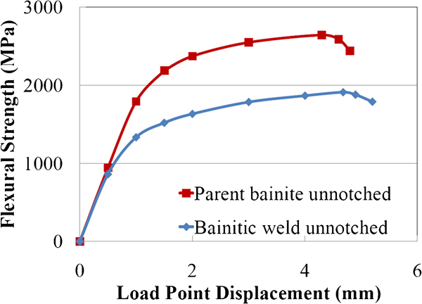
Flexural stress versus load point displacement of unnotched parent and welded bainitic steels
There is a 27% decrease in the average flexural yield strength of the slot welded bainitic rail steel when compared to the parent bainitic steel. The slot welded bainitic rail steel had an average flexural yield strength of 1500 MPa, while the parent bainitic steel had an average value of 2100 MPa.
Microstructural analysis
The parent bainitic steel is characterised by non-lamellar ferrite with interlath particles of retained austenite (Fig. 3a). The grain size number of the parent bainitic steel was found to be 3·91. The grain boundaries are very thin and easy to see. The average hardness of the parent bainitic steel was 425 HB. The HAZ of the welded bainitic steel sample is shown in Fig. 3b. It shows much thicker grain boundaries and relatively smaller grains. The grain size number was computed, and a value of 6·65 was obtained. The average hardness observed in the HAZ was 405 HB.
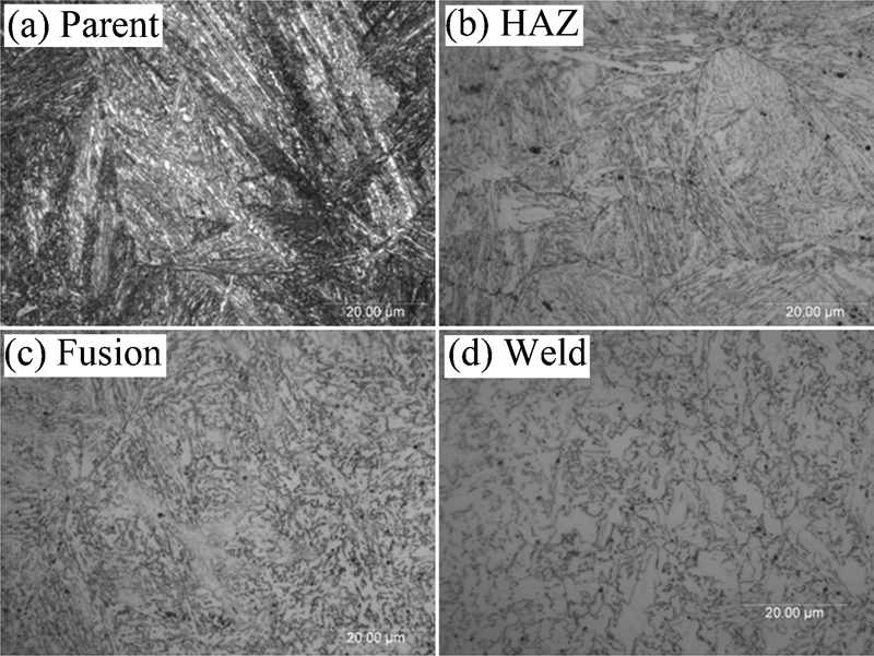
Bainitic micrographs at ×100 magnification showing images captured at different locations on welded bainitic specimen
The fusion zone was closely monitored for crack initiation during testing. Extensive microstructural analyses along the width and depth of the fusion zone of the tested samples were also performed. This was performed because the fusion zone is typically a weak point in welds caused mainly by improper fusion. Figure 1 shows the shear and bending diagram when the maximum stress of 200 MPa is applied during fatigue testing. The diagram illustrates that, at the maximum stress during fatigue testing, the bend and shear stresses applied to the fusion region were 100 and 26 MPa respectively. These stresses are high enough that if any microscopic defects are present at the fusion region, the defects would propagate. The fusion region is shown in Fig. 3c with the HAZ on the left and the weld on the right. The optical examinations were performed on polished etched and unetched samples taken from different locations in the weld. There were no defects noticed at the fusion region, which indicates that there was a good fusion between the bainitic rail steel and the weldment and that the welded joint maintained its integrity at the fusion region during testing.
The microstructure of the welded bainitic steel (Fig. 3d) shows that the welded area consists mainly of ferrite. Small amounts of pearlite were also observed when scanning electron microscopy was used. The grain size number was found to be 12·18. The welded region had an average hardness of 325 HB, which is ∼24% decrease when compared to the parent bainitic steel.
Fatigue lifetime and crack speed
The durability of the slot welded J6 bainitic rail steel was assessed using FCP experiments, which were performed on three-point bend specimens. The crack length at intervals of the number of cycles was recorded during fatigue tests. The average crack length a versus number of cycles N for the parent and slot welded bainitic rail steel is shown in Fig. 4. The total fatigue lifetime of the welded bainitic steel was slightly higher than the parent steel. The total average fatigue lifetime of the parent bainitic steel was ∼36 000 cycles, while the slot welded bainitic steel was ∼39 000 cycles. The critical crack lengths of the parent and welded bainitic steels were 7·25 and 7·75 mm, respectively.
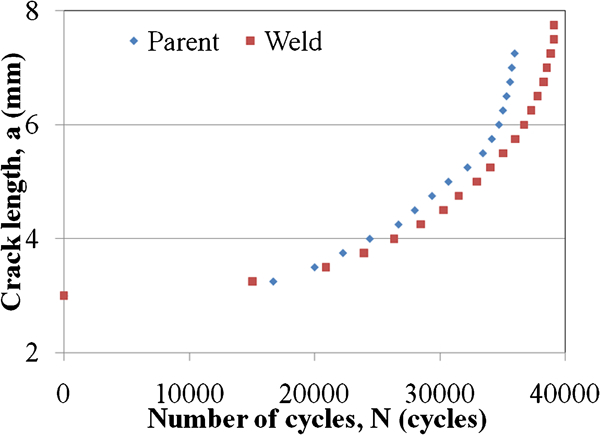
Fatigue crack length a versus number of cycles N
The slope of the curves in Fig. 4 was calculated at various intervals of crack length and is taken as the average crack speed. The relationship between the average crack growth rate, da/dN, and the crack length, a, of both parent and welded bainitic steels is shown in Fig. 5. Both curves display a sigmoidal crack growth behaviour, which can be divided into three stages. The first stage is the crack initiation, which extends from the beginning of the crack length to ∼3·75 mm. In the second stage, stable crack propagation was observed. Unstable crack propagation was observed in the third stage. Over the three stages, the crack growth rate was similar for both steels at the same crack length.
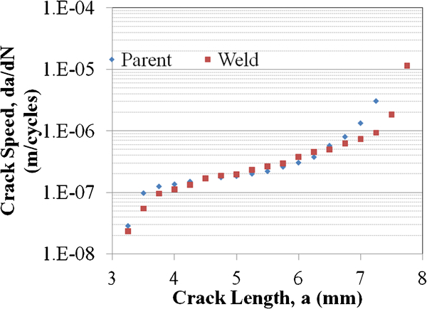
Crack speed da/dN versus crack length a
Fatigue crack propagation kinetics
The hysteresis loops were recorded at intervals of the number of cycles corresponding to specific crack lengths. The potential energy P was calculated by taking the area above the unloading curve. The relationship between the potential energy and the crack length was determined. This relationship was then used to calculate the energy release rate, J*, based on the following equation

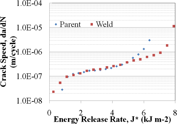
Crack speed da/dN versus energy release rate J*
The deceleration of the crack for both parent and welded bainitic steels started after an energy release rate above 2 kJ m−2. In the second stage, the FCP kinetics was similar for the parent and slot welded bainitic rail steels. However, over the entire stable crack propagation stage, the welded bainitic steel dissipates more energy than the parent steel, which takes more energy from the fracture process and therefore reduces the crack growth rate.
Fracture surface morphology
The crack propagation direction of all the fracture surfaces is from left to right and is taken at ×1000 magnification. The fracture surface morphology of the fatigue tested parent bainitic sample is shown in Fig. 7. This image was taken at the beginning of the stable crack propagation region and shows extensive fatigue damage on the fracture surface. This is manifested by ductile intergranular tearing features and extensive ridge formation. These features are indicative of a crack deceleration process and signify a very high energy consuming process.13, 20
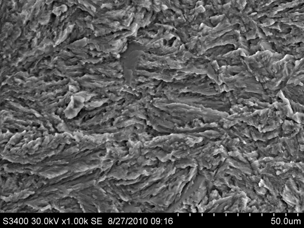
Image (SEM) of parent bainitic at ×1000 magnification taken from beginning of stable crack propagation region
The fracture surface morphology of the welded bainitic rail steel at the beginning of the stable crack propagation region was examined and is shown in Fig. 8. Pulled up materials and tearing ridgelines are observed in this region. The tearing ridgelines are aligned along the crack direction. These features are associated with ductile fracture.
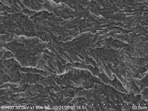
Image (SEM) of welded bainitic steel at ×1000 magnification taken from beginning of stable crack propagation region
The fracture surface at the middle of the fast crack propagation region of the parent bainitic steel is shown in Fig. 9. The fracture surface contains void coalescence at multiple locations, which is indicative of high resistance to material separation. Tearing ridges and limited microcracks are also noticeable on the surface. The fracture surface morphology over the entire fractured surface of the parent bainitic steel reveals a ductile failure mechanism.
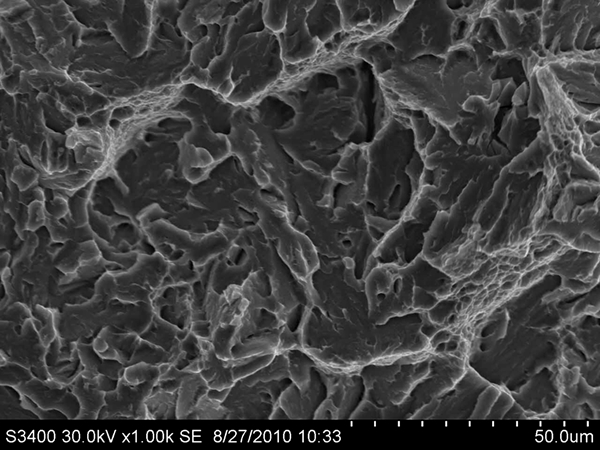
Image (SEM) of parent bainitic at ×1000 magnification taken from middle of fast crack propagation region
The micrograph taken at the middle of the fast crack propagation region of the welded bainitic steel is shown in Fig. 10. Microvoid coalescence is observed, which is associated with ductile failure. Therefore, for the welded bainitic steel, the entire fracture surface displays a ductile failure mechanism.
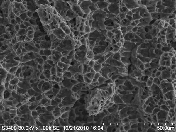
Image (SEM) of parent bainitic at ×1000 magnification taken from middle of fast crack propagation region
The fatigue fracture surface morphological features revealed that the parent and slot welded bainitic steels consist of mostly a ductile fracture mechanism over all three FCP stages.
Conclusions
Slot welding of J6 bainitic rail steels was successfully performed. Based on testing and data analyses of the parent and slot welded bainitic steels, the following conclusions are drawn.
The flexural weld efficiency was found to be 75%. The parent bainitic rail steel had an average flexural yield strength of 2100 MPa compared to 1500 MPa for the slot welded bainitic rail steel.
Microstructural examinations revealed that the welded area consisted of mainly ferrite. The HAZ had thicker grain boundaries and smaller grains when compared to the parent bainitic steel.
Fatigue tests showed that the fatigue lifetime and FCP kinetics were similar for the parent and slot welded bainitic steel, indicating similar resistance to FCP.
The fatigue fracture surface morphology of the parent and welded bainitic rail steel both revealed mostly ductile fracture mechanism.
Footnotes
Acknowledgements
This work was sponsored by the Federal Railroad Administration (FRA). The authors would like to acknowledge Mr J. Stringer for assisting in the sample preparation of the bainitic rail steels.