
Abstract
The metal transfer process of gas metal arc welding with strip electrode is observed by a high speed digital camera system. Because the rectangular strip electrode has a large width/thickness ratio, the pendant droplet is elliptical in shape, and multicurrent channels are generated. The Lorentz force induced between the multicurrent channels drives the droplet and welding arc to move along the strip electrode end, but the droplet always lags behind the welding arc. The movement results in uncertain droplet's detaching location and transition trajectory. The projected transfer mode is promoted, and the streaming and rotating transfer modes are restrained. With the increase in welding power, the droplet motion is faster but more stable. The stability can be reflected from the fluctuation of the welding current and arc voltage waveforms.
Introduction
Gas metal arc welding (GMAW) is now widely used in the industry as a high quality welding method. It can be used to weld a variety of metals. Its welding process is stable enough to be monitored and controlled. However, the traditional GMAW with round wire is usually limited to 500 A of welding current and 1 m min−1 of travelling speed respectively in actual production. It is hard to further improve its welding efficiency just by simply increasing the welding current or travelling speed. It can lead to undercut and humping weld defects when welding with large current and high travelling speed.1– 3 To that end, many improved GMAW methods appear, such as tandem GMAW, 4 4,5 T.I.M.E. process, 6 6,7 variable polarity GMAW 8 8,9 and double electrode GMAW. 10 10,11 Recently, another novel variant of GMAW, which is referred to as strip electrode GMAW, was invented and implemented by researchers. 12 12,13 This method works with the strip electrode, which has a rectangular cross-section, instead of the traditional round wire as consumable electrode.
However, since the present reports on this new method are mainly focused on engineering application, studies on its metal transfer mechanisms and arc behaviour are seldom reported. Owing to its particular profile of the strip electrode, it is imperative to figure out the physical process of the metal transfer. This is also useful for better understanding the characters of the new method.
With the development of welding technology, a number of sensing techniques have been developed, e.g. sensing of airborne sound, sensing of welding arc voltage, sensing of arc radiation and high speed imaging. Compared with other methods, high speed imaging can directly record the droplet transfer processes and droplet shapes. In this paper, the metal transfer and welding arc behaviour of GMAW with strip electrode were studied by the high speed digital camera system. The emphasis was placed on the analysis of the metal transfer characteristics and the droplet motion during its detaching.
Experimental
The schematic diagram of the experimental system is shown in Fig. 1. It consists of the welding process system, the metal transfer photographing system and the welding electrical signal acquisition system. The welding process system has been set up on the basis of a self-designed welding torch special for GMAW with strip electrode. The basic welding principle of GMAW with strip electrode is the same as the traditional GMAW with round wire. The main difference is that the strip electrode is flat. In the present study, a flat contact tip is specially designed according to the feature of the strip electrode.
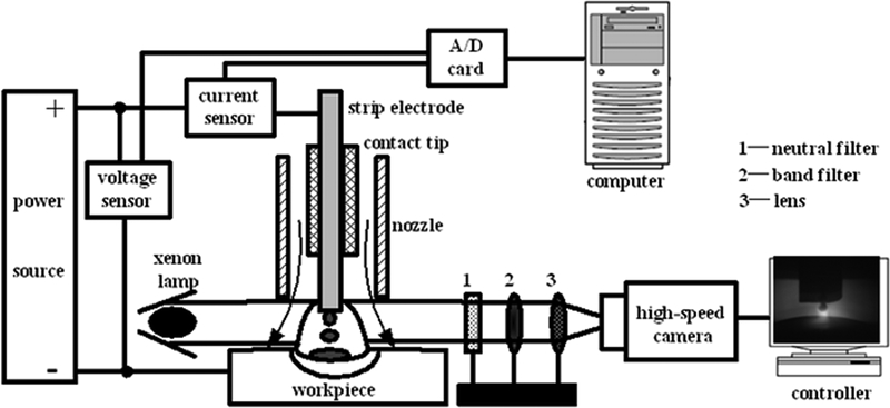
Schematic diagram of experimental arrangement
As it is well known, there is intensive arc light radiation and much fume generating in GMAW. It induces that it is very difficult to observe the metal transfer process. In order to study the metal transfer process, a Dalsa CA-D6 high frame rate digital camera is used to obtain the images of the droplet detaching process in this work. It is operated at a speed of 955 frames/s. A continuous xenon lamp is used as the backlighting source to eliminate the interference of arc light. At the same time, the arc voltage and welding current are measured with Hall sensors. The sampling rate is 15 kHz.
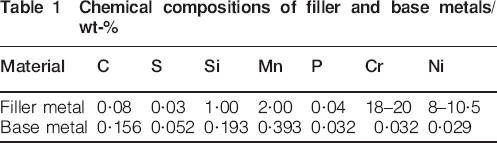
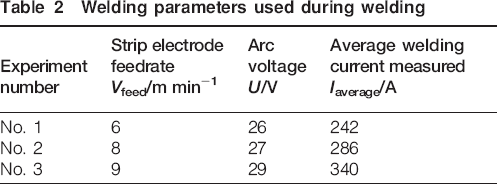
The welding power source is a Kemppi ProMIG 500. It is operating in constant wire feed and constant voltage mode. The filler metal is an SUS 304 stainless strip with 0·2 mm thickness and 6 mm width. Its cross-section area is similar to that of the round wire with 1·2 mm diameter, but its surface area is nearly 3·3 times the size of the round wire. The profiles of the strip electrode and the round wire are compared, as shown in Fig. 2. The base metal is a low carbon steel of Q235 with 6 mm thickness. The chemical compositions of the filler and base metals are shown in Table 1. Ar+5%CO2 with a constant flowrate of 17 L min−1 is used for shielding gas. The contact tip to workpiece distance and the welding speed are kept constant in the experiments, which are 13 mm and 30 cm min−1 respectively. The typical welding parameters are given in Table 2.
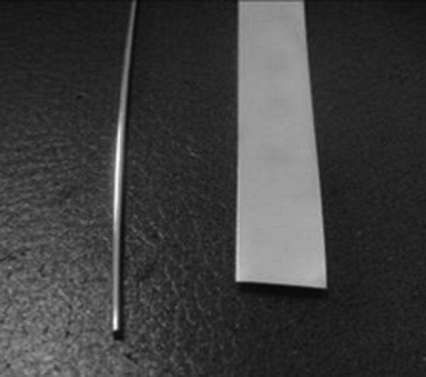
Profile of strip electrode and round wire
Chemical compositions of filler and base metals/wt-%
Welding parameters used during welding
To study the metal transfer characteristics of GMAW with strip electrode, bead on plate welds are made in the flat position by changing the strip feedrate and arc voltage. The high speed images and waveform signals are collected when the welding process is stable after the start of welding.
Results and discussion
Metal transfer process under different welding parameters
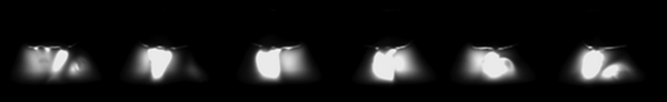
Figure 3 Figure 4 Figures 3–5 show the typical metal transfer processes under the experimental conditions given in Table 2. Each image series in these figures represents at least a complete transfer cycle. It is found that the phenomenon of strip electrode melting and metal transfer process feature each other under different welding parameters.
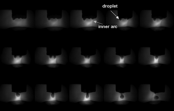
Metal transfer process of experiment no. 1 (interval for 1·05 ms)
Metal transfer process of experiment no. 2 (interval for 1·05 ms)
Metal transfer process of experiment no. 3 (interval for 1·05 ms)
The strip electrode used in this study is as wide as 6 mm. It provides the condition of uneven distribution of welding current along the width. When welding with experiment no. 1, the welding power is relatively on a low level. The whole strip electrode end cannot melt at the same time. The local areas that are nearest to the welding pool melt first. Therefore, it can be seen from the images in Fig. 3 that there are several small droplets generated simultaneously at the end of the strip electrode. Meanwhile, an inner arc as marked in the figure is burning between each small droplet and the welding pool. During the welding process, the inner arcs attract each other and pull together into a coupling arc. Meanwhile, the small droplets move to each other along the strip electrode end and merge into a big one. Then, it grows further and finally detaches by gravity. Through statistical analysis of the images captured, the transfer frequency is as low as 64 Hz, and the droplet is as big as 1·8 mm in diameter. According to the classification of metal transfer in the traditional GMAW with round wire by droplet size and transfer frequency, the droplet here transfers with globular transfer mode. It must be pointed out that only one droplet transfers to the welding pool at a time, although there are several small droplets generated. However, the detachment location at the strip electrode end is random because of the droplet motion.
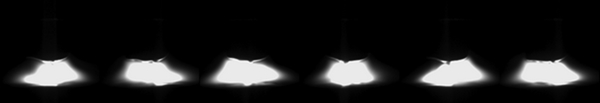
Figure 4 shows the typical strip electrode melting phenomenon and metal transfer process with experiment no. 2. It can be seen that the strip electrode melts almost uniformly, and only one droplet is generated most of the time. Between the droplet and the welding pool, there is almost only one inner arc burning. The droplet sways along the strip electrode end. It grows up by absorbing the molten metal and then detaches. Compared with Fig. 3, the transfer frequency increases to 120 Hz, and the droplet reduces to 1·36 mm in diameter. With reference to the metal transfer characteristics in the traditional GMAW with round wire, the metal transfer process belongs to the projected transfer mode. The major difference is that the droplet flight trajectory in Fig. 4 is not perpendicular to the welding pool, and the detachment location from the electrode end is uncertain.
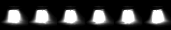
Figure 5 shows the typical strip electrode melting phenomenon and metal transfer process with experiment no. 3. Owing to the large welding power, the strip electrode melts uniformly all the time, and only one droplet with an inner arc of reverse conical shape is generated. During the transfer process, the droplet moves and detaches at the central area of the strip electrode end most of the time. Therefore, a new droplet is formed again at the detachment location of the former detached droplet. It must be noted that the droplet still transfers mainly with projected transfer mode similar to that in Fig. 4, but the transfer frequency is high up to 200 Hz at least, and the detached droplet is smaller than 1·2 mm in diameter. When the welding power is increased further until the output limit of the welding power source, the metal transfer process is similar to that in Fig. 5 but with a higher transfer frequency and a smaller droplet.
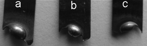
As it is well known, the droplet is considered to be spherical generally in the traditional GMAW with round wire. However, in this new method, the droplet presents different shapes. Because the strip electrode is rectangular and the width/thickness ratio is as large as 30∶1, the pendant droplet is elliptical, which can be verified from the profile of the remaining metal at the strip electrode end in Fig. 6. After it detaches, the shape of the droplet depends on the welding condition. Figure 7 shows the enlarged images of the droplet corresponding to experiment nos. 1–3. With the increase in welding current, the droplet moves faster and transfers at higher frequency with smaller size. It is easier to be deformed by the motion, which can be proved by comparing Figure 3 Figure 4 Figs. 3–5. Considering the surface tension effect, the droplet tends to be spherical as that in Fig. 7a at low current and becomes elliptical as shown in Fig. 7b and c at high current.
Profile of remaining metal
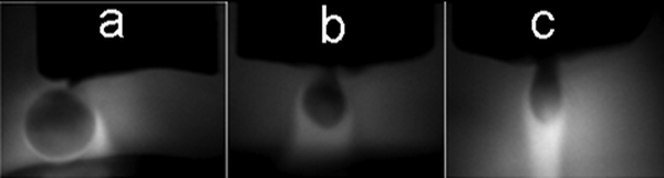
Enlarged image of droplet
When welding with the 1·2 mm diameter stainless steel round wire under the current of experiment no. 3, the droplet has already transferred with streaming or rotating transfer mode. However, it is hard to get steady streaming or rotating transfer mode for >10 ms during the experiments of this new welding method. They can easily change into projected transfer mode after occurring.
There are two typical reasons for this phenomenon. First, when welding with large current in the traditional GMAW with round wire, the wire tip is tapered, and the welding arc is conical in shape, which are the key factors to form the streaming transfer mode. However, the strip electrode is hard to be tapered because of its rectangular cross-section even at high current, which can be seen from Fig. 5. Because of the rectangular strip electrode, the welding arc is not conical, and its cross-section gradient from the anode to cathode is small. It indicates that the plasma flow and the arc pressure are weakened compared with the traditional GMAW with round wire. Therefore, the special strip electrode limits the probability of the formation of streaming transfer mode. Second, in the streaming or rotating transfer mode in the traditional GMAW, the molten metal transfers just like a continuous thin metal stream jetting from the tube-like round wire. In this new method, the strip electrode is much wider than the round wire. Therefore, the molten metal can flow along the strip electrode end to generate a droplet at any location. The droplet has already grown up to detach before the molten metal formed a metal stream. Therefore, the metal stream is hard to occur. Even if the metal stream is formed, it is also driven to move along the strip electrode end, and its continuity and stiffness are destroyed. Then, the metal stream disappears, and the streaming transfer mode is transformed to the projected transfer mode with a high transfer frequency.
Mechanism of droplet movement along strip electrode end
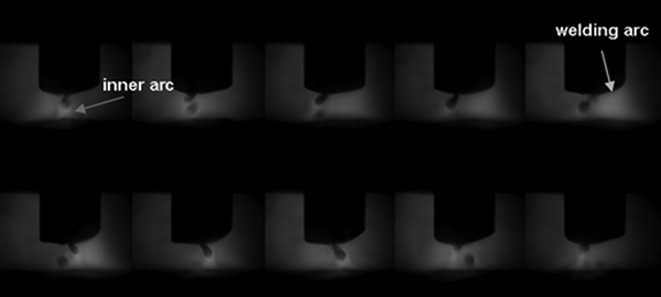
Through the above observation of the metal transfer process under different welding parameters, there is a common phenomenon that the droplet always moves along the strip electrode from its formation to detachment. In order to figure out the mechanism of the movement, the welding arc behaviour corresponding to the welding parameters in Table 2 is captured, as shown in Figure 8 Figure 9 Figs. 8–10.
Arc behaviour with same welding parameters as Fig. 3 (interval for 3·15 ms)
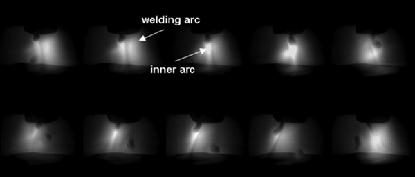
Arc behaviour with same welding parameters as Fig. 4 (interval for 2·1 ms)
Arc behaviour with same welding parameters as Fig. 5 (interval for 1·05 ms)
Figure 8 shows the arc behaviour when welding with the parameters of experiment no. 1. Because of low welding power, several dispersed inner arcs burn at the strip electrode end and divide the major welding current into several parts. They become the main channels of the welding current flowing into the workpiece with the same direction. According to the theory of electromagnetic, Lorentz force is induced. Therefore, the arcs attract each other, as shown in the first eight images in Fig. 3, and finally become a coupling arc in the ninth image. At the same time, the small droplets move along the end of the electrode and then merge into a big one. From Figure 3 Figs. 3 and 8, it can also be seen that the lower part of the inner arcs has already attracted each other, while the upper part attaching on the droplets is still apart from each other. That is to say, the small droplets are droved to move on the electrode end by the inner arcs.
With the increase in the welding power, a complete welding arc is burning at the electrode end, as shown in Fig. 9. It can be seen that the welding arc moves along the strip electrode left and right repeatedly. When checking the droplet motion in Fig. 4, it sways along the strip electrode. The frequency is nearly the same as that of the moving welding arc. However, the droplet is always lagging behind the welding arc by careful analysis. Especially, in Fig. 4, it can be distinguished that the welding arc already transfers to the right of the strip electrode in the fifth image, but the droplet is still deflected to the left. Until the sixth image, it is just driven to the right. This phenomenon is common in the experiment. Therefore, it can be concluded that the moving welding arc induces droplet swinging.
This can be explained from the force strategy. As it is well known, the plasma of the GMAW arc can be divided into two parts. One part mainly consisted of ionised shielding gas, and the other mainly consisted of ionised metal particles. The former is called welding arc, and the latter is called inner arc in this paper. In this new GMAW method, the welding arc, which burns between the electrode end and the welding pool, is elliptical because of the special strip electrode. However, the inner arc, which burns between the droplet and the welding pool, nearly has a cylindrical symmetry. They compose two channels that separate the welding current into two portions with different proportions. Owing to the many uncertain factors during welding, they are not usually co-axial. Therefore, the Lorentz force is formed between them and pulls them together. The droplet has inertia because of its weight, and the welding arc does not have inertia because of its flexibility. Therefore, the welding arc can move freely along the strip electrode end but the droplet cannot. As a result, the droplet can only chase after the moving welding arc.
As to the condition in Fig. 5, the droplet also follows the welding arc to move along the strip electrode end, which is similar to that in Fig. 4. However, the time that the droplet lags behind the welding arc is much smaller. This is because the Lorentz force and the plasma flow are both strengthened, and the detached droplet is much smaller. The welding arc does not move violently but burns steadily, as shown in Fig. 10. Therefore, the small droplet can rapidly follow up the moving welding arc.
Based on the above analysis, there are two kinds of movement mechanisms under variable welding power, which can be concluded as follows.
Multidroplets
Figure 11a shows the schematic diagram of the movement with multidroplets (e.g. two droplets). I1 is the current that flows though the left droplet and its attached arc. I2 is the current that flows though the right droplet and its attached arc. The direction of I1 and I2 is almost the same. Therefore, Lorentz force F is generated. In this multidroplet mechanism, the total welding current is usually on a low level and is divided into several parts, so the current flowing into every small droplet and its attached inner arc is much lower. This results in two effects on the droplet. On the one hand, the effect of electromagnetic pinch and plasma flow on the small droplet is very small. As a result, there is no droplet transfer before the small droplets merge into the big one. On the other hand, it can be seen from Fig. 3 that the inner arc is much darker than the coupling arc. It indicates that the temperature of the inner arc is very low. This results in less superheating of the droplet and less metal evaporation. As to the Lorentz force F, it makes the small droplets move along the strip electrode and drives them to merge into a big one. However, the value of the force is small, and the moving speed is slow. Therefore, the Lorentz force F has a limited effect on the droplet transfer directly.
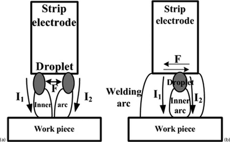
Mechanism of droplet movement
Single droplet
Figure 11b shows the schematic diagram of the movement with a single droplet. I1 is the current that flows though the welding arc. I2 is the current that flows though the droplet and its attached inner arc. Because the welding arc and the inner arc are not usually co-axial, Lorentz force F is generated between I1 and I2. Compared with the multidroplet mechanism above, the welding current is on a high level in the single droplet mechanism. The Lorentz force F is strong, and it drives the droplet to move along the strip electrode fast. As a result, the droplet has an apparent bending deformation, as shown in Figure 4 Figs. 4 and 5, which influences the metal transfer mode, as analysed previously. Therefore, the Lorentz force F has a great effect on the droplet transfer.
Effect of motion on welding process
The motion of the droplet and arc has a great effect on the welding process. It can be revealed from the waveforms of welding current and arc voltage, as shown in Fig. 12. From the waveforms, it can be seen that the variation of the welding current and especially the arc voltage has a certain periodicity. The cycle nearly agrees with the metal transfer frequency, as observed in Figure 3 Figure 4 Figs. 3–5. It can also be seen that the time between every two cycles is dynamic, and the waveforms are distorted at times. This is induced by the droplet and arc motion, which change the regularity of metal transfer. However, the cycle of the waveforms is statistically stable during the welding process. Therefore, the waveforms should contain the information of droplet transfer and its motion. It should be noted that the fluctuation of the welding current, such as in Fig. 12c, is caused mainly by the inverter welding power source and not by the droplet movement.
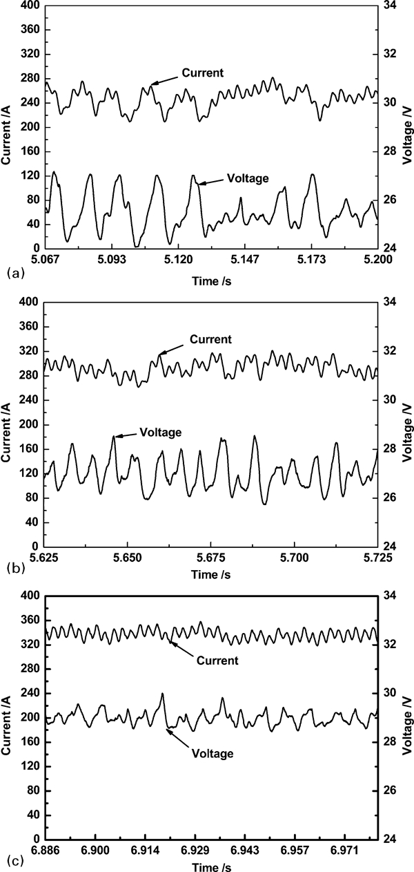
Arc voltage and welding current waveforms in experiments
Comparing the fluctuation of the electrical signals in Fig. 12, the arc voltage deviates by ∼4, 2 and 1 V from the minimum to the maximum respectively, and the welding current deviates by ∼60, 40 and 20 A respectively. It indicates that the stability of the movement is enhanced with the increase in welding power. This can be proved from the change of the arc behaviour in Figure 8 Figure 9 Figs. 8–10. When the welding power is low, the dispersive multiarcs move violently, which makes the droplet move along the whole strip electrode end with an extensive space usually. The small plasma flow and arc pressure cannot restrict the movement of big droplets. Then, unstable droplet transfer results, and metal spatter occurs. With the increase in welding power, the concentrated welding arc moves gently, and the plasma flow and arc pressure are both strengthened. Although the moving speed is fast, the droplet can be restricted to move at the central area of the strip electrode end. Therefore, the welding process is much more stable.
Conclusions
The metal transfer process of GMAW with strip electrode is studied. The pendant droplet is elliptical, and it moves along the strip electrode end from generation to detachment.
Owing to the movement, the droplet's detaching location and transition trajectory between the electrode and the welding pool are not certain. The projected transfer mode is promoted, and the streaming and rotating transfer modes are restrained.
The Lorentz force induced between the multicurrent channels makes the droplet move after the welding arc. With the increase in welding power, the movement is faster but more stable. The stability can be reflected from the fluctuation of the welding current and arc voltage waveforms.