
Abstract
The interfacial characteristics of the SiC/glass solder/SiC joining part were investigated by means of thermodynamic and wetting behaviour calculation, microstructure observation, chemical structure and element analysis. The results of wavelength dispersive spectroscopy linear scan across the joint showed a relatively low increase in sodium content at the interfaces, which indicated that the sodium silicates in glass could react with silicon carbide substrate at the joining temperature, but it is not the reason for the good bonding between SiC and the interlayer. The mechanism of the good interfacial bonding lies in the formation of oxycarbide phase at the interface.
Introduction
Since the last century, silicon carbide has been extensively studied and widely used in aerospace, semiconductor, automotive and nuclear industries, etc. because of its excellent mechanical properties, good resistance to thermal shock and corrosion, high thermal conductivity, good optical performance and low density. 1 1,2 In many of these practical applications, articles with large sizes and/or complicated shapes are often required. However, due to the poor machinability of silicon carbide ceramics and high cost of processing, the joining of relatively small parts together is an alternative route. Up to now, various joining techniques have been developed, such as brazing, diffusion bonding, soldering and reaction bonding.3– 9
As we know, the interfacial characteristics at the joint play a very important role in the properties of joining parts including the intrinsic strength and fracture behaviour.
10
10,11 In consideration of the application, an ideal joint should have a well bonded and stress free interface. The joining of SiC with glass solder has been studied in the literature. Nevertheless, there is quite a little report available on interfacial interaction between molten glasses and silicon carbide, especially in air atmosphere.12–
14 In order to decide whether the reaction would take place during joining, it is important to figure out the possibility of interactions between the individual constituent of glass and silicon carbide. Yurkov and Polyak reported that silicon carbide would not react with Na2O, K2O, BaO, CaO, MgO, Al2O3 and Y2O3 up to 1400°C.12 At the same time, they pointed out that the presence of sodium and potassium cations in the melt would enhance the interaction with silicon carbide.12 Because there exist a couple of forms of alkaline silicates, such as Na2Si3O7, Na2Si2O5 and Na2SiO3, the reaction between silicon carbide and silicates can be expressed as follows15

As shown in equation (1), a gaseous phase would be formed after reaction, which may accelerate the reaction towards the right direction.
In our previous studies, as sintered silicon carbides were joined with Na2O–B2O3–SiO2 glass solder and the four point bending strength of the jointed specimens was as high as 218±23 MPa at room temperature and 154±35 MPa at 400°C. The aim of this work is to study the probable reactions at the interface during the joining process and to explain the possible mechanism of bonding correspondingly.
Experimental
Materials preparation
The silicon carbide specimens were prepared by pressureless sintering at 2200°C in Ar atmosphere with 3–5 wt-%C and 1–3 wt-%B4C as sintering aids. The density of sintered SiC specimens is 3·12 g cm–3, and the average flexural strength at room temperature is over 400 MPa.
The Na2O3–B2O3–SiO2 glass used in this investigation was obtained by melting the mixture of Na2CO3, H3BO3 and SiO2 powder at the molar ratio of 3∶44∶53 (previous experiment showed that the coefficient of thermal expansion of glass with this composition is close to that of SiC substrate below temperature of 400°C) in a Pt crucible at 1350°C for 2 h in an electric furnace followed by quenching on a stainless steel plate. The glass was then ground into powder with particle size below 10 μm for the subsequent use as the joining solder.
Before joining, SiC specimens were ground into a rectangular shape with size of 18×20×20 mm and then cleaned ultrasonically in deionised water and in acetone. Then, the solder was dispersed in ethanol to form slurries with the solid content at ∼70 wt-%. In addition, 1 wt-% (relative to solid) of polyvinyl butyral was added as the binder. After homogenising, the slurry was applied onto the joining surface by tape casting method. The thickness of the interlayer was controlled by the gap height of the doctor blade. After coating with solder, the joining surfaces were mated together to form a sandwich structure, and a pressure of ∼133 Pa was applied to the specimen to ensure good contact during the joining procedure. Joining was conducted in an electric resistance furnace (TW-4; Zufa Industry Co. Ltd) at a temperature of 1150°C for 10 min. Then, the jointed specimens were cut and ground to the required dimension for measurements.
Characterisation of interface
In order to investigate the possible reaction between SiC and glass phase, a SiC–glass powder mixture was prepared and heat treated in furnace. A defined amount of silicon carbide ceramic was ground into powder (grain size, <200 mesh) and mixed with the solder powder in a mass ratio of 1∶5 to be sure that both phases have good surface contact. The mixture was applied onto a silicon carbide ceramic substrate surface and heat treated with the same procedure as joining process, but the holding time at joining temperature was extended to 5 h. After heat treatment, the SiC–glass specimen was ground into fine powder and mixed with KBr powder to make discs for analysis using Fourier transform infrared spectroscopy (FTIR) (7199-CFT-IR, Nicolet, Madison, WI, USA). The IR spectra were measured at room temperature in the wavenumber range of 200–4000 cm−1. Microstructure of the samples was also observed using SEM (JSM-6700F; JEOL, Tokyo, Japan).
Moreover, the microstructure at the interface and the bonding state was measured by electron probe microanalyser (EPMA) (JXA-8100; Japan) equipped with a wavelength dispersive spectroscopy (WDS). X-ray photoelectron spectroscopy (XPS) (ESCALAB850; Thermo Fisher Scientific Inc., UK) was also used to measure the vitrified bonds at the interface between silicon carbide and the solder.
Results and discussion
Microstructure at joint interface between silicon carbide and interlayer
Figure 1 presents the EPMA observation of the joint and WDS linear scan across the SiC/interlayer/SiC specimen. The fact that no cracks or bubbles were observed at the interface indicates that the interlayer is well bonded to the SiC substrate (Fig. 1a). In addition, the interface between the glass and the SiC substrate is quite clear, and there is no obvious transition layers, indicating that there were no or not very serious reaction during the joining process at EPMA scale.
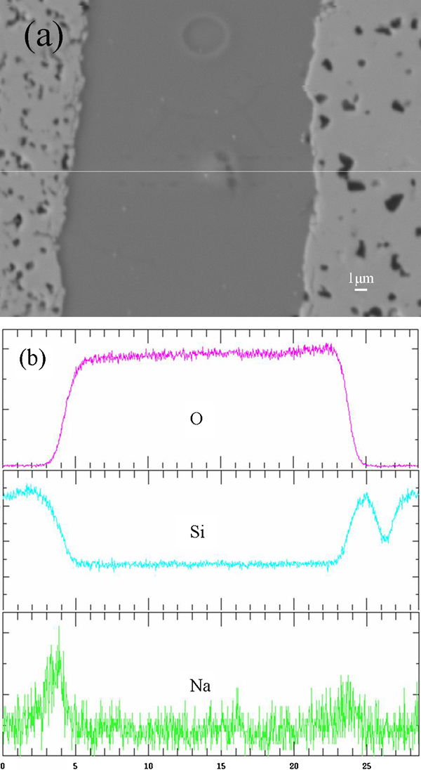
a microstructure at joint and b WDS linear scan across joint
The element distribution of O, Si and Na was characterised through WDS linear scan. It is shown that the O content is higher in the interlayer, while the Si content is lower than that in the substrate respectively. The low concentration of Si in the SiC substrate shown in Fig. 1b is because of the shielding of C (see Fig. 1a). At the interface, the width of transition layers shown in the element concentration profiles is about 2–3 μm, indicating the diffusion of elements at the interface. In previous energy dispersive spectroscopy testing, we have also proved the diffusion of carbon into the glass phase.
Additionally, it was found that there were two sodium peaks at the interface, suggesting the higher concentration of sodium at the respective sites. The enrichment of sodium at the SiC/interlayer interface may be caused by the reaction between the oxide constituent in solder and the SiC substrate.
As mentioned in the section on ‘Introduction’ (equation (1)), the reaction between sodium silicates and SiC would occur at the joining temperature, resulting in the increase in sodium content. For example, after the reaction takes place towards the right direction, the composition of sodium silicate changed from Na2Si3O7 to Na2Si2O5, accompanied by the formation of gaseous products, and the sodium content in the sodium silicate increased from 19 to 23% correspondingly, so that the sodium content at the interface is a little higher than that in the interlayer.
The interfacial bonding can also be characterised based on the wetting Wsl test. The works of adhesion of glass solder on SiC substrate at 1000 and 1150°C were calculated to be 0·38 and 0·4 J m–2 respectively in the previous work. The molar work of adhesion W
μ
was defined to be16


Then, the molar work of adhesion can be calculated as 18·4 and 19·9 kJ mol–1 at 1000 and 1150°C respectively. According to the literature, 16 16,17 the energy of non-reactive wetting is about a few kilojoules per mole, while the value is of the order of hundreds of kilojoules per mole for reactive wetting. Therefore, it is presumed that in this system, the adhesion between SiC and interlay is not mainly the reactive wetting.
Analysis of interfacial bonding between silicon carbide and solder by FTIR and XPS
After heat treatment at 1150°C for 5 h, the ground silicon carbide and glass powder mixture were bonded together and appeared black in colour. This is due to the diffusion of carbon from the dissolved silicon carbide powder to glass. Fourier transform infrared spectroscopy analyses of silicon carbide, glass and the mixture of SiC–glass sintered at 1150°C for 5 h are shown in Fig. 2.
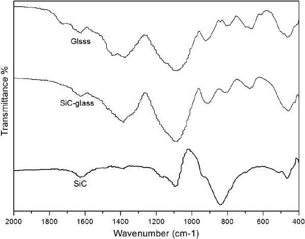
Infrared spectra of glass, heat treated (1150°C, 5 h) SiC–glass and SiC
The band at ∼460 cm−1 can be referred to the bending vibration of Si–O–Si linkages in [SiO4] units. 18 18,19 The infrared spectral range of 900–950 cm−1 is typical for the stretching vibration of [BO4] tetrahedron. 20 20,21 The bond at ∼839 cm−1 represents the stretching vibration of Si–C.22 The band at ∼1090 cm−1 can be ascribed to the symmetric tensile vibrations of Si–O–Si and also the tensile vibration of Si–O–B.23 The bonds at ∼660 and 672 cm−1 in the glass and SiC–glass mixture could be attributed to the bending vibrations of bridging oxygen between trigonal boron atoms.24 In addition, the band at ∼1402 and 1627 cm−1 can correspond to the vibrations of carbonate group and molecular water respectively.19
In comparison of the IR spectra of glass with that of heat treated SiC–glass, it can be found out that all the spectra are similar in the whole wavenumber range except for two differences. The first one is the peak at ∼922 cm−1 for glass while the corresponding one for heat treated SiC–glass shifts to 909 cm−1. The reason for this may be that, after heat treatment, the carbon atoms diffused into the [BO4] structure in glass and replaced some oxygen atoms to form the [B(O4−x,Cx)] structure. Because the electronegativity of carbon atom is lower than that of oxygen atom, when O was partially substituted by carbon atoms, the polarisability of B–O became stronger and the absorption peak transferred to shorter wavenumbers in comparison with the same spectra of glass.25 The second one is the peak at ∼801 cm−1 for glass, which is related to symmetric stretching vibrations of Si–O bonds.19 After sintering at 1150°C for 5 h, the band in the SiC–glass system shifted to 812 cm−1; this may be due to the overlapping of Si–O band in glass and the stretching vibration band of Si–C in silicon carbide at ∼839 cm−1. Moreover, the appearance of Si–O–Si bond or Si–O band in silicon carbide is assigned to the easily oxidative nature of it even at room temperature.
Figure 3 Figures 3 and 4 illustrate the XPS results of wide scan, C1s and Si2p peaks in the glass interlayer and at the contact zone between the SiC and glass respectively. The wide scan in Fig. 3a showed that besides the original elements Na, B, Si and O, there was also a small amount of C. To explain the presence of C in glass, the individual C1s spectrum was deconvoluted into Gaussian bands (see in Fig. 3b).
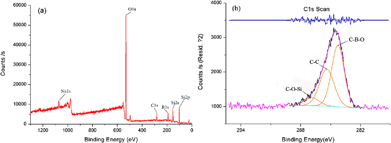
Spectra (XPS) of a wide scan peak and b C1s photoelectron peaks in glass
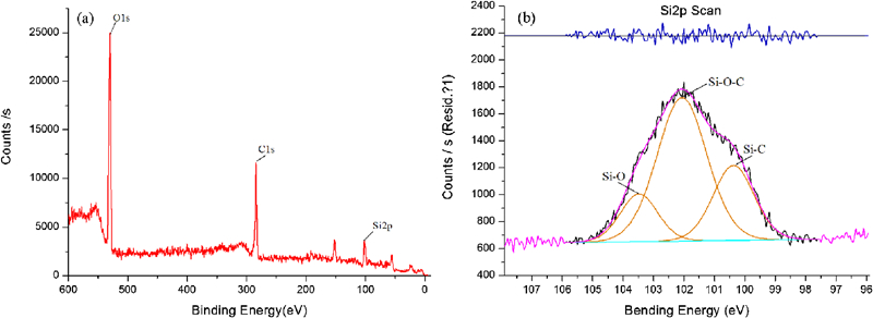
Spectra (XPS) of a wide scan peak and b Si2p photoelectron peaks at contact zone of SiC and glass
In Fig. 3b, the fitted C1s spectrum exhibits three peaks at the binding energies of 284·2, 285·4 and 286·9 eV respectively. The binding energy of 286·9 eV is attributed to C–O–Si bonds26 and that of 285·4 eV derives from the C–C bonds. In addition, the binding energy peak at 284·2 eV may correspond to C–B bonds. The binding energy peaks of C–O–Si and C–B–O illustrated that C atoms diffused into [BO4] and [SiO4] structure in glass, which is proved by the FTIR results.
Meanwhile, the Si2p spectrum at the contact zone of SiC and glass interlayer could be deconvoluted into three peaks at 100·4, 102·1 and 103·5 eV, which were Si–C, Si–O–C and Si–O bonds respectively (Fig. 4b). 27 27,28 The formation of Si–O–C bonds might be due to the dissolution of silicon carbide in glass and the formation of oxycarbide phase at the contact zone between SiC and glass interlayer.13 However, the chemical bonding of the oxycarbide phase at the interface cannot be detected by FTIR, which means that the reaction at the interface is not very serious.
Conclusions
The mechanism of interfacial bonding between Na2O–B2O3–SiO2 solder and silicon carbide substrate has been investigated based on thermodynamic calculation, surface observation, energy dispersive spectroscopy, FTIR and XPS characterisations.
It shows that the sodium silicates in glass can react with silicon carbide substrate during joining. However, the molar works of adhesion of the Na2O–B2O3–SiO2 glass on the SiC substance at the temperature range of 1000–1150°C are only ∼20 kJ, indicating that the adhesion between SiC and interlay is not mainly the reactive wetting. The results of FTIR and XPS also showed that the reaction at the interface is weak and does not play the most important role in bonding.
The XPS and FTIR results showed that during the joining process, SiC may be slightly dissolved into the glass melt, while the carbon atoms from SiC may be incorporated into glass structure to form the oxycarbide phase at the contact zone between SiC and glass interlayer.
Therefore, it is concluded that the mechanism of the good bonding of SiC by glass solder is mainly attributed to the formation of oxycarbide phase at the interface.