
Abstract
The forming behaviour of tailor welded blanks (TWBs) has been widely studied since its development. In the numerical simulation studies, the TWBs are modelled as blanks composed of two different materials, and often, the presence of the weld bead is neglected in its finite element discretisation. In the present work, the influence of the weld bead shape on the formability of friction stir welded TWBs, is analysed. Several finite element meshes were constructed in order to represent different weld bead geometries and numerical simulations of the cylindrical cup drawing were performed. Strong influence of the weld bead shape on the formability of the TWBs was observed when the weld was in overmatch relatively to the base material, and little influence when the weld was in undermatch condition. Comparison of the numerical results with experimental ones shows that the numerical analysis is able to preview the formability of the TWBs.
Introduction
In the automotive industry, an innovative method to produce strong and light panels for the body-in-white structure is tailor welded blank (TWB) technology. The concept of TWB technology is producing panels composed of several sheet metal blanks, that may be of different material grades, strengths, gauge thickness or coatings, which are welded together before the forming process. The joining processes can induce significant differences between the material properties of the weld and the base materials. Hence it is important to investigate whether the weld bead has significant influence on the overall forming behaviour of the welded blanks.
In the present paper, the influence of weld bead geometry on defect formation during deep drawing of aluminium TWBs produced using friction stir welding (FSW) is investigated. As described in several review papers,1– 4 in the FSW process, the tools are mainly constituted by a small diameter entry probe and a concentric larger diameter shoulder, both usually made of high strength steel. During the welding process, the FSW tool rotates and the probe is plunged into the boundary of the adjoining plates. Penetration depth of the probe is controlled by its length and by the tool shoulder, which should be in close contact with the plates during welding. The heat generated by the rotating tool promotes a local increase in temperature and softens the materials under the tool shoulder. At the same time, the plunged rotating probe moves and mixes the softened materials, by intense plastic deformation, joining both blanks in a solid state weld. The weld resulting from this welding technique is characterised by very large weld beads, as compared to sheet thickness, and also by its non-uniform geometry across the thickness. In fact, the weld is much wider near the upper surface of the plate, in contact with the tool shoulder, than near the lower plate surface, in the pin influence area, where the weld becomes narrow.
Baptista et al. 5 analysed the influence of weld bead width, orientation and mismatch in the mechanical behaviour of TWBs subjected to tension, shear and bending. For the tensile test in samples with transversal weld orientation (weld normal to the loading path), the overall TWB strength was observed to reduce significantly for weld undermatch situations and the strength reduction is proportional to the weld width. In samples with longitudinal weld orientation (parallel to the loading path), the mechanical behaviour of the TWBs is less sensitive both to mismatch and weld width. In the shear tests, weld undermatch is of critical importance for the TWB behaviour in samples with longitudinal weld orientation, independent of the weld width. In the bending test, independent of the mismatch level and weld width, the bending force has limited deviation relative to the base material. Significant deviations occurred only for severe undermatch situations and transversal weld orientation.
Despite these results, the importance of the weld line in the overall TWB behaviour is still controversial. In fact, in previous numerical studies concerning the formability of TWBs, authors like Raymond et al., 6 Wang et al., 7 Qiu et al. 8 and Shi et al., 9 assumed that to obtain the best results in terms of prediction of the TWB behaviour, such as the high stress fields, the large residual stresses, and the better accuracy in plastic deformation and strain distribution, the weld material domain must be modelled in the mesh. Other authors, like Zhao et al., 10 argue that modelling the weld increases the time spent for preprocessing and numerical simulation and results in little accuracy improvement. These works addressed the formability of TWBs characterised by narrow weld beads with overmatched mechanical properties. However, FSW technology is characterised by wide weld beads and undermatched mechanical characteristics in the case of heat treatable aluminium alloys. In the present work, the influence of weld geometry and mismatch on the formability of friction stir welded TWBs is analysed by performing finite element simulations of a deep drawing test. The present work is undertaken to provide further insight on the importance of weld geometry on the results found in an experimental study, which is described in the next section.
Experimental background
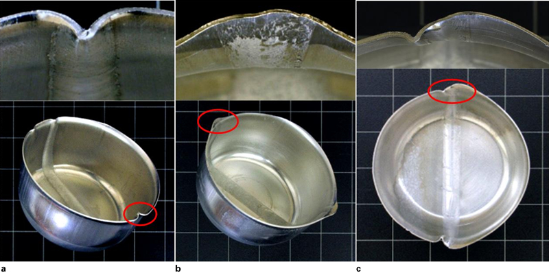
Leitão et al. 11 investigated the formability of similar and dissimilar friction stir welded AA 5182-H111 and AA 6016-T4 tailored blanks with deep drawing of cylindrical cups. The FSW process was used for joining the two base materials in similar (AA 5182–AA 5182 and AA 6016–AA 6016) and dissimilar (AA 5182–AA 6016) combinations. The welds were produced with 1 mm thick plates of both base materials, which were extensively characterised by performing monotonic tensile tests at several angles, namely, 0, 15, 30, 45, 60, 75 and 90° with the rolling direction. The mechanical properties of the welds were evaluated by performing tensile tests from longitudinal weld samples. Details of the mechanical characterisation works can be found in Leitao et al. 11 11,12 From these works, it is evident that the AA 5182 similar welds (S55) and the dissimilar ones (D56) were in overmatch relative to the base materials yield stress, but the AA 6016 similar welds (S66) were in undermatch. The formability of the TWBs was found to be strongly influenced by the type of mismatch in mechanical properties, between the weld and the base materials, and also, by the initial size of the blanks. In fact, defects at the cup flanges were observed in some tests, such as, strong wrinkling over the weld observed for the overmatched S55 cups (see Fig. 1a) and small earing at the welds observed for the undermatched S66 cups (see Fig. 1b). The D56 blanks counter the forming characteristics of the S55 and S66 blanks, displaying strong bending, at the AA 5182 flange side of the cups, and earing at the AA 6016 side of the TWB (see Fig. 1c). In the experimental work, the type of defects was simply related with the mismatch in mechanical properties between the weld and the base materials. However, the influence of the presence of weld material defects and/or weld geometry on defect formation should also be considered. From the present numerical simulation work, a strong relation was found between the weld bead geometry and defect formation for the overmatched TWBs.
Defects at weld bead edge
Numerical simulation procedure
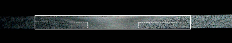
Three-dimensional isoparametric finite elements associated with a selective reduced integration scheme were used for the spatial discretisation of the TWBs. To investigate the influence of the weld geometry on defect formation, the numerical study was performed using several finite element meshes, with different modes of discretisation of the weld bead. In order to depict the options took for the finite element discretisation, a picture of the cross-section of a friction stir weld is shown in Fig. 2, where the shallow bowl shape typical of this type of weld is visible. Considering the shape of the weld and extremely small plate thickness, two different modes of discretisation of the weld line were tested, namely, a simplified discretisation of the weld (considering a rectangular weld cross-section, see solid contour in Fig. 2) and a ‘realistic’ discretisation of the weld (using a non-uniform weld cross-section, see dashed contour in Fig. 2). For the TWBs corresponding to the simplified discretisation, two finite element meshes were constructed with 4 (Fig. 3a) and 12 (Fig. 3b) finite elements across the weld domain which represent 4 mm (width of the weld root) and 12 mm (width of the weld crown) large welds. These meshes were labelled L4 and L12 respectively. For the ‘realistic’ discretisation of the welds, two different types of meshes were constructed, namely, meshes using two different layers of finite elements in the weld domain, one with the weld crown width (12 mm) and the other with the weld root width (4 mm), as shown in Fig. 3c, and meshes using three layers of finite elements, as shown in Fig. 3d, which better represent the real weld shape. For the ‘realistic’ type of meshes, two situations were simulated considering different TWBs positioning relative to the punch, namely, the situation in which the weld root is in contact with the punch (meshes L4.12 and L4.8.12 in Fig. 3c and d respectively) and the situation in which the weld crown is in contact with the punch (meshes L12.4 and L12.8.4 in Fig. 3e and f respectively). Finally, based on the geometry of the TWBs (picture in Fig. 4a), a quarter of the blank was modelled for the similar TWBs (Fig. 4b) and a half of the blank was modelled for the dissimilar TWBs (Fig. 4c).
Transverse cross-section of weld
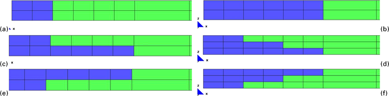
Finite element meshes (green part is base material and blue part is weld material) corresponding to a–d different types of discretisation of weld cross-section and c–f different orientations of TWBs relative to stamping tool
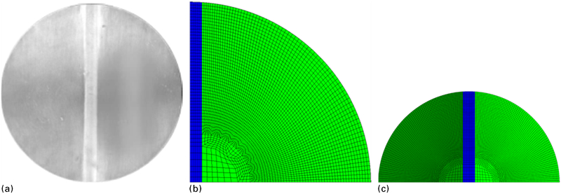
a experimental TWB, b finite element mesh of similar TWB and c finite element mesh of dissimilar TWB
In order to simulate the cylindrical cup deep drawing test, an in house
three-dimensional implicit finite element code (DD3IMP) was used. Details
of this framework can be found in Menezes and Teodosiu13 and Oliveira et al.
14 Owing to the very limited range of mechanical characterisation
data available for the welds, to describe the mechanical behaviour of the
materials Hill-48 orthotropic yield criteria was used, combined with isotropic
hardening, described by the saturation law

 is the equivalent stress, σ0
is the initial yield stress, Rsat is the saturation
stress and nv is a constant. The material parameters
for the base materials and welds, which were determined by Leitao et
al.
12 and Rodrigues et
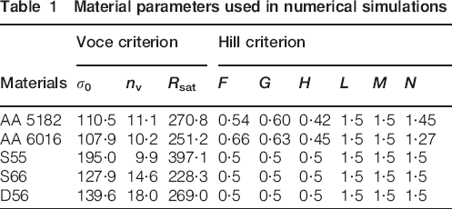
al., 15 are shown in Table 1. In the table, F, G, H, L, M and N are the Hill coefficients of
anisotropy. The weld materials were considered isotropic (F = G = H = 0·5 and L = M = N = 1·5) due to the extreme difficulty in characterising
the plastic anisotropy of the welds.
is the equivalent stress, σ0
is the initial yield stress, Rsat is the saturation
stress and nv is a constant. The material parameters
for the base materials and welds, which were determined by Leitao et
al.
12 and Rodrigues et
al., 15 are shown in Table 1. In the table, F, G, H, L, M and N are the Hill coefficients of
anisotropy. The weld materials were considered isotropic (F = G = H = 0·5 and L = M = N = 1·5) due to the extreme difficulty in characterising
the plastic anisotropy of the welds.
Material parameters used in numerical simulations
The deep drawing tools, dimensions shown in Fig. 5a, were modelled with Bézier surfaces. Figure 5b shows the model used for the numerical simulations of the similar TWBs. A blank holder force of 8 kN, similar to that used in some of the experimental tests conducted to produce cups shown in Fig. 1, was used in the numerical simulations.
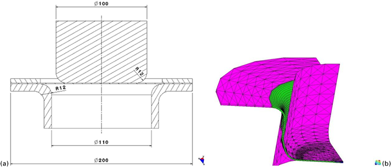
a scheme of deep drawing tools and b finite element model
Results and discussion
The different mesh configurations, as described in the previous section, were used in the simulations to investigate the influence of weld bead geometry on the formability of the similar and dissimilar TWBs. The punch force–displacement curves, from all simulations performed for the S55 TWBs, are shown in Fig. 6. As it can be observed from the graph, all curves are similar in spite of different weld bead geometries and dimensions. At a punch displacement of 45 mm, an abrupt force drop was observed in all tests, which corresponds to the moment at which the TWB dissociates from the blank holder and this point forms the threshold for defect initiation. The drawing forces diminish which reduce the load on the punch. At the unsupported section, between the blank holder and the punch, the blank tend to become unstable and form wrinkle or buckle releasing the compressive hoop stress induced during draw-in. Thus, a momentary, sharp drop in the punch force is inevitable. From there onwards, the punch force evolution is partially governed by weld bead edge defect formation, if any, and some differences can be observed between the evolutions of the curves plotted in Fig. 6. The same trend was observed in simulations performed with the S66 and D56 TWBs, and for this reason the results were not included in the present paper.
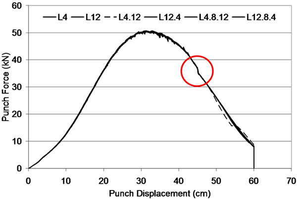
Punch force evolution for S55 TWBs
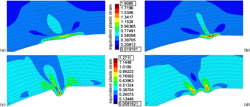
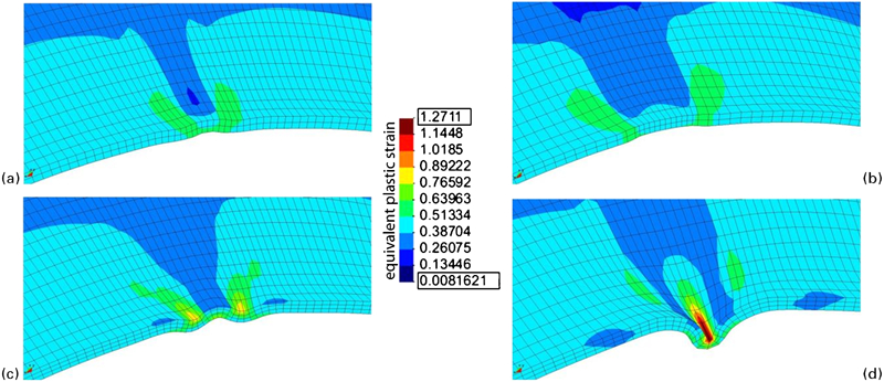
The final shape of a dissimilar, deep drawn cup (56_L12.4), with equivalent plastic strain distribution, is shown in Fig. 7. It is important to emphasis that the global equivalent plastic strain distribution in the deep drawn cups is similar for all TWBs and mesh configurations, except at the cups flange, in the vicinity of the weld, where different types of bead edge defect is observed depending on the TWB. Figure 8 shows the equivalent plastic strain distribution at the weld bead edge, for S66 and S55 TWBs. As shown in the figure, the blank orientation (L12.4 and L4.12 mesh orientations) as well as the type of mismatch in mechanical properties (over- or undermatch) affects the part quality significantly. In the undermatched TWBs (Fig. 8a and b), small ears at the weld bead, very similar to that observed in the experimental tests (Fig. 1b), can be observed for both mesh orientations. In fact, for the undermatched TWBs, the defect geometry is the same despite different amounts of plastic deformation observed with the different weld configurations represented in Fig. 3. This indicates that the defect formation is independent of the weld geometry.
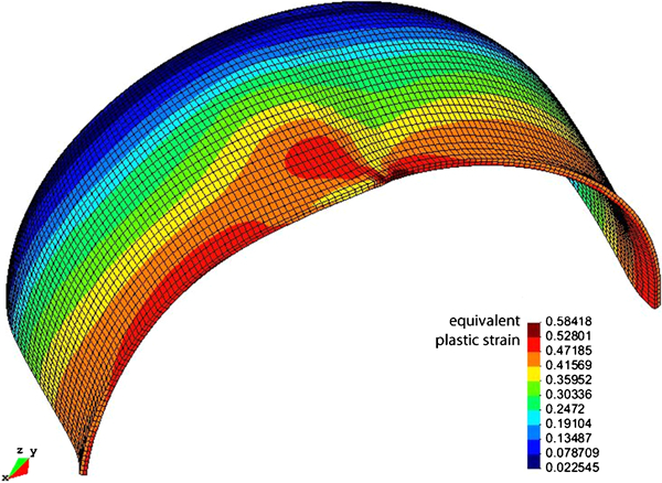
Equivalent plastic strain distribution in 56_L12.4 TWB cup
Edge defects in S55 and S66 cups
Unlike S66 TWBs, the S55 overmatched TWBs weld bead edge crumpled with a single fold inwards in L4.12 mesh configuration (Fig. 8c), similar to that observed in the experiment (Fig. 1a), while two folds were formed in L12.4 mesh configuration (Fig. 8d). These results indicate a strong influence of TWB positioning relative to the punch on defect formation. In Fig. 9a–d, the same type of S55 results are shown, but for the L4, L12, L4.8.12 and L12.8.4 meshes respectively. From the figure it is possible to conclude that for the simple descritisation (L4 and L12 meshes), a narrow weld bead induces less plastic strain (Fig. 9a) compared to a wide weld bead (Fig. 9b) and no defect formation at the weld bead edge. In Fig. 9c and d, which shows the equivalent plastic strain distributions for the L4.8.12 and L12.8.4 mesh configurations respectively, it is possible to see the same defect configurations already observed with the L4.12 and L12.4 meshes (Fig. 8c and d respectively) which shows that using one more finite element layer in the thickness direction did not change the predictions. However, results in Fig. 9 clearly point to the importance of the weld bead geometry on defect formation in overmatch conditions.
Edge shapes in S55 cups
Finally, comparing the weld bead edge shape in the numerical simulation of the dissimilar TWBs, which is shown in Fig. 7, with the experimental result displayed in Fig. 1c, it is evident that the numerical model is unable to capture the occurrence of a fold at the overmatched side of the D56 TWBs, despite the non-uniform weld cross-section used in the numerical simulation. The same type of edge shape shown in Fig. 7, is obtained with the D56_L4.12 configuration.
However, it is important to emphasise that the mechanical properties of the dissimilar welds were taken from longitudinal weld samples. Therefore, the properties are considered uniform across the weld section in the numerical model, which does not accurately represent the real welds. The real welds display a gradient of properties across the weld, as shown in Leitão et al. 12 where the hardness distribution across the welds can be found. Therefore, the discrepancies between the numerical and experimental results can be attributed to an incorrect description of mechanical properties gradient across the weld.
Some discrepancies between the numerical and experimental results were also found for the S55 TWBs, since the formation of a single fold was observed for the L4.12 mesh, while in the experimental work this type of defect was observed in cups obtained with reverse blank orientation (Fig. 1a), which actually corresponds to the L12.4 configuration in the numerical work. Since the same type of results were obtained with the more refined models (L12.8.4 and l4.8.12 meshes), the discrepancies between the numerical and experimental results can only be related with an inaccurate description of the gradient in mechanical properties across the weld width and thickness. In fact, Laurent et al. 16 have found that the tangential stress gradient through the thickness, which is closely related with the gradient in local mechanical properties and mesh discretisation scheme, play a dominant role in initiating defects.
In order to further analyse the influence of the weld geometry and of the mechanical properties gradient on defect formation, in the overmatched TWBs, some new configurations were modelled, namely, meshes (L4.0 and L0.4) and (L8.0 and L0.8), in which the weld is represented as a very narrow line with 4 and 8 mm width respectively, extending only up to the mid sheet thickness (see examples in the graphs of Fig. 10), and also, meshes with varying weld crown width, namely, meshes L4.14 and L14.4 (14 mm crown width) and meshes L4.10 and L10.4 (10 mm crown width). Figure 10 shows profiles of the deep drawn cups, corresponding to a cut at the middle of the weld with the narrow weld root (Fig. 10a) and the wide weld crown (Fig. 10b) surfaces in contact with the punch. In the same figure, images of the plastic strain distribution near the weld edge are included, for the new configurations modelled. Comparing the cup profiles, and taking as reference the profile of the L4 mesh, which lead to defect free cup forming (see Fig. 9a), it is possible to confirm that weld defect type is related with material distribution in the weld domain. In fact, the formation of one fold at the middle of the weld line, as was observed in the experimental work, was previewed in the numerical simulation analysis whenever a small portion of material with overmatched mechanical properties, distributed over a very small width (4 mm), was modelled at the cup wall in contact with the punch (L4.x meshes). By modelling the overmatched material uniformly distributed across the entire cup wall thickness (L4 mesh), or distributed along a wider width at the cup wall in contact with the punch (L8.0 mesh), no defect formation was previewed. The formation of two small folds, one at each side of the weld line, which was not observed in the experimental work, was previewed for all the other situations modeled. These results point for a strong influence of both weld shape and distribution of material properties, across the weld width and thickness, in defect formation.
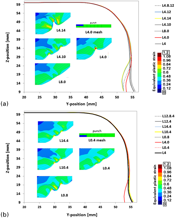
Cup profiles for S55 TWBs with a narrow weld root and b wide weld crown surfaces in contact with punch
Defect formation in the overmatched TWBs was further analysed using the prevailing stress state in the formed cup. During forming, the blank is subjected to bending, unbending and stretching which results in the accumulation of different magnitudes of strains at different locations. These accumulated strain distributions can be characterised by the tangential stresses. Figure 11a shows the tangential stress state across the cup inner wall, at a depth of 30 mm from the edge, for some of the numerical simulations performed in the present work. According to the figure, the tangential stresses at this level of the cup are compressive with minimal variation in the simple narrow weld geometry (L4). In the non-uniform weld bead geometries, the variation is much higher, especially around the weld bead (90° angle), as shown in the figure. Owing to the shape of the weld bead geometry and overmatched characteristics, the weld bead/base material interface behaves like a couple. The moment due to this couple initiates the defect, the shape of which depends on the surface in contact with the punch. When the top surface of the weld is in contact with the punch, a double fold occurs at the weld bead edge which causes the large compressive stresses around the weld, as shown in the figure. When the root of weld bead is in contact with the punch, a deep single fold defect occurs at the weld bead edge relieving part of the compressive stress. At the edge of the cup, little tangential stress remains in the cup as shown in Fig. 11b.
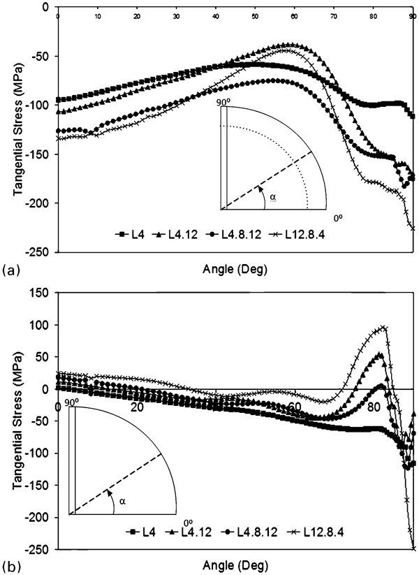
Tangential stress across cup inner wall a at depth of 30 mm from edge and b at edge
Conclusions
A study concerning the influence of the weld bead shape on defect formation during deep drawing of friction stir welded TWBs, was conducted in the present work, using numerical simulation. With this aim, several finite element mesh configurations were constructed and numerical simulations of cylindrical cups drawing were performed. Comparison of the numerical results with experimental ones shows that numerical analysis is able to explain the observed experimental behaviours. The present study confirms that the formability of the TWBs is strongly influenced by the type of mismatch in mechanical properties between the weld and the base materials. When the weld is in overmatch relatively to the base material, a strong influence of the weld bead geometry and distribution of material properties across the weld cross-section, on defect formation, is detected. Little influence of weld shape on defect formation was detected when the weld is in undermatch condition. According to the present study, for overmatched TWBs, regular weld bead geometries, corresponding to constant weld width and uniform distribution of material properties across the plate thickness, does not conduct to major defect formation during deep drawing of TWB cups. However, for weld geometries characteristic of FSW joints, with non-uniform weld cross-section and a complex distribution of material properties across it, the cup edge will crumple, inside or outside, depending on the weld characteristics. This is due to the tangential stress present in the component blanks and the instability arising in the weld bead.