
Abstract
The rotational direction of the friction stir welding (FSW) tool plays a role as important as the weld parameters in FSW processes for magnesium alloys. The formation quality of the weld joints strongly relies on the rotational direction of the stir tool. Based on the present results the better tensile properties of the weld joints are achieved by welding at a higher rotational speed no matter what direction the stir tool rotates. The face bend properties are superior to the root bend properties of the joints. The optimal weld parameters are 1500 rev min−1/90 mm min−1 and 1200 rev min−1/60 mm min−1 for the clockwise and counterclockwise directions of the stir tool respectively. Regardless of the direction which the tool rotates in, fractures of the tensile specimens are mostly located at the boundary between the thermal mechanical affect zone and the nugget zone.
Introduction
As a structural material that may potentially be applied in the automobile and aviation industries, magnesium alloys have attracted extensive international attention.1 However, their poor weldability is often manifested by a large heat affected zone (HAZ), high porosity, evaporative loss of alloying elements and high residual stresses.2 Thus, great challenges remain in terms of improving the weldability of magnesium alloys for more structural applications. To overcome these disadvantages, an alternative method known as friction stir welding (FSW), invented by TWI in 1991, has been developed.3 Although FSW technology has been successfully applied to different aluminium alloys in the past decade, some issues remain regarding the FSW weldability of magnesium alloys.4
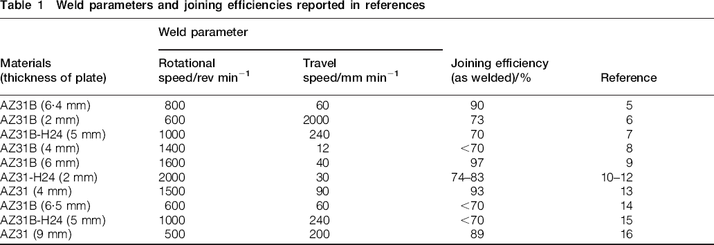
Previous investigations on the microstructure and properties of the friction stir welded joints of magnesium alloys have indicated that the microstructures of the stir zone present some characteristics similar to other materials after FSW, such as dynamic recrystallisation, equi-axed grains, and deformation dislocation and twinning.5 By increasing the shoulder diameter or the tool rotation speed and decreasing the weld speed, 6 6,7 the heat generated during the welding process is increased and grain growth is promoted. Tensile strength increases with increasing the travel speed or decreasing the rotational speed in a range of weld parameters.6 Fracture positions are located mostly at the boundary between the nugget zone (NZ) and the thermal mechanical affect zone (TMAZ) toward the advancing side, and fracture surfaces show a mixture of cleavage-like and dimple-like characteristics. 6 6,8 Generally, joining efficiency, defined as the ratio of the joint strength to the base metal (BM) strength, is always considered as an important criteria to evaluate the mechanical properties of the weld joints. Some research results are summarised in Table 1, which shows that the maximum and minimum values of the joint efficiency are ∼93% and <70% for AZ31 magnesium alloys respectively. Such a large fluctuation of the joint efficiency indicates that the joining efficiency did not exhibit close correlation with weld parameters. Moreover, the factors affecting the microstructural and mechanical properties of friction stir welded magnesium alloy joints can not only be simply attributed to weld parameters, such as rotational and travelling speeds, but also to other factors not yet investigated, such as the shape, size and rotational direction of the stir tool.
Weld parameters and joining efficiencies reported in references
As well known, the flow ability of magnesium alloys is relatively poor during FSW processes due to their close packed hexagonal crystal structure. The rotational direction of a stir tool has an important effect on the flow of the softened metal around it, particularly in stir tools with the screw thread on the pin. The improvements of the flow ability of the magnesium alloys around the stir tool rely on not only the weld parameters, but also the rotational direction of the stir tool. Balasubramanian et al. 9 mainly studied the effect of the pin profile on the formation quality and tensile properties of the friction stir welded joints of AZ31 magnesium alloys. Chowdhury et al. investigated the effect of weld speeds, rotational rates and pin tool thread orientations on the microstructures and mechanical properties of friction stir welded joints for AZ31 magnesium alloys. They pointed out that the left hand thread pin tool rotating clockwise generated good friction stir welded joints and mechanical properties due to the downward material flow close to the stir tool surface, while the right hand thread pin tool turning clockwise caused an upward material flow and resulted in inferior joints.10– 12 The similar results had also been reported in the friction stir welded joints of aluminium alloys.17– 20
However, the previous works on the FSW of the magnesium alloys were carried out within a certain range of weld parameters. The key problem which range of the weld parameters, higher or lower rotational and travel speed, is suitable for the FSW of magnesium alloys, is still unclear. Thus, in the present work, two rotational directions of the stir tool, clockwise and counterclockwise, are employed to systemically investigate the effects of stir tool rotational direction on the microstructures and mechanical properties of friction stir welded joints of alloys over a wider range of weld parameters. The aim is to find optimal weld conditions and weld parameters of the friction stir welded joints of AZ31B magnesium.
Experimental procedure
An AZ31B alloy extruded sheet with a gauge thickness of 4 mm was used for FSW. The chemical composition of the sheet was Mg–3Al–1Zn–0·5Mn (wt-%). The FSW was performed perpendicular to the rolling direction of the sheet on an FSW machine manufactured by China Friction Stir Weld, Ltd, Beijing. The stir tool was made of H13 steel and composed of a shoulder and a pin as shown in Fig. 1. Key dimensions of the stir tool are D = 12 mm, d1 = 6 mm, d2 = 3 mm and L = 3·8 mm. A right hand screw thread was present on the pin surface. The stir tool rotated in both the clockwise and counterclockwise directions. Travelling speeds varied from 30 to 1200 mm min−1, and rotational speeds varied from 600 to 1200 rev min−1. The axial force was obtained by controlling the plunge depth to 0·1 mm. The tilting angle of the tool axis was 2° in relation to the normal direction of the plate surface.
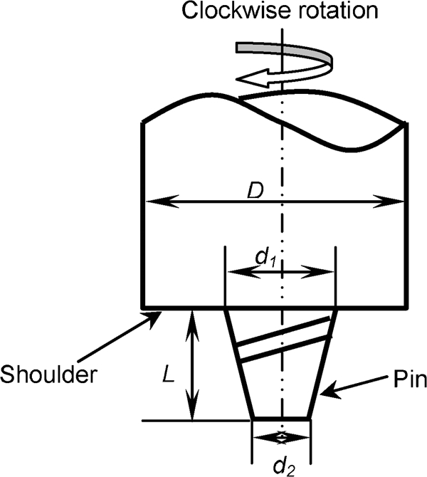
Profile of stir tool
Specimens for the tensile test were prepared according to the corresponding standard for weld sheets and plate materials. The shape, size and cutting direction of the tensile samples are illustrated in Fig. 2. Tensile tests were performed at room temperature and at a strain rate of 6·0×10−4 s−1. Two kinds of bend tests, face bend and root bend, were employed to evaluate the bend angle of the weld joints.
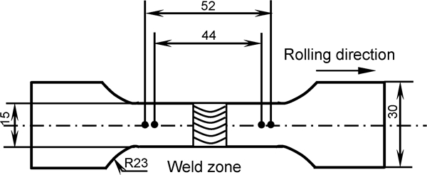
Shape and size of tensile specimens
The metallographic observation samples were cut perpendicular to the weld direction at cross-sections of the weld joints. After mechanical grinding and polishing, the samples were etched in a solution of 4·2 mL picric acid, 10 mL acetic acid and 100 mL ethanol. Microstructure examinations were carried out using an optical microscope. The fracture surfaces obtained after the tensile tests were observed using a HITACHI S-4800 scanning electron microscope.
Results and discussion
Microstructures
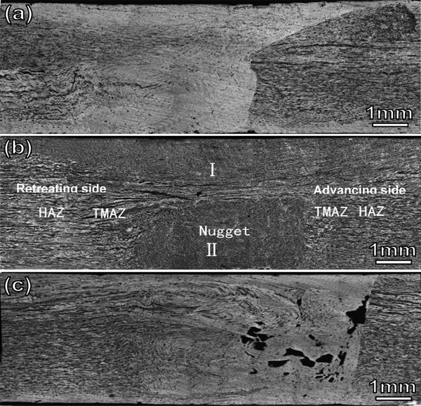
Typical macrographs at the cross-section of the weld joints welded under three typical weld parameters and with the tool rotating in clockwise direction are shown in Fig. 3. Friction stir welded joints of magnesium alloys can also be divided into four zones, similar to aluminium alloys. These zones are: NZ, TMAZ, HAZ and BM. From Fig. 3, the boundary between the welded zone and the BM at the advanced side of the weld joints is clearer than that at the retreated side. By increasing the rotational speed, the size of the welded zone becomes larger and the ‘onion’ feature in the middle welded zone becomes less evident. The metal flow at the bottom of the advanced side exhibits an abnormal flow path in weld joints welded at rotational speeds of 900 and 1200 rev min−1 (Fig. 3a and b respectively). Consequently, tunnel weld defects and insufficient penetration are found in these abnormal regions (as the arrow shown in the figure). When the rotational speed increases to 1500 rev min−1, the tunnel defects disappear (Fig. 3c).
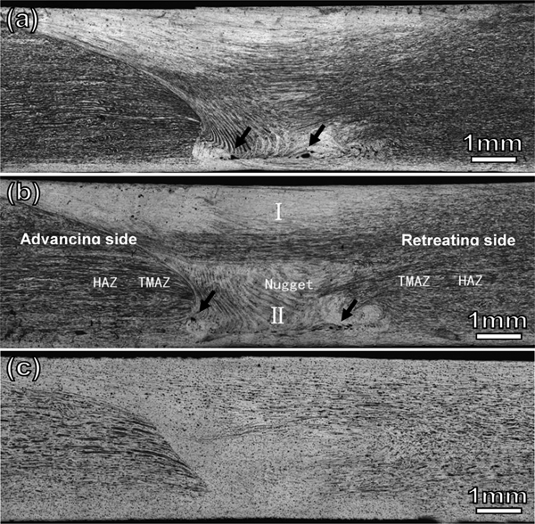
Macrostructures of weld joint welded with stir tool rotating in clockwise direction and different weld parameters
The formation of the above defects under the stir tool rotating in clockwise direction is related to the flow ability and the flow paths of the metal materials around the stir tool. Generally, the metal flow in the weld joints can be divided into two zones: zone I, where the softened metal driven by the shoulder exhibits a horizontal flow around the longitudinal axis of the stir tool, and zone II, where the softened metal driven by the screw thread on the pin exhibits a downward or upward spiral flow with respect to the rotational direction of the stir tool. When the stir tool rotates clockwise, besides the horizontal flow of the metal driven by the shoulder in zone I, there is a flow from zone I to II driven by the pressure force of the shoulder. In zone II, the upward spiral flow driven by the stirring of the screw thread on the pin occurs first. Then, the metal at the bottom position of the joints are also driven to flow upward due to the ‘chimney effect’.21 Meanwhile, the metal from zone I will be driven downwards along the boundary near to the TMAZ and mixed with the metal at the bottom zone. However, because the temperatures of the bottom metal and the area near the TMAZ are lower than that at the upper metal, the flow mentioned as above are not enough. As a result, weld defects form at the bottom position of the joints.
To obtain the sound flow of magnesium alloys around the stir tool, heat input, which is strongly dependent on the weld parameters, must be adequate to soften these metals. By increasing the rotational speed or decreasing the travelling speed, heat input can be enhanced. Consequently, the flow ability and banding or mixing of the softened metal are improved and defects are avoided (Fig. 3c). The above results indicate that higher heat input is an essential condition for FSW of magnesium alloys.
In comparison, when the stir tool rotates counterclockwise, the direction of the extruded force from the pin of the stir tool contrasts with the case where the stir tool rotates clockwise. Therefore, the flow direction of the softened metal around the pin is opposite to that in the clockwise direction, i.e. the softened metal migrates from the top toward the bottom regions of the weld joints. Furthermore, the variation of the flow paths can result in significant differences in some microstructural features, particularly when compared with that in the clockwise direction. Figure 4 shows three typical micrographic cross-sections of the weld joints welded with the stir tool rotating counterclockwise.
Macrostructures of weld joint welded with tool rotating in counterclockwise direction and different weld parameters
The location of the weld nugget in the cross-section is observed to have shifted downwards to the bottom zone. The problem of insufficient penetration, which easily forms at the root of the weld joints welded in the clockwise direction, is effectively resolved (Fig. 4a and b). It means that FSW technology with the tool rotating in the counterclockwise direction appears to be an effective method for resolving the problem of weak boundaries at the bottom of the weld seam, which have been regarded as inherent defects of FSW.22
From Fig. 4c, severe porosity defects are formed at the advanced side of the weld joint welded at a low rotational speed of 600 rev min−1 and a travel speed of 601 mm min−1. The formation of these porosity defects is related to the flow path in the counterclockwise direction. This can be explained as follows: the flyer formed at the retreated side of the weld joints breaks the volume balance in the weld zone such that the metal cannot completely fill the rear of the trailing edge. As well, because the heat input is lower, the cooler metal at the defect region cannot sufficiently flow or mix, thus forming several pores.
Mechanical properties
Tensile properties
The ultimate tensile strength (UTS) of the joints welded with the stir tool rotating clockwise and counterclockwise are shown in Fig. 5a. The UTS of all weld joints are lower than that of the BM (∼305 MPa in the present test). When the stir tool rotates in clockwise direction, the UTS of the joints welded in the rotational speed range of 1200–1500 rev min−1 is better than that of 600–900 rev min−1. The largest UTS is ∼293 MPa in the joint welded by the stir tool rotating clockwise at a rotational speed of 1500 rev min−1 and a travelling speed of 90 mm min−1. While the stir tool rotates in counterclockwise direction, the better tensile properties merge in all range of weld parameters.
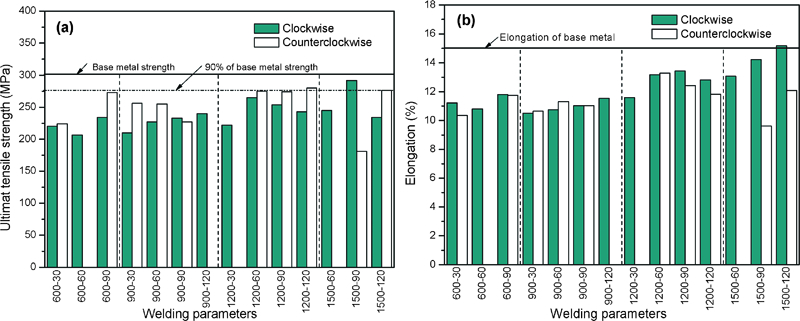
a UTS and b elongation of specimens welded with stir tool rotating in clockwise and counterclockwise directions
In the present work, the maximum joining efficiencies of weld joints welded by the stir tool rotating clockwise and counterclockwise are about 96 and 92% respectively. Although the maximum joining efficiency in the counterclockwise direction is lower than that in the clockwise direction, the range of weld parameters at which the joining efficiency can exceed 90% is expanded for the counterclockwise direction (Fig. 5a, 90% line). Owing to differences in tool rotational directions, the softened metal could fully undergo different thermal mechanical actions. As a result, variations of the microstructures in the TMAZ and HAZ occur, resulting in differences in their mechanical properties. The presence of weld defects in the welded zone should not be ignored and must be considered an important factor that affects the mechanical properties of weld joints.
Variation of the UTS with increasing rotational and travelling speeds for both rotational directions of the stir tool can also be seen in Fig. 5a. In the clockwise direction, the UTS increases with increasing travelling speed for the weld joint welded at a rotational speed of 900 rev min−1. The relationship between the UTS and the rotational speed exhibits good linear features. However, the variations of the UTS with other weld parameters do not exhibit good linear relationships for derivations of other data. In the counterclockwise direction, only the relationship between the UTS with a rotational speed of 1200 rev min−1 exhibits good linearity. The similar linear relationships between the UTS and the weld parameters had also been reported in some research works.9– 12
Variations of the elongation as a function of the weld parameter are shown in Fig. 5b. A maximum elongation that is slightly higher than that of the BM occurs in the clockwise direction for the weld joint welded at a rotational speed of 1500 rev min−1. The elongation increases when the rotational and travelling speeds are increased in the clockwise direction. In the counterclockwise direction, the trend of variation does not exhibit monotonic increases with increasing rotational speed at all ranges of the weld parameters. For example, the elongation decreases with increasing travel speed for the weld joint welded at a rotational speed of 1200 rev min−1 and with the tool rotating counterclockwise. The mechanical properties above indicate that the tool rotational direction has a significant effect on the mechanical properties. Meanwhile, the monotonic variation relationship between mechanical properties and weld parameters only occur over a certain range of weld parameters. That means the discreteness of the data and the effect of weld defects must be paid more attention.
Bending properties
The bend test can evaluate both the bend strength and the weld defects in the root or face region of the weld joints. Two bending tests, the face bend (the frontal face of the weld endured stretch stress) and the root bend (the back root of the weld endured stretch stress), are carried out to examine the bend angle of the joint welded in different rotational directions of the stir tools with different weld parameters. The results are shown in Fig. 6. From the face bend test results shown in Fig. 6a, it is evident that the face bend properties of the joints welded by the stir tool rotating clockwise were superior to those welded by the stir tool rotating counterclockwise. Moreover, the rotational and travel speeds have no significant effects on the bend angle for joints welded with a stir tool rotating clockwise. Larger bend angles are achieved for weld joints welded at all ranges of the weld parameters in the clockwise direction. The better face bend property under the case of clockwise may be related to the lower tendency of the weld defects on the upper region of the weld joints. While the weld defect can be mostly formed at these positions under the case of counterclockwise and result in poor face bend property.
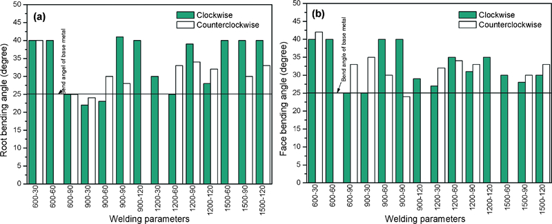
Comparison of bending angles of joints welded with stir tool rotating in clockwise and counterclockwise directions
The root bend test results are show in Fig. 6b. Compared to Fig. 6a, it can be seen that the discreteness of the bend angle is obvious. Although the total quantity of the weld joints, whose root bend angles exceed that of the BM, is larger than that of the weld joints in the face bending test, their resistance to bending in the face of the FSW joints is superior to that in the root. It reveals that no matter what direction the stir tool rotates, the root of the weld joint will always be the weakest position for the tensile fracture. The weak joining at the root of the friction stir welded joints had been discussed for many years. It is not only related to the flaw path of soften metal around the stir tool, but also to the length of the pin and the penetrating depth of the shoulder. In other words, the problem of this weak joining at the root of the joints cannot be thoroughly solved by controlling the flaw path of the soften metal. The moderated size of the pin and depth of the shoulder play a more important role in restricting this problem.
After comparing the results of the tensile test, it can be seen that the one-to-one correspondence between two mechanical properties is not good. Comparatively speaking, weld joints with higher tensile properties and larger face and root bend angles are always welded at higher rotational and travel speeds in both rotational directions of the stir tool. The optimal weld parameter in the clockwise direction is 1500 rev min−1/90 mm min−1, while that in the opposite direction is 1200 rev min−1/60 mm min−1. This suggests that magnesium alloys are preferably welded at higher ranges of weld parameters no matter what direction the stir tool rotates.
Tensile fracture feature
The fracture failure of tensile specimens mostly occurs along the boundary between the NZ and TMAZ on the advancing or retreated side, except for the two specimens that welded at a lower rotational speed failed on the weld NZ. Such failure may be due to NZ defects. The fracture angle of all specimens welded with the stir tool rotating clockwise and counterclockwise is ∼45° with respect to tensile direction. This means stir tool rotational direction has no effect on the fracture mode.
Figure 7 shows two typical fracture surfaces of specimens welded with the stir tool rotating clockwise. The fracture surfaces of all specimens without weld defects that failed at the boundary between the NZ and TMAZ exhibit mixed features of cleavages and dimpled ruptures (Fig. 7a). By increasing rotational and travelling speeds, the ductile features become more prominent. However, for the joints welded at a lower rotational speed that failed in the NZ (Fig. 7b), a groove resulting from the tunnel defects near the bottom surface of the specimen is obviously distinguished (the arrow shown in Fig. 7b). The fracture surfaces of the joints welded with the tool rotating counterclockwise are not displayed here due to their similarity to those of joints welded with the tool rotating clockwise.
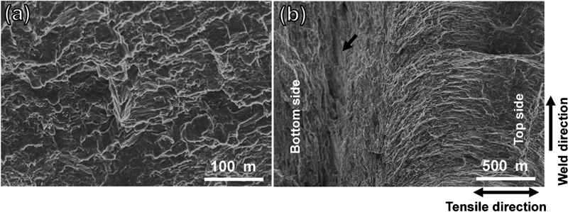
Fracture surface of tensile specimen welded with stir tool rotating clockwise
Conclusions
The tool rotational direction has obvious effects on the microstructures and mechanical properties of friction stir welded magnesium alloys.
When the stir tool rotates clockwise and the heat input is insufficient, porosities are easily formed and insufficient penetration at the bottom occurs. These defects can be reduced by the counterclockwise rotation of the stir tool, which varies the flow of softened metal around the stir tool and results in a downward shift of the NZ.
The stir tool rotating counterclockwise is beneficial to improving the mechanical property of the weld joints. Maximum joint efficiencies of 96 and 92% are achieved under clockwise and counterclockwise rotations respectively. No matter what direction the stir tool rotates, the face bend property is superior to root bent property of the joints.
Magnesium alloys are preferably welded at higher ranges of weld parameters. Under the present weld conditions, the optimal weld parameters are 1500 rev min−1/90 mm min−1 and 1200 rev min−1/60 mm min−1 for the clockwise and counterclockwise directions of the stir tool respectively.
The tensile fracture feature exhibits no significant difference between the tool rotating clockwise and the tool rotating counterclockwise. The tensile fracture always occurs along the boundary between the NZ and TMAZ. The fracture angle is ∼45° with respect to the tensile direction, which displays a shear fracture mode. Most facture surfaces exhibit mixed features of cleavages and dimpled ruptures.
Footnotes
Acknowledgements
The authors acknowledge financial support from the National Science Foundation for Distinguished Young Scholars (grant no. 50925522).