
Abstract
Morphological, metallographic and structural analyses of aluminium–copper dissimilar welds produced under different friction stir welding conditions were conducted in order to analyse the mechanisms of intermetallic phases formation, its relation with welding conditions and its consequences in the weld structure and morphology. Under lower heat input conditions, only a thin intermetallic layer distributed along the aluminium/copper interface was depicted inside the nugget. Increasing the heat input promoted material mixing and formation of increasing amounts of intermetallic rich structures. The intermetallic phase content and the homogeneity of the mixed area increased with increasing heat input, evolving from structures containing Al, Cu, CuAl2 and Cu9Al4 to structures predominantly composed of Cu9Al4 and Cu(Al). In order to explain these results, the mechanisms of intermetallic phases formation are discussed, taking into account the process parameters and material flow mechanisms in friction stir welding. Important relations between intermetallic formation and weld surface morphology were also found.
Introduction
The industrial application of the friction stir welding (FSW) technology has been driven by its potential for joining materials hardly weldable by traditional fusion processes as well as for dissimilar welding of materials with very different properties, such as aluminium to copper.1 Although some experiments in the FSW of aluminium to copper have already been reported, successful joining of these metals has not been achieved yet, and several issues still require extensive research.
The different physical and mechanical properties of the base materials as well as its chemical affinity make mandatory the optimisation of the welding parameters in order to provide adequate metal flow around the tool and, simultaneously, to prevent the formation of a large amount of brittle Al–Cu intermetallic compounds. Murr et al., 2 who were the first to analyse Al–Cu friction stir welds, focused their work on the study of the microstructure and metal flow during dissimilar welding of 6 mm thick copper (99·9%) to 6061-T6 aluminium. Their microstructural analysis allowed observing complex intercalated microstructures, with vortices throughout the weld zone, resulting from welded metals overlapping. Some years later, Ouyang et al. 3 studied the microstructure of 12·7 mm thick copper (99·9%) to 6061-T6 aluminium friction stir welds, detecting the presence of a mixed region with several intermetallic compounds, such as CuAl2, CuAl and Cu9Al4. Ouyang et al.3 also observed a high disparity of mechanical properties in the nugget of the welds, specifically the hardness, which varied between 136 and 760 HV0·2. More recently, Xue et al.4 analysed 5 mm thick copper (99·9%) to 1060 aluminium friction stir welds. The authors observed in the nugget of the welds a bottom zone with a composite structure, which was formed by particles with different sizes dispersed in the aluminium matrix. The particles, mainly composed of CuAl2, Cu9Al4 and low amounts of CuAl, formed a local composite structure with higher mechanical properties than the aluminium base material. The formation of a continuous, thin and uniform intermetallic layer at the Al/Cu interface was also reported. This layer was predominantly formed of CuAl2 at the aluminium side and Cu9Al4 at the copper side. Finally, Galvão et al., 5 Xue et al. 6 and Liu et al. 7 reported the extremely high difficulty in producing non-defective Al–Cu welds with suitable surface finishing by comparing welds produced under different FSW conditions.
According to previous authors, the occurrence of important flow defects, the poor surface finishing and the formation of large amounts of brittle intermetallic structures in the nugget are the main problems in Al–Cu friction stir weldability. Comparing the data already published concerning the FSW of aluminium to copper also highlights the large scatter in welding results and the lack of information concerning the influence of the process parameters in intermetallic phase formation and its consequences in weld microstructure and morphology. This was the main objective of the current study, in which dissimilar friction stir welds of 1 mm thick plates of Cu-DHP and AA 5083-H111 were analysed.
Experimental
In the present work, 1 mm thick plates of oxygen free copper with high phosphorous content (Cu-DHP, R 240) and 5083-H111 aluminium alloy (AA 5083-H111) were friction stir butt welded. The welds were performed between the base materials using different processing parameters (varying traverse and rotation speeds) in an ESAB LEGIO FSW 3U equipment. A 14 mm diameter H13 steel tool with a 3° shoulder conical cavity and a 3 mm diameter cylindrical probe was used. The welds were produced with no tool's horizontal offset, under load control (700 kg) and using a tool tilt angle of 2°. Based on a previous study5 and in order to obtain the most adequate metal flow around the tool, the harder Cu-DHP plate was positioned at the advancing side of the tool in all the welds.
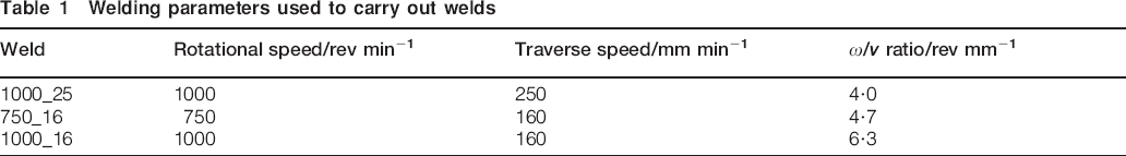
Table 1 displays the welding conditions used in this study. With reference to the testing conditions, the nomenclature adopted in the text to classify the welds identifies the rotational and welding speeds used. Thus, weld 750_16 is a weld performed with the rotational and welding speeds of 750 rev min−1 and 160 mm min−1 respectively. The tool rotation/tool traverse speed ratio ω/v, which is usually assumed as proportional to the heat input during the welding process,8– 12 is also presented in Table 1. The 1000_25 welding conditons (ω/v = 4·0 rev mm−1) will conduct to the lowest heat input during welding and the 1000_16 to the highest heat input (ω/v = 6·3 rev mm−1).
Welding parameters used to carry out welds
After welding, qualitative and quantitative macroscopic inspections of the weld surface were performed by visual inspection and image data acquisition using the ARAMIS optical analysis equipment respectively. The ARAMIS equipment enables to determine the variations in depth, inside the weld, relative to the base materials’ plate surfaces. Transverse cross-sectioning of the welds was performed for metallographic analysis. The samples were prepared according to standard metallographic practice. Metallographic analysis was performed using optical microscopy in a Zeiss HD 100 equipment. Scanning electron microscopy/energy dispersive X-ray spectroscopy (SEM/EDS) and micro-X-ray diffraction (XRD) were performed in the cross-section and on the surface of all the welds using a Philips XL30 SE microscope and a PANalytical X'Pert PRO microdiffractometer respectively. Fittings of the XRD patterns were performed with the PROFIT V1c software from Philips Electronics using pseudo-Voigt functions.
Weld morphology and structure
Results of the visual inspection of the weld surface are shown in Fig. 1. From Fig. 1a, it is possible to conclude that all the weld crowns are formed by a silver layer of irregularly distributed material. Figure 1b shows areas with significant accumulation of material (red areas) and areas with severe material absence (blue areas), which emphasises the strong discontinuity in material deposition during the process. This type of surface finishing, which is usual in dissimilar aluminium to copper friction stir welds5– 7,13 but never observed in Al–Al or Cu–Cu similar welds, constitutes one of the main concerns in Al–Cu joining due to its detrimental effect in both weld appearance and resistance.
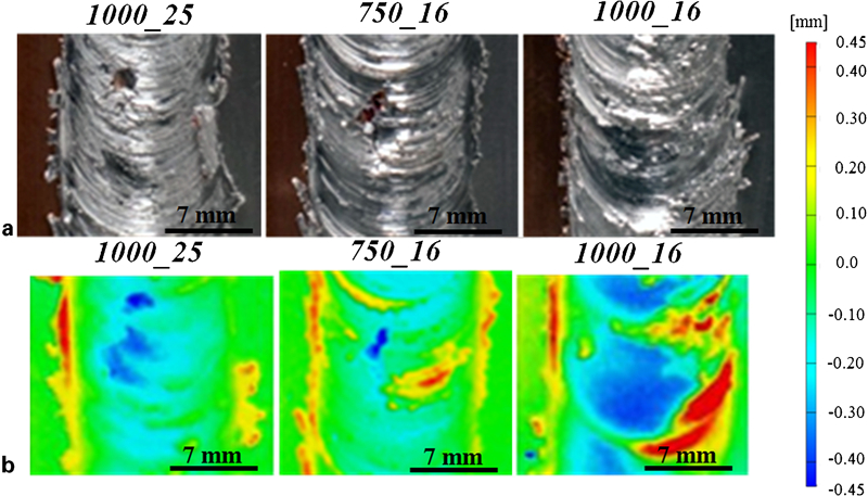
a images and b thickness spectra of weld crowns
Figure 2 displays optical macrographs of the transverse cross-sections of the welds and SEM images, acquired in backscattered electron (BSE) mode, of the selected weld areas. In order to facilitate the analysis, the pin and shoulder influence areas are indicated in each cross-section using vertical lines. Comparing all the macrographs, two common features can be observed: the presence of an aluminium layer at the top of all the welds, which was pushed from the retreating to the advancing side of the tool, and the presence of copper at the bottom of the welds. Despite these similarities, significant differences can also be observed by comparing the different nugget morphologies.
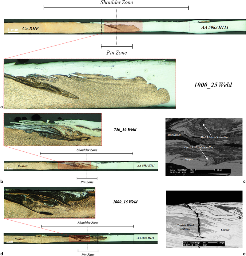
Macrographs of traverse cross-sections of a 1000_25, b 750_16 and d 1000_16 welds and backscattered electron (BSE) images of mixing zone of c 750_16 and e 1000_16 welds
As shown in Fig. 2a, in the 1000_25 weld, which was obtained under the lowest heat input conditions (ω/v = 4·0 rev mm−1), the base materials are completely separated by a sharp and well defined interface at the weld nugget. The low heat input did not provide enough energy for material mixing, which resulted in an interface morphology similar to that obtained by other authors when performing friction diffusion bonding.14 In the 750_16 weld (ω/v = 4·7 rev mm−1), shown in Fig. 2b, a mixed region is observed, composed of bright and dark zones, extending to the copper side of the pin zone. The BSE image in Fig. 2c, which was acquired inside this area, displays complex mixing patterns composed of layers of copper and aluminium alternated with copper or aluminium rich mixed lamellae. In the weld produced under the highest heat input conditions (ω/v = 6·3 rev mm−1), i.e. the 1000_16 weld (Fig. 2d), the top aluminium layer is only visible in the upper right part of the pin zone and is much thinner than in the previous welds. In this weld, a large mixing area, embedded in a copper matrix, is observed. The mixing zone is much larger than in the previous welds, extending out of the pin zone through both the aluminium and copper sides of the weld. Furthermore, the BSE image in Fig. 2e, which was acquired in this mixing area, shows an almost homogeneous mixture, in which only copper and copper rich mixed structures are discernible. It is important to note the presence of a crack, which propagates along the mixing patterns, indicating the extreme brittleness of these structures. Comparing all the welds in Fig. 2, it is possible to conclude that increasing the heat input resulted in the formation of mixed material zones with increasing dimension and homogeneity.
The results of the XRD analysis performed in three different locations of the weld nugget are shown in Fig. 3. All the XRD patterns obtained in the 1000_25 weld nugget (Fig. 3a) show intense fcc Al and fcc Cu peaks corresponding to the aluminium and copper parts of the nugget. Low intensity XRD peaks indexed to the intermetallic compounds Cu9Al4 and CuAl2 are also detected (spectrum 2 in Fig. 3a). Although no important Al–Cu mixing area has been depicted in the cross-section of the nugget (Fig. 2a), Al was extruded against the Cu at the top of the weld, giving rise to the formation of small amounts of these intermetallic phases at the interface. Once again, these results are very similar to that obtained by other authors using friction diffusion bonding.14
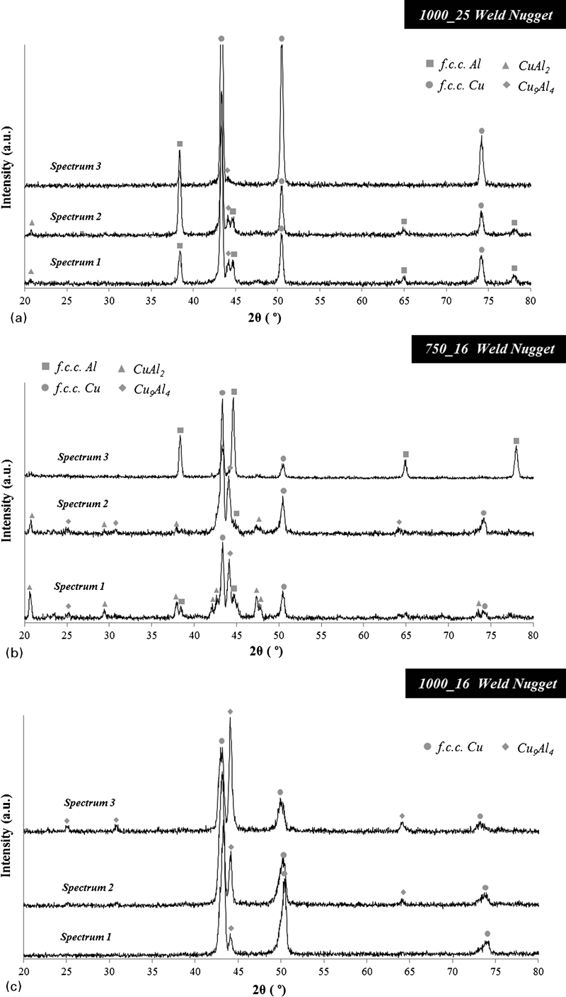
Results of XRD analysis performed in nugget of a 1000_25, b 750_16 and c 1000_16 welds
For the 750_16 weld (Fig. 3b), zones with base material composition, mixing regions with significant amounts of fcc Cu, fcc Al, Cu9Al4 and CuAl2 and mixing areas only composed of fcc Cu and Cu9Al4 were identified. This complex distribution of phases is in accordance with the heterogeneous morphology of the mixing structures already depicted in Fig. 2c. Finally, for the 1000_16 weld, which has the most homogeneous mixing area in the nugget (Fig. 2e), only fcc Cu and Cu9Al4 were detected in the nugget by XRD (Fig. 3c).
Comparing all the spectra in Fig. 3, it is possible to conclude that the composition of the nugget, similar to the nugget morphology, evolves with heat input, since increasing the ω/v ratio increases the amount of intermetallic phases and the homogeneity in composition of the nugget. In fact, whereas for the 750_16 weld both CuAl2 and Cu9Al4 were detected, for the 1000_16 weld, corresponding to the highest heat input welding conditions, only Cu9Al4 was detected.
Figure 4 shows the results of the XRD structural analysis of the silver layer on top of the welds, which is shown in Fig. 1. From the spectra, it is possible to conclude that fcc Al is the predominant phase on the top layer of all the welds. Significant amounts of CuAl2 and residual amounts of Cu9Al4 and fcc Cu are also discernible in the diffractograms. In addition to the Cu–Al system phases, the formation of minor amounts of cubic Al2O3 was also observed, which indicates that surface oxidation occurred during or after the FSW process. A BSE image and EDS spectra registered for the 1000_25 weld crown are shown in Fig. 5, where it is possible to see that the top layer of this weld has copper rich particles (Fig. 5b) embedded in an Al–Cu mixed matrix (Fig. 5c). The Al–Cu matrix consists of a mixture of CuAl2 and Al, and the Cu richer particles correspond to the Cu and/or Cu9Al4 phases detected by XRD. The same type of morphology was registered for the other two welds. Therefore, the thick and irregular surface of the welds results from the deposition of an intermetallic rich layer, with physical and mechanical properties quite different from those of both base materials. The differences in the amount of the different phases, which can be depicted by comparing the diffractograms in Fig. 4, can be attributed to the strong irregularity of the material deposition process at the top of the weld, which was already discussed when analysing Fig. 1.
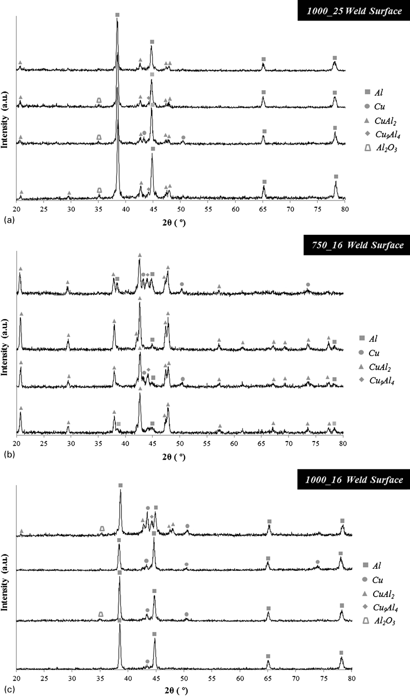
Results of XRD analysis performed on surface of a 1000_25, b 750_16 and c 1000_16 welds
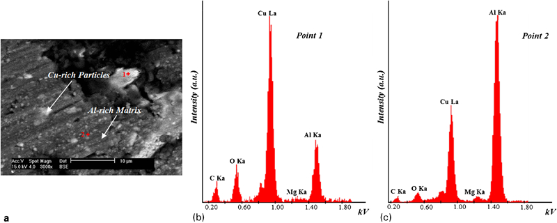
Image (BSE) registered on surface of a 1000_25 weld and EDS spectra acquired in b copper rich and c aluminium rich zones
Another important aspect to retain from previous analysis is that whereas in the nugget the structure and composition clearly evolve by changing process parameters (compare Figs. 2 and 3), at the weld surface, the structure and composition are very similar, independent of the welding conditions (compare Figs. 1 and 4). This has to be a consequence of the concurrent effect of material flow in the FSW and the mechanisms of intermetallic phase formation, as will be analysed in the next section.
Analysis of intermetallic phase formation
According to Ouyang et al., 3 the formation of intermetallic phases cannot be exclusively understood based on the Al–Cu phase diagram,15 since the chemical reactions occurring under the thermal cycles imposed by the FSW process are far from the equilibrium conditions. Furthermore, the melting temperature of the Cu9Al4 intermetallic phase (1030°C)16 is quite higher than the peak temperatures registered during Al–Cu FSW. 3 3,7 Therefore, only a thermomechanically induced solid state diffusion process can justify the formation of this high melting temperature intermetallic phase under FSW thermal conditions.
In this work, the highest amount of Cu9Al4 was detected in the 1000_16 weld nugget. Figure 6 shows the (111) and (200) fcc Cu peaks and the (330) Cu9Al4 peak of the diffractograms of Fig. 3c. In addition to the XRD patterns (in red), the results of the fitting with pseudo-Voigt functions (in blue and green) are also presented in the figure. Analysing the figure, it is possible to conclude that the (111) and (200) Cu diffraction peaks in Fig. 6a are highly asymmetrical, presenting a shoulder at lower diffraction angles. Both peaks can be fitted with two contributions, one with 2θ value corresponding to the Cu base material, and another with lower intensity and centred at lower diffraction angles, which corresponds to a solid solution of Cu(Al). Both phases are also present in the diffraction patterns of Fig. 6b and c, although the intensity of the diffraction peaks indexed to the Cu(Al) solid solution in Fig. 6c is higher than that indexed to the Cu base material. It is also important to observe that despite the fact that the relative intensities of the Cu and Cu(Al) contributions differ from figure to figure, the amounts of Cu9Al4 and Cu(Al) formed in the different zones of the nugget are closely related. Higher amounts of Cu(Al) correspond to higher amounts of Cu9Al4 and vice versa.
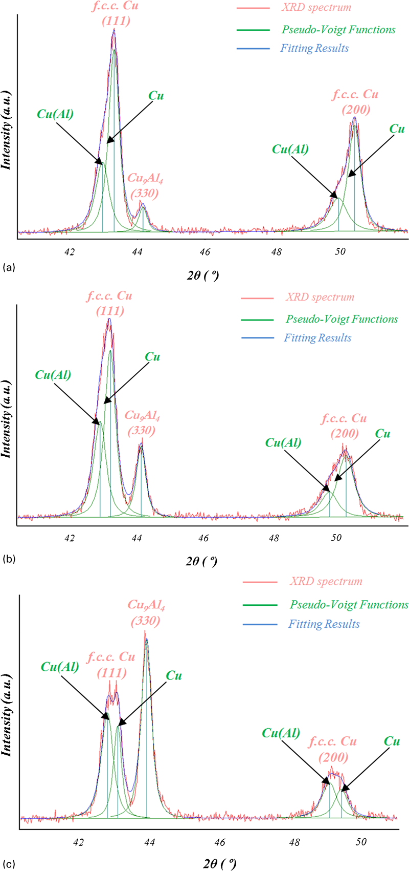
Magnification and fitting analysis of strongest Cu9Al4 and fcc Cu peaks of XRD spectra a 1, b 2 and c 3, acquired in nugget of 1000_16 weld
Since the formation of the Cu(Al) solid solution results from the incorporation of Al atoms in the Cu structure,3 it can be argued that Cu9Al4 formation follows the same mechanism. During FSW, the incorporation of Al atoms in the Cu matrix can be assumed as a mechanical process, which results from the stirring action of the tool, pushing aluminium from its retreating side and copper from its advancing side into the inner shear layer surrounding the pin. This assumption is based on the results of a deep analysis of the material flow mechanisms during dissimilar Al–Cu FSW, which can be found in Ref. 5. The shear layer materials, which complete one or more revolutions around the pin before being extruded against the retreating side at the back of the tool, are subjected to extremely intense plastic deformation, which, according to some authors, enhances the solid state diffusion rates in solid state joining processes.17– 24 Increased atomic diffusion rates enable achieving a suitable atomic concentration for Cu9Al4 formation even at low FSW temperatures. The occurrence of favourable conditions for Cu9Al4 formation, mainly at the shear layer surrounding the pin, with a copper rich composition, is the reason why this intermetallic compound was detected in large amounts when analysing the weld cross-section, but only in small amounts at the weld surface. Once again, the FSW material flow mechanisms analysed by Galvão et al. 5 are on the basis of current assumption.
Concerning the CuAl2 phase, previous studies reported that this compound has an enthalpy of formation significantly lower than the Cu9Al4. 25 25,26 Effectively, from the Al–Cu equilibrium diagram, it is possible to observe that the formation of this phase results from a peritectic reaction, which occurs at 590°C. 3 3,15 However, during FSW, the formation of this compound should also be explained based on a thermomechanically induced solid state diffusion process, since, although its melting temperature is close to the FSW temperatures, no solidification structures such as primary dendrites of Al and CuAl2 and/or Al–CuAl2 eutectic structures were detected in the SEM analysis. Nevertheless, since the temperatures achieved during FSW are close to the CuAl2 melting temperature, the formation of this intermetallic occurs wherever the suitable atomic concentrations are locally achieved, which easily occurs at the weld surface, where the shoulder drags large amounts of aluminium from the retreating side of the tool against the copper plate surface at the advancing side. This mechanism also explains the presence of large amounts of CuAl2 at all weld surface, independent of the welding parameters in use. By increasing the heat input, increasing amounts of both Al and CuAl2 will be dragged by the shoulder into the inner shear layer surrounding the pin, where chemical and thermomechanical conditions for the formation of Cu9Al4 exist. In fact, the cross-sections in Fig. 2 show that the shear layer dimensions increase with increasing heat input, while the upper aluminium layer tends to disappear.
Finally, the XRD results in Fig. 3c showed the absence of CuAl2 in the nugget of the 1000_16 weld, produced under the highest heat input conditions, which can be explained assuming the occurrence of structural evolution of the CuAl2 into Cu9Al4, inside the shear layer. In fact, an investigation conducted by Wang et al., 25 which was aimed to study the combustion synthesis of copper aluminides, reported that for copper rich mixtures, the formation of Cu9Al4 and solid solution of aluminium in copper is possible through the consumption of Cu, Al, CuAl and CuAl2. Since in the present study CuAl2 was detected on the surface of all the welds, independently of nugget phase composition, it is possible to assume that CuAl2 present at the weld surface results mainly from base material stirring under the shoulder, where large amounts of aluminium are stirred against the copper surface.5 In the course of the dynamic material flow process, the materials under the shoulder are incorporated in the shear layer surrounding the pin, 5 5,27 where material mixing and plastic deformation are extremely intense, and conditions for Cu9Al4 formation will be reached under appropriate heat input conditions.
Conclusions
The influence of the welding parameters on brittle intermetallic phase formation and distribution during aluminium to copper FSW was investigated. It was observed that increasing the heat input, by performing welds under higher ω/v ratio, resulted in the formation of mixed material zones with increasing dimension and homogeneity. The morphology of the mixing zones and the type and amount of the intermetallic phases, which were found to result from a thermomechanically induced solid state process, are also strongly dependent on the welding parameters. In fact, under lower heat input conditions, no important mixing patterns were found in the nugget, indicating the formation of an interface morphology similar to that obtained by other authors when performing friction diffusion bonding. On the other hand, increasing the ω/v ratio, the weld nuggets displayed heterogeneous phase composition, with significant amounts of both base materials (Al and Cu) as well as some quantities of CuAl2 and Cu9Al4 intermetallic phases. For the welds obtained under the higher ω/v ratio, only Cu, Cu(Al) solid solution and Cu9Al4 were registered. The structural evolution of the CuAl2 intermetallic phase, under the mechanical conditions developed inside the shear layer surrounding the pin, was pointed as one of the reasons for the formation of increasing amounts of Cu9Al4 and Cu(Al) under higher heat input conditions. Finally, it was found that the rough and irregular crowns, characteristic of dissimilar aluminium to copper friction stir welds, result from the formation of a CuAl2 rich layer under the shoulder, at the weld surface, which is irregularly distributed at the trailing side of the tool during the welding process.
Footnotes
Acknowledgements
The authors are indebted to the Portuguese Foundation for the Science and Technology (FCT) and FEDER for the financial support and to company Thyssen Portugal – Aços e Serviços Lda for providing the heat treatments for the FSW tools.