
Abstract
This study was performed to evaluate the characteristics and strengths of dissimilar joints between carbon fibre reinforced plastics (CFRP) and stainless steel using high brightness continuous wave disc laser. Tensile shear tests demonstrated that strong CFRP steel joint with ∼4800 N could be produced. The joints were tightly bonded on atomic or molecular sized level through Cr–Fe oxide film on the metal surface, and small fragments of type 304 steel were detected on the fractured CFRP. Many bubbles of submillimetre size were formed all over the plastic melted zone in the CFRP. The gas compositions inside the bubbles were H2 and hydrocarbon series as pyrolysis gases of the CFRP as well as N2 in air. These results suggest strong chemical and physical bonding of the CFRP on the oxide film of the type 304 plate. Consequently, it was confirmed that a strong joint could be produced between CFRP and type 304 stainless steel with a laser beam.
Introduction
Recently, plastic composite materials with light weight and high strength have been widely used in industrial applications, such as aircrafts, automobiles, high speed trains, etc. Among others, carbon fibre reinforced plastics (CFRPs) with the excellent characteristics of high strength/weight ratio, no corrosion and outstanding fatigue resistance are currently satisfying demands as the new advanced material in automobiles and aircrafts, where weight reduction and CO2 emission reduction are necessary. 1 1,2 Therefore, the development of manufacturing technologies, such as cutting, drilling and joining, needs to use CFRP materials in the proper positions.3– 5 Among others, joining of dissimilar materials is necessary and important for such new advanced materials in terms of their widespread applications and improvement in the production performance. 6 6,7 Joining of dissimilar metallic materials, such as steel and aluminium or magnesium alloy, stainless steel and copper, etc., has been carried out widely. 8 8,9 However, there are few trials to join dissimilar metal and CFRP. Joining of metal–plastic and metal–CFRP materials is usually conducted using adhesive bonds (glues) or mechanical tools, such as bolts and rivets. 10 10,11 However, these joining processes have several problems, such as environmental restriction of volatile organic compound emission and inconvenience of mass production caused by additional processes. Therefore, laser assisted metal and plastic direct joining (named LAMP joining in short) has been developed to rapidly produce strong joints between commercially available metals, such as steel, stainless steel and aluminium alloy, and engineering plastics, such as polyamide (PA) and polyethylene telephthalate, using continuous wave (CW) Nd∶YAG laser with a near Gaussian beam or diode laser with a line shaped beam.12– 15 These papers reported that the LAMP joining was characterised by the interaction of the flow of the melted plastic and the high pressure caused by the generation and rapid expansion of bubbles in the plastic near the joint interface, and consequently, the LAMP joint was tightly bonded by chemical and physical bonding (van der Waals forces) on the atomic or molecular level through the oxide film on the metal surface, 12 15 12,15,16 as well as mechanical bonding (anchor effect).17 On the other hand, LAMP joining of metal and CFRP with high laser beam absorptivity has not been attempted, and joining or bonding mechanisms between two materials have not been investigated.
In this research, therefore, LAMP joining was conducted to produce strong lap joints between CFRP and type 304 stainless steel with CW high brightness disc laser. The joining feasibility and strength of such dissimilar material combination were evaluated by the tensile shear test of the lap joint specimens. The fusion zones and the microstructure near the joint interface of these dissimilar materials were observed by optical microscope, scanning electron microscope (SEM) and transmission electron microscope (TEM) and analysed by SEM and energy dispersive X-ray spectrometer (SEM-EDS) to elucidate the joining mechanisms, the origin of a strong joint and the possibility of chemical bonding of CFRP to steel.
Experimental
The materials used in LAMP joining experiments are commercially available type 304 austenitic stainless steel and CFRP. The chemical composition of the type 304 steel used is Fe–18Cr–8Ni–1Mn–0·6Si–0·05C–0·026P–0·01S (mass-%). The plates used for joining were 3 mm thick, 30 mm wide and 70 mm long. The CFRP consisted of polyamide 6 as a matrix plastic and a long fibre pellet type of carbon fibres with the volume of 20%. The specimens of 3 mm thickness, 20 mm width and 100 mm length were prepared from 3 mm thick CFRP sheet of 100 mm width and 150 mm length manufactured by injection moulding. The average tensile load (and strength) of the four base CFRP specimens was ∼9000 N (and 150 MPa) in the tensile test at the travelling speed of 2 mm min−1 for the gauge length of 40 mm. Before LAMP joining, the surfaces of the metal and the CFRP sheets were cleaned with ethanol.
An experimental set-up for the LAMP joining process of a CFRP sheet to a metal plate is schematically shown in Fig. 1. Two sheets of different materials were lapped and tightly fixed by pressing two bridge plates by four bolts, each of which was equally submitted to a 60 N cm torque. The high brightness CW disc laser with maximum power of 16 kW and wavelength of 1030 nm was utilised, and a laser beam of 8 mm mrad (beam parameter product) was delivered by the optical fibre of 0·2 mm core diameter. The spot size of a laser beam was ∼0·3 mm at the focal point. A laser beam was directly irradiated on a 3 mm thick type 304 stainless steel plate overlapped on a 3 mm thick CFRP sheet with 20 mm width. The LAMP joining conditions used in the experiments were laser power of 2 kW, travelling speed of 5 mm s−1 and defocused distance of 20 mm. Ar shielding gas of 30 L min−1 was used to suppress the oxidation of molten steel surface.
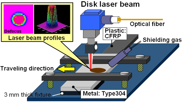
Schematic illustration of experimental set-up of type 304 stainless steel plate placed on CFRP sheet and LAMP joining process with high brightness CW disc laser and its defocused beam mode and profile
The strengths of the LAMP joints were evaluated by the tensile shear test at the travelling speed of 0·33mm s−1 (2 mm min−1) for the gauge length of ∼100mm. The microstructure of the cross-sections of the joints was observed by optical microscope and SEM to investigate the melted zones in the CFRP, the size of joining areas and the correlation between the flow of the melted plastic and the bubbles generated inside the CFRP. The gas compositions inside the bubbles were measured by a special Q-mass spectrometer. The microstructure of the joint was examined on atomic or molecular sized levels by SEM and TEM. Moreover, SEM observation and EDS analyses of the fractured surfaces were conducted to understand the production of strong joints.
Results and discussion
Strong joint of CFRP to type 304 stainless steel
The LAMP joining of CFRP to type 304 stainless steel was performed by directly irradiating a disc laser beam on the metal plate lapped on the CFRP sheet. In type 304 plate, a partial penetration weld was formed, and the absorbed input should heat up the CFRP near the interface of the lap joint. The lap joint specimens, which could not be broken by human hands, were produced. The mechanical properties of the joints were evaluated by the tensile shear test.
Figure 2 indicates the LAMP joints between CFRP sheet and type 304 stainless steel plate before and after the tensile shear test. The cross-sectional photo in Fig. 2b shows that the laser partially penetrated weld bead was made in type 304 stainless steel by a shallow keyhole, and consequently, a melted zone was widely generated inside the CFRP near the joint interface. In Fig. 2c, a certain area of black CFRP is observed to remain adhered to the bottom surface of the type 304 stainless steel plate. In particular, adhering CFRP was chiefly present under the laser irradiated part. This means that the fracture occurred mainly in the melted zone of the CFRP. In addition, part of CFRP ejected from the melted zone near the interface was apparently observed on both sides of the CFRP sheet. This is attributed to the excessive expansion of the PA matrix of CFRP.
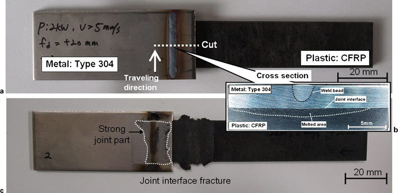
Laser assisted metal and plastic lap joint specimen between CFRP and type 304 stainless steel before and after tensile shear test
The tensile test was carried out to evaluate the joint strength. The results are shown in Fig. 3, indicating the load–elongation curve (corresponding to stress–strain curve) of a LAMP lap joint in the tensile shear test in comparison with that of the base CFRP specimen in the tensile test. The tensile shear load (strength) of the LAMP joint was ∼4800 N (for 20 mm wide CFRP), which was half higher than the tensile load of the base CFRP specimen. This load for the lap joint is regarded to be the highest among the LAMP joints between a plastic and a metal. When the load is divided by the CFRP cross-sectional area of 60 mm2, the tensile strength of 80 MPa was achieved for the joint. It is judged from the high tensile shear load and tensile strength, fracture pass in the CFRP and adhesion of the CFRP part on type 304 steel plate that strong lap joints could be obtained between CFRP and type 304 stainless steel by the LAMP joining method.
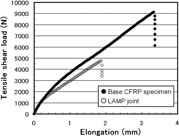
Results of load–elongation curve in tensile test of base CFRP specimen and LAMP joint between CFRP to type 304 steel
Bubble characteristics inside CFRP and joining mechanisms of LAMP joint
The tightly bonded joints between CFRP and type 304 stainless steel were investigated in detail. The SEM cross-sectional photos near the joint interface are shown in Fig. 4. Figure 4a shows that type 304 was in the solid state at the joint interface, and many bubbles of submillimetre size were irregularly generated in the CFRP matrix plastic, and especially around the carbon fibres, by heat conduction from a high temperature molten pool in type 304 steel plate during laser welding. It is seen in Fig. 4b that the melted plastic entered in grooves or grain boundaries of the type 304 steel at the joint interface, suggesting that mechanical bonding (sometimes called anchor effect) should be achieved. The formation location of bubbles in the CFRP plate was different from that in the engineering plastic without fibres since the bubbles were localised near the joint interface in the latter plastic. It is consequently regarded that the geometrical characteristics of the bubbles inside the CFRP depended on the laminated shape of the plastic and carbon fibre as well as the level of conducted heat and the length of the carbon fibres.
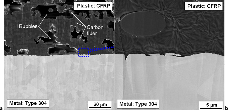
Image (SEM) of cross-section near LAMP joint interface
The TEM photo near the joint interface and the TEM-EDS analytical results are shown in Fig. 5. It is observed that the CFRP is bonded on the atomic or molecular scale on ∼10 nm thick Cr oxide (including a small amount of Fe) layer of type 304 steel. This result suggests much possibility of chemical bonding and physical (van der Waals) bonding. Therefore, CFRP and type 304 stainless steel could be bonded so tightly as to produce a strong joint.
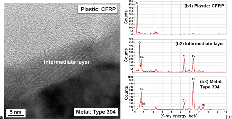
a image (TEM) of joint interface and b TEM-EDS analytical results of respective characteristic zones showing bonding CFRP to oxide film on type 304
Moreover, the gas compositions inside the bubbles were analysed with a Q-mass spectrometer by measuring the vacuum level and the mass spectra of gases emitted during drilling a hole of ∼2 mm diameter from the steel plate to the CFRP sheet under the high vacuum of 7×10⁻⁶ Pa. The results are shown in Fig. 6. It is understood that the gas components inside the bubbles consisted of N2 in air and H2 and a series of hydrocarbons as pyrolysis gases from the PA matrix of CFRP. From the above obtained results, it was confirmed that the melted plastic was directly influenced by the high pressure caused by the generation and rapid expansion of bubbles after the pyrolysis and then flowed in any grooves or grain boundaries of the metal at the interface or ejected to the outside of the CFRP specimen from the interface. It is consequently concluded that the CFRP material was directly joined by chemically or physically bonding melted plastic and oxide film on the stainless steel in addition to the mechanical anchor effect due to the plastic flowing in the pits, grooves or grain boundaries.
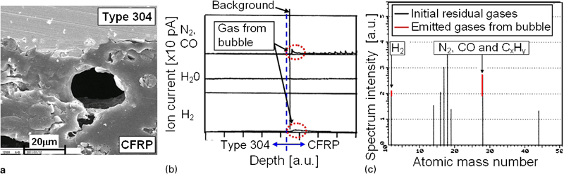
a image (SEM) of bubble observed near joint interface, b ion current (×10 pA) variation according to drilled depth showing emitted gases from bubbles in CFRP and c comparison of spectrum intensity (au) in atomic mass number between initial vacuum state and gases emitted from bubbles
In order to further confirm the strong bonding between CFRP and type 304 stainless steel, the CFRP fractured surface was also observed by SEM and analysed by SEM-EDS analysis. Figure 7 indicates the results of SEM observation and SEM–EDS analyses. It was revealed that part of the type 304 steel enriched with Cr and Fe was detected on the fractured CFRP surface through EDS point or area analyses. It is consequently confirmed that strong bonding should exist between CFRP and type 304 stainless steel from the detection of type 304 particles, including Cr and Fe elements.
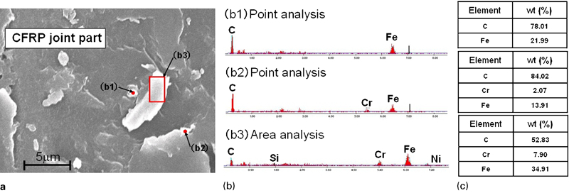
a image (SEM) of fractured CFRP surface after tensile shear test, b SEM-EDS point and area analytical results of particles on CFRP surface in a and c chemical compositions (wt-%) of representative elements of points and area analysed in b
From the above mentioned results, the LAMP joining mechanisms of dissimilar materials between CFRP and type 304 steel are interpreted by considering the schematic representation in Fig. 8. It was confirmed that many bubbles of submillimetre size were generated inside the CFRP, and the flow of the melted plastic due to the generation and rapid expansion of the bubbles inside the CFRP played an important role in directly joining the CFRP to the metal. Furthermore, it was confirmed that the strong joints between CFRP and type 304 stainless steel could be produced by forming a wide joining interface, where chemical and physical bonding of atomic or molecular sizes between melted plastic and Cr–Fe oxide film on the stainless steel surface. The bubbles were formed slightly away from the CFRP/metal joint interface probably because of the higher heat conduction effect of carbon fibres, which was different from conventional LAMP joining process between general plastic and metal. The larger number and larger sizes of bubbles led to the degradation of mechanical properties of the joint due to their actions as fracture pass sites.
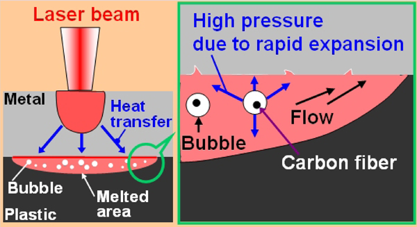
Bonding mechanism of LAMP joining process between CFRP and metal, showing generation of small bubbles inside melted PA base plastic in CFRP, flow patterns of melted plastic towards metal plate surface due to high pressure generated by rapid expansion of bubbles and tight joining of interface due to mechanical, chemical and physical bonding
Conclusions
Direct bonding of CFRP to type 304 stainless steel was carried out by LAMP joining process using high brightness CW disc laser. The tensile shear load for the LAMP joint between CFRP and type 304 was ∼4800 N, which is evaluated to be much higher than the joints of the other plastic–metal combinations. The production of a strong joint could be confirmed by the facts that a considerable amount of CFRP remained adhered to the metal surface after the tensile shear test since fracture occurred not along the interface but mainly in the melted zone of the CFRP. According to SEM and TEM observations, many bubbles of submillimetre size were generated inside the melted CFRP, inducing the flexible flow of the melted plastic, and part of type 304 enriched with Cr, Fe, etc. was detected on the fractured CFRP surface. Furthermore, CFRP and type 304 stainless steel were tightly bonded on atomic or molecular sized level through Cr(–Fe) oxide film on the stainless steel surface. It is consequently judged that the LAMP joining technology should be suitable for practical industrial applications.
Footnotes
Acknowledgements
This study was performed under the New Energy and Industrial Technology Development Organization (NEDO) Project ‘Saving Energy and Novel Technology Development Enterprise: Feasibility Research of Processing Technology of Novel Material (CFRP)’.