
Abstract
Titanium–steel composite plate finds its application to constructing large pressure vessels normally used for storage and processing petrochemicals. The present study aims to calculate the stress–strain distributions in different types of welding joints possibly used in a pressure vessel which is built with a TA2/16MnR composite plate. A finite element numerical investigation has been preformed. In this work, influences on stress–strain distributions caused by various factors such as work temperatures, working loads and joint structures, were studied, taking into consideration the welding residual stress caused by the welding process. It is found that working temperatures are the main factors that would cause a great effect on the final stress distribution. As to the different types of welding joints, the stress peaks and distributions present various patterns due to the different structures of the joints. Based on the simulation result, suitable welded joint types under different working conditions are proposed.
Keywords
Introduction
Titanium–steel composite has developed rapidly in recent years due to its low price, good corrosion resistance and the ability of withstanding higher pressure. Now, it becomes the chief structural material in titanium vessel production, where the load carrying steel base is protected against corrosive liquid environment by a clad of Ti alloy. 1 1,2 It is common practice to fabricate these vessels using fusion welding processes such as gas metal arc welding.3 However, it will bring several negative influences if the Ti alloy clad and the steel base are melted together during welding since titanium and steel are not metallurgically compatible at high temperatures that normally accompanied overlay welding.4– 7 Although some other welding methods, such as electron beam welding,8 explosive welding, 9 9,10 laser welding11 and friction welding, 12 12,13 can be used to avoid such problems, none of them is applicable in huge pressure vessel fabrication. Thus, in recent years, there had been strong interests in producing transition joints of commercial pure titanium to steel14 in order to take the advantages of ideal properties of titanium–steel composite and, simultaneously, to avoid the welding difficulties. Welding residual stress in combination with working conditions would significantly affect the dimensional precision of the structure and its usefulness and cost. 15 15,16 For welded joints of titanium–steel composite plates, it is not suitable to take post-weld heat treatment to reduce residual stress because it will cause the danger of intermetallic generation at the interface. Thus, the existence of welding residual stress should be considered in advance when pressure vessel and piping facilities are designed. Meanwhile, in the latest version of ASME VIII-2 2007, it is the first time to introduce numerical analysis method into the process of designing pressure vessels and it sets a series of rules and steps for the application of numerical analysis especially finite element method in engineering design. 17 17,18
It is of great value to get stress distributions and consider their influences together with the working conditions (temperatures and pressures) in titanium–steel composite pressure vessels. To provide basic data for designing and constructing titanium–steel composite pressure vessels, this paper adopts finite element numerical simulation technique to calculate the stress distributions of five kinds of candidate welding joints for titanium–steel composite pressure vessel under different working conditions (working temperatures and pressures).
Establishment of finite element model
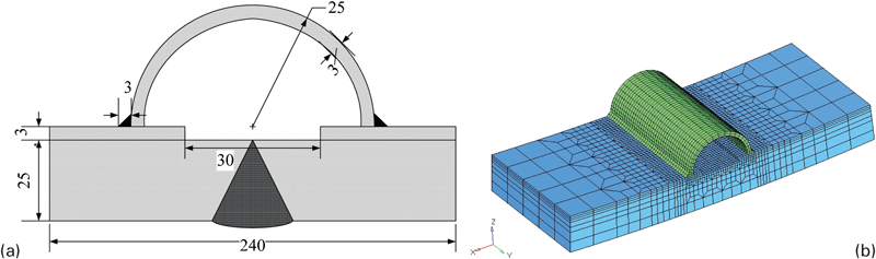
The pressure vessel with a diameter of 4000 mm is made of titanium–steel composite plate. The inside wall is formed with 3 mm TA2, which aims to prevent the outside 25 mm 16MnR wall from being corroded by the liquid inside. Five possible welding joints of titanium–steel composite are designed. One of them is shown in Fig. 1, and the others will be given later. These joints are longitudinal welds on the pressure vessel. Before welding, TA2 clad on the area of welded joints is cut away, then the base metal is welded and finally, an extra titanium alloy cover plate (the same material with composite clad) is joined to the rest of the composite clad.13 Since in practical engineering processes, welding residual stresses in the base metal can be well controlled by post-weld heat treatment, and they thus can be ignored during the computer based calculation, here, it supposes that the welding process of the base metal will impose no effects on the transition joints studied in this paper. In addition, during the welding process of these transition welds, manual argon arc welding method is used, and the processing parameters are as follows: welding current, 100–150 A; welding voltage, 15–19 V; and welding velocity, 2·5 mm s–1.
Finite element meshing
Since the whole pressure vessel is too big, here, local parts of these transition joints are cut out from the whole integrity in order to reduce the calculation time and increase the computing efficiency. Finite element models for these five joints are conducted based on the software platform of MSC.Marc, and all of them have the same dimensions of 240×100×28 mm, as shown in Fig. 1a. Tiny grid in welding joint and the area nearby is meshed, and rougher grids are used far away from the weld; a 20 node isoparametric element is adopted. An example of the finite element mesh model of the welded joints is shown in Fig. 1b. Before calculation, the dependent material properties of TA2 and 16MnR should be collected. Here, we refer to the Chinese standard JB/T 4745-2002 and GB713-2008 in which the material properties of titanium TA2 and steel 16MnR (called steel Q345R in standard GB713-2008) are listed.
Welding residual stresses of five kinds of welded joints
Since the final stress field is the combination of stresses induced by working temperatures and pressure loads, the foremost task is to calculate the welding residual stress fields for each of the five types of welding joints. Double ellipsoidal model is adopted as the welding heat source model, and dynamic transient analysis is performed. The mechanical boundary conditions mainly include displacement constraints and rotating constraints both in the circumferential and axial direction, which will ensure that no unitary displacement happens. Since the angles between the four end faces of the small joint (generated in the process of small local joints truncation) should stay the same after the pressure vessel's transformation, as shown in Fig. 2a, boundary conditions that will ensure this invariability are then carried out, as shown in Fig. 2b and c. The calculated residual stresses are shown in Fig. 3.
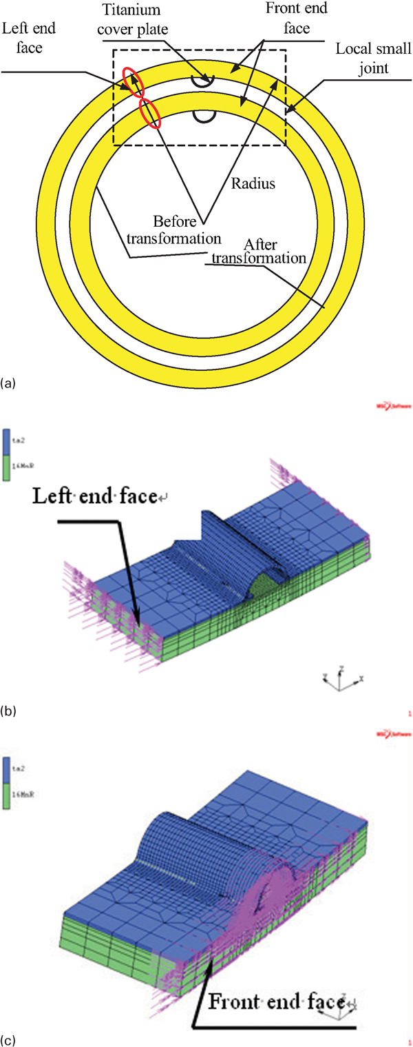
Boundary conditions for end effects
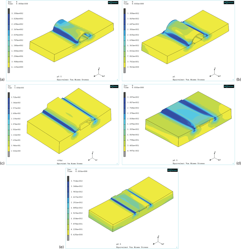
Welding residual stress distribution of five types of joints
It can be figured out from Fig. 3 that the peak value of residual stress is almost equal to the yield stress of TA2, which is about 375 MPa. This is consistent with the welding theory that the welding residual stress of titanium alloys would come up to 70% or more of their yield strength. In addition, the residual stress levels of joint Nos. 1, 2 and 4 are higher than those of joint Nos. 3 and 5, while the stress concentrations of the latter group are more serious than the former.
Stress fields of welded joints under working conditions with welding residual stress ignored
Influences of temperature on stress distributions
Stress distributions of five kinds of joints are calculated with working temperature varying from 150 to 350°C. In the calculation, five temperatures are chosen: 150, 200, 250, 300 and 350°C. Figure 4 shows the influence of temperatures on the distribution of stresses of joint No. 1, and the others are omitted due to the page limit of the paper.
Distribution of equivalent stress and circumferential stress under different temperatures
From Fig. 4, we can see that as the working temperature increases, the equivalent stress of the inside part of titanium–steel composite (the titanium side) also increases. However, when the working temperature rises up to 300 or 350°C, this increasing trend of the equivalent stress reverses, which means it begins to decrease. It is mainly because that when working temperature comes up to 300°C or more, stress caused by temperature change has reached the yield strength of TA2, which is relatively low at high temperatures. Consequently, stress caused by temperature decreases, as it has been known that metal materials yield strength will decrease as temperature rises.
Owing to the difference between thermal expansion coefficient of steel and titanium, stress produced by temperature is different. In the steel (lower side), as its thermal expansion coefficient is bigger than that of the titanium, temperature stress thereby is larger than titanium (upper side). Owing to the difference of stress induced by temperature, the steel side ultimately is loaded with compressive stress while the titanium side is the opposite. As is shown in Fig. 4f, the grey part presents the tensile stress, and the other colourful part presents the compressive stress.
Influence of pressures on stress distributions
The pressure under which the vessel works ranges from 0·5 to 10·0 MPa. As shown in Fig. 5, six different pressures are chosen from this scope: 0·5, 1·0, 2·0, 4·0, 5·0 and 6·0 MPa.
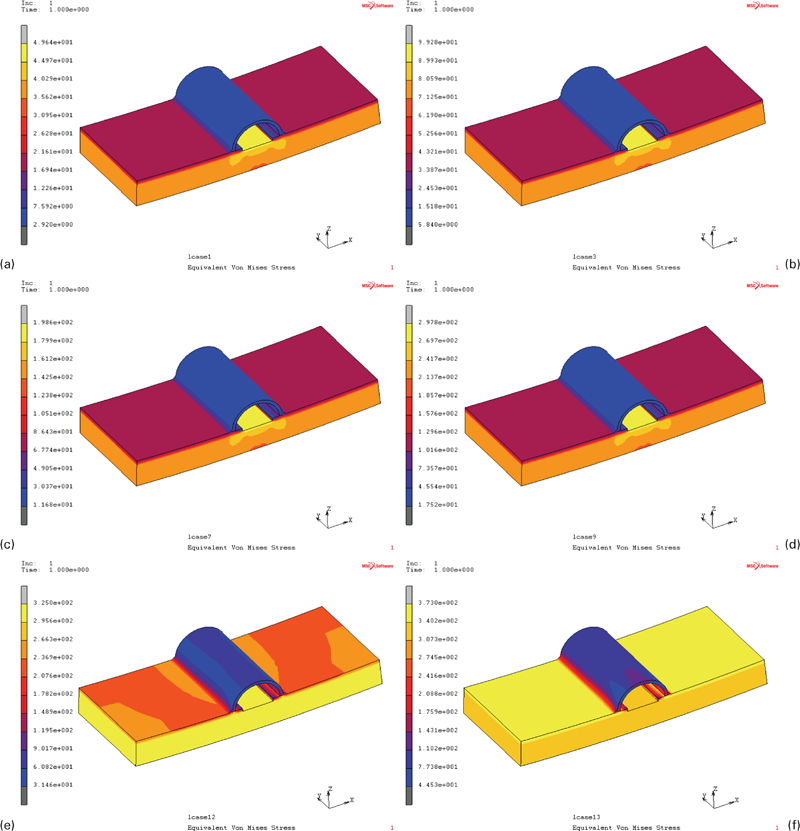
Distribution of equivalent stress under different pressures
We can see that as the pressure increases, the equivalent stress on the titanium plate also increases, and the largest stress is located at the composite gaps rather than the weld seam. When the work pressure ascends up to 4·0 MPa and above, the stress in steel side of the titanium–steel composite reaches the steel yield strength of 325 MPa, and when work pressure rises up to 6·0 MPa and above, the stress in titanium side comes to its yield strength of 373 MPa. At this point, the whole composite is yielding.
Influence of joint types on stress distributions under same working temperature
Owing to the different joint structures, there presents different stress distributions in five kinds of welded joints when working under the same temperature. Figure 6 shows the stress distributions curves along the top surface and transverse of the weld, as indicated in Fig. 6a.
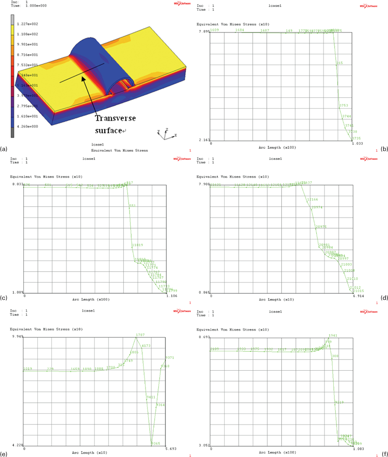
Stress distribution along surface transverses of weld line
For welded joint nos. 1–3, the turning point is located on the weld toe and its stress is the biggest. In addition, it does not produce much stress concentration on the weld and the stress in the other parts of the titanium cover plate is much smaller than that of the weld. However, for welded joint nos. 4 and 5, there are obvious stress concentrations located on the weld toe, and the peak values are also bigger than that in joint no. 1. This is because the tensile stress induced by temperature and the difference of thermal expansion coefficient of steel and titanium can be mitigated by the cambered structure in joint nos. 1–3. From this point of view, it is better to adopt joint nos. 1–3 if the pressure vessel will be running at high temperatures.
From the analysis above, it is suitable to divide these five types of welded joints into two groups: one with cambered structure, which includes joint nos. 1–3, and the other group without such structure, which includes joint nos. 4 and 5. Table 1 shows the peak stress value of typical joint types from these two groups (nos. 1 and 4), while they are loaded with different pressures, and the peak values in the joints are located at the gap where the titanium clad is cut away.
Peak stress value of typical joints under pressure load
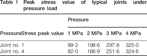
Table 1 indicates that under the same pressure, the peak stress value of joint no. 1 is larger than that of joint no. 4, and the difference becomes even bigger as pressure load increases. Thus, it is the best choice if this pressure vessel will be running under low temperature, which also means that stress induced by the inside pressure dominates the total stress value.
Stress field of welded joint under working conditions with welding residual stress considered
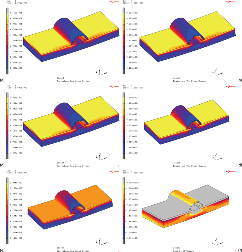
In order to make the simulation more corresponsive to the practical condition, residual welding stress should be taken into account. Figure 7 shows the stress field of joint no. 1 under the temperature of 150°C, and pressures ranged from 0·5 to 4·0 MPa. In this figure, areas that are in grey are yield areas in titanium clad.
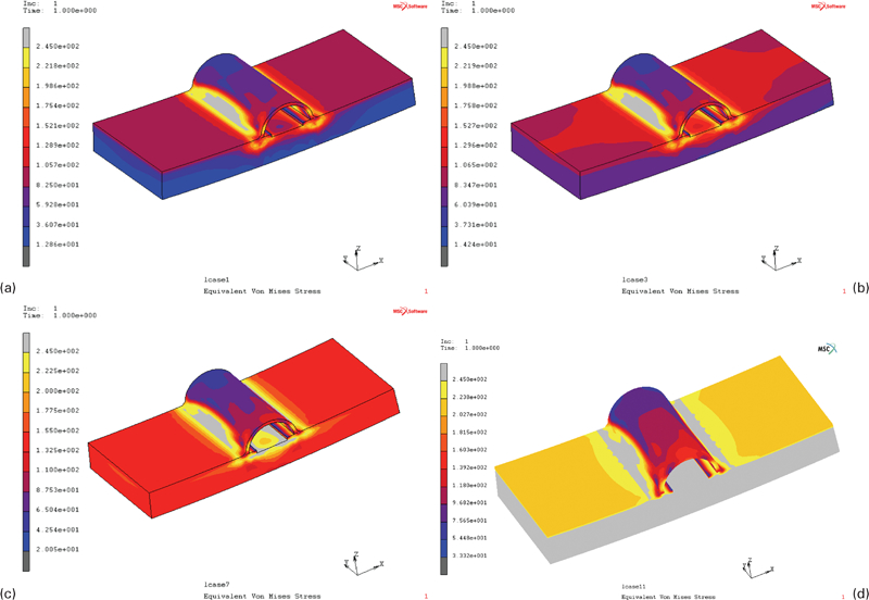
Yield areas in titanium clad under different pressures
From Fig. 7, it can be drawn that there are stress concentrations on the weld. Since the yield strength of titanium is lower than that of steel under the same temperature of 150°C, titanium yields before steel does, even if the pressure loading is only 0·5 MPa. In addition, the yield area becomes larger as the pressure increases, and it is mainly located on the weld and the titanium clad nearby.
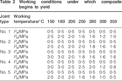
The loads under which local areas of the joints begin to yield are listed in Table 2. In this table, Pa is the stress under which the titanium clad of the composite begins to yield, while Pb is the stress under which the steel base begins to yield. From Table 2, it can be drawn that joint nos. 2 and 3 are better when the pressure vessel is working under high temperature, such as 300°C, while joint no. 4 is better when it is working under high pressure.
Working conditions under which composite begins to yield
Welding residual stress reduces the loading capability of the composite. Titanium clad near the weld begins to yield even under the lowest working load. This conclusion also implies that welding residual stress has significant negative effect on the bearing capability of local areas which contain welded joints, and these effects should be seriously considered in pressure vessel design, and it is suggested to be covered in Chinese pressure design codes as ASME code does.
Conclusions
Based on the calculation results and analysis above, conclusions can be drawn as follows.
Owing to the fact that the thermal expansion coefficient of steel is larger than that of titanium, when working temperature increases, large tensile stress on the titanium side of the composite will be generated. However, working temperature does not cause stress concentration in weld seam.
As working pressure increases, equivalent stress on titanium–steel composite will increase. However, the biggest stress is located at composite gaps rather than at the weld seam. In other words, change of working pressure will not produce stress concentration in the weld seam.
Welding residual stress has significant impact on the final stress distribution of the weld joint. Titanium clad begins to yield even under the lowest working pressure. Strength check criterion that is used in design by rules seems no longer suitable in the process of design by analysis.
It is better to adopt joint no. 4 when the working temperature is low, and joint nos. 2 or 3 when the working temperature is relatively high.
Footnotes
Acknowledgements
This research is supported by the National Science Foundation of China (grant no. 50904038).