
Abstract
In this study, welding distortion in a large thin plate panel structure was predicted by means of elastic finite element method based on inherent strain theory and interface element formulation. The welding distortions in the thin plate model computed by large deformation theory and small deformation theory were compared. The comparison suggests that the geometrical non-linearity should be carefully considered when welding distortion in a thin plate structure is predicted. In addition, the influences of welding procedure and assembly sequence on the final distortion were examined numerically. Simulation results indicate that both welding procedure and assembly sequence significantly affect the final deformation.
Introduction
The fusion welding process is widely used in shipbuilding and automobile industries to join thin plate panel structures. In recent years, high tensile strength steel thin plate has been used to replace low carbon steel for reducing weight. However, the buckling propensity induced by the welding process will increase when the thickness of the plate decreases. Buckling distortion often not only results in loss of structural integrity and dimensional accuracy but also increases fabrication cost due to correction work. For thin plate panel structures, if welding distortion and buckling propensity can be quantitatively predicted beforehand, then the predictions will be useful and helpful to improve the manufacturing accuracy.
In the past decades, a number of finite element models and experimental methods were proposed to study welding distortion in thin plate structures. Watanabe and Satoh1 investigated welding deformation in thin plates due to bead on welding. Nomoto and hisco-workers 2 2,3 studied the parameters controlling buckling distortion using both experimental and numerical methods. Tsai et al. 4 studied the bifurcation phenomenon in thin plate joint using thermoelastic–plastic, large deformation analysis and experiments. Bhide et al. 5 compared the buckling propensity for submerged arc welding, gas metal arc welding and friction stir welding using butt joints. Huang et al. 6 6,7 have developed fabrication and engineering technologies for lightweight ship structure. In their researches, some significant progresses have been achieved to control welding distortion, especially buckling distortion. Deo and Michaleris8 studied how to mitigate buckling distortion induced by welding using transient thermal tensioning.
Although the above researchers had given large contributions to control buckling distortion induced by welding, their research objects almost were limited to the laboratory specimen. Welding distortion and buckling propensity in large structures are required to do further research. In addition, investigation is needed to incorporate tack welding and welding sequence in computational approaches.9
The authors developed an elastic finite element method (FEM) based on inherent strain theory to estimate the welding distortion for large structures.10 The twisting distortion in a curved plate structure was also predicted by the developed elastic FEM.11 Through introducing the interface elements into the elastic FEM, the influences of initial gap on the final welding deformation were discussed.12
Continuing our previous researches, we have made some improvements on the interface element used in the elastic FEM and made the developed numerical method more practical for engineering analysis. In the current study, the welding distortion in a large thin plate panel structure was predicted by means of the improved elastic FEM, and the welding distortions in the thin plate model computed by large deformation theory and small deformation theory were compared. Meanwhile, the formations of gap and misalignment during assembly process were simulated in detail. In addition, the influences of welding procedure and assembly sequence on the final distortion were examined numerically.
Concepts of inherent strain and inherent deformation
During the welding process, the mechanical behaviour is very complicated.
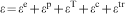
Generally, the total strain ϵ can be decomposed into
elastic strain ϵe, plastic strain ϵp,
thermal strain ϵT, creep strain ϵc
and that produced through phase transformation ϵfr

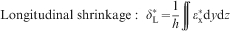
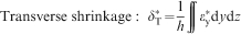
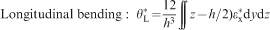
Welding deformations in a thin plate such as transverse shrinkage, longitudinal
shrinkage and angular distortion are mostly produced by the longitudinal and
the transverse inherent strains
 and
and
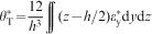
 . By integrating the inherent strain over
the cross-section normal to the welding line and taking the average value
through the thickness h, the inherent deformations are obtained13
. By integrating the inherent strain over
the cross-section normal to the welding line and taking the average value
through the thickness h, the inherent deformations are obtained13

The inherent deformations can be obtained through thermal elastic plastic finite element analysis and experimental method.10 When the inherent deformations of each joint in a welded structure are known, the overall welding distortion can be calculated using the elastic FEM based on inherent strain theory.
Elastic FEM based on inherent strain and interface element
Inherent strain method
In the developed elastic FEM, four-node shell elements (ordinary elements)
are used to model every part in a welded structure. In the ordinary elements,
the Mindlin plate theory is employed. Meanwhile, the geometrical non-linear
effect is also considered in the shell element. Figure
1 shows a thin rectangular plate and its coordinate system. With considering
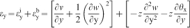
transverse shear strain effect, the total strain of each component can be
expressed using the following equations
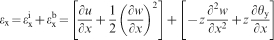


 ,
,
 and
and
 are
in-plane strains;
are
in-plane strains;
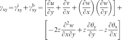
 ,
,
 and
and
 are bending strains; and γxz
and γy,z, are transverse shear strains.
are bending strains; and γxz
and γy,z, are transverse shear strains.
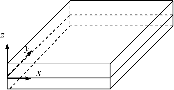
Rectangular plate and its coordinate system
The curvature κx in a plane parallel to
the x–z plane, the curvature κy
in a plane parallel to the y–z plane
and the twisting curvature κxy, representing
the warping of the x–y plane, can
be defined as follows16


 in the
longitudinal direction, while transverse shrinkage can be changed into an
in-plane strain component
in the
longitudinal direction, while transverse shrinkage can be changed into an
in-plane strain component
 in the
transverse direction. In a similar way, longitudinal bending and angular distortion
can be converted into curvatures
in the
transverse direction. In a similar way, longitudinal bending and angular distortion
can be converted into curvatures
 and
and
 respectively. In many cases, because the
longitudinal bending is very small, it is often neglected. Figure 2 schematically shows an example on
how to introduce inherent strains into the area around the welding line in
a fillet joint. It is assumed that each inherent strain component along the
welding line has uniform distribution.
respectively. In many cases, because the
longitudinal bending is very small, it is often neglected. Figure 2 schematically shows an example on
how to introduce inherent strains into the area around the welding line in
a fillet joint. It is assumed that each inherent strain component along the
welding line has uniform distribution.
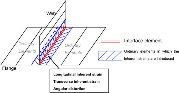
Elements with inherent deformations and agreement of interface elements in T joint
Features and functions of interface element
When the fusion welding method is used to assemble a large structure, the entire assembly process can be regarded as sequentially positioning new parts onto a reference part and joining them. Physically, the contact relationships between two parts are free before positioning. When the two parts are positioned, the distance between them is pulled to a level within a tolerable limit. In addition, the gap and the misalignment due to the initial geometrical error or induced by sequential welding can also be corrected in the course of positioning process. Hence, a relatively tight contact relationship between them is formed after positioning. After welding, a very strong bonding between the parts is generated. In order to model the real assembly process, the change of physical status must be carefully taken into account. In particular, the positioning process must be modelled cautiously with considering contact, slide and gap between parts. For this purpose, the interface element 12 12,17 is introduced in the elastic FEM. Furthermore, the interface element can describe the change of stiffness during the assembly process. Hence, besides modelling the generation of gap and its correction, the interface element can also simulate how the welding sequence affects the final distortion.
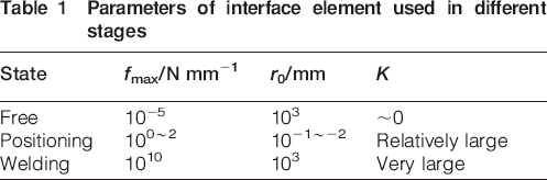
The interface element is nothing but a non-linear spring with special properties and inserted between members, as shown in Fig. 3. The relative displacements or the discontinuities of deformation across the interface element in the welding direction, in the normal direction and in the transverse direction are denoted as uL, uN and uT. The rotation around the welding direction is denoted by uθ. The forces or moments associated with these displacements are denoted by fL, fN, fT and fθ. The relations between the displacements and the forces are illustrated in Fig. 4. The mechanical properties of the non-linear spring are controlled by the stiffness K, the maximum force fmax and the gap uG. When the members are free, K = 0. In the fitting stage, the value of stiffness K for each direction is set to appropriate value according to the type of tack welding or the fixture. The gap in the fitting stage can be controlled by the values of K and fmax. As shown in Fig. 4, K is the slope of the straight line that describes the force–displacement relationship of the interface element, and it is determined by parameter fmax and scale parameter r0. In the interface elements, scale parameter r0 mainly dominates the positioning accuracy. Hence, during the positioning process, through adjusting fmax and r0, an appropriate value of K can be obtained. When the joint is fully connected after welding, the stiffness is set to be a large enough value. Table 1 shows the recommended values of the parameters used in interface elements at different stages.
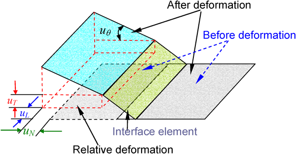
Definition of displacement in interface element
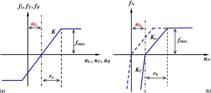
Mechanical properties of interface element
Parameters of interface element used in different stages
During the assembly process, the interface element has two main functions. One is that it can model the formations of gap and misalignment, and the other is that it can simulate the change of stiffness with welding proceeding. The latter function is very important when simulating buckling distortion during the assembly process.
Computational approach
For a large welded structure, after obtaining the inherent deformations of each joint and determining the parameters of interface elements during the assembly process, we can use the proposed elastic FEM to estimate the overall welding distortion. The computational approach based on inherent strain theory and interface element formulation is schematically shown in Fig. 5.
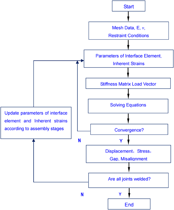
Computational approach of elastic FEM
Predicting welding distortion in thin plate panel structure
Thin plate panel structure
To investigate the features of welding deformation using inherent strain and interface element, a finite element model with large dimensions shown in Fig. 6 was developed in the current work. The material of this thin plate panel structure is assumed to be thermomechanical control process steel with 570 MPa tensile strength. The length of the skin plate is 12 000 mm, the width is 4000 mm and the thickness is 5 mm. There are three longitudinal stiffeners with 1000 mm span and four transverse stiffeners with 3000 mm span in the model. The height of transverse stiffeners is 300 mm, and that of longitudinal stiffeners is 125 mm.
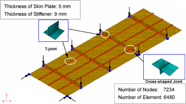
Finite element model, typical joints and restraint conditions
From Fig. 6, we can know that there are two typical joints. One is the fillet joint between the longitudinal (or transverse) stiffeners and the skin plate, and the other is the cross-shaped joint between longitudinal and transverse stiffeners. Here, it should be stressed that because the thickness of both longitudinal and transverse stiffeners is 9 mm, even though the height of the longitudinal stiffeners is smaller than that of the transverse stiffeners, we can just use one typical joint to represent the two fillet joints between the stiffeners and the skin plate. All the welding lines are donated by a solid line. There are two weld passes in each fillet joint and four passes in each cross-shaped joint. The interface elements are arranged along each welding line between two parts to be welded. Before welding, it was assumed that there were no geometrical errors in all parts. In other words, there were no initial gaps in the finite element model.
Because the thickness of the skin plate is only 5 mm, it can be inferred that buckling distortion will potentially occur after welding. To prevent too large distortion, relatively strong restraint conditions were applied to the finite element model. In Fig. 6, the restraint conditions are denoted by black arrows.
Welding conditions and inherent deformations
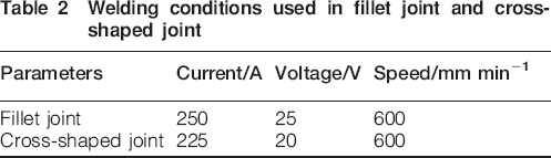
In this study, to clarify the influence of welding procedure on the final distortion, it was assumed that the fillet joints were performed by two methods. One is double sided welding, and the other is single sided welding. CO2 gas arc metal welding was assumed to perform the welding, and the welding parameters for each side are given in Table 2. Single sided welding was assumed to perform the cross-shaped joints, and the welding conditions for each weld pass are also shown in Table 2. The efficiency was assumed to be 0·85.18
Welding conditions used in fillet joint and cross-shaped joint
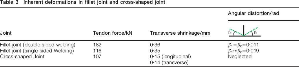
Using thermoelastic–plastic FEM, the inherent deformations of each joint can be estimated. The finite element models of two typical joints are schematically shown in Fig. 5. The detailed computational approach can be found in Refs. 10 and 19, so we only report the simulation results in the current paper. The inherent deformations of the fillet and cross-shaped joints are shown in Table 3. Three inherent deformation components of the fillet joint are used to predict the total welding distortion in the whole structure, and the longitudinal bending was neglected because of the insignificant value. Because the out of plane deformations are very small in the cross-shaped joint, only the in-plane inherent deformations (tendon force and transverse shrinkage) were selected to simulate the overall welding distortion of the large model. The approach to transfer the inherent deformations into inherent strains can be found in Refs. 10 and 12.
Inherent deformations in fillet joint and cross-shaped joint
It should be stressed that the influence of residual stress and distortion built up in the previous welds on the inherent deformation was not considered in the present study.
Simulation cases
In the current study, four simulation cases were conducted. The detailed information of each case is summarised in Table 4. In this study, cases A and A′ are used to distinguish the simulation results computed by large deformation theory and small deformation theory. Through comparing cases A and B, the influence of the welding procedure (double sided welding/single sided welding) on the final distortion will be clarified. Cases B and C are used to examine the influence of assembly sequence on the final distortion.
Simulation cases
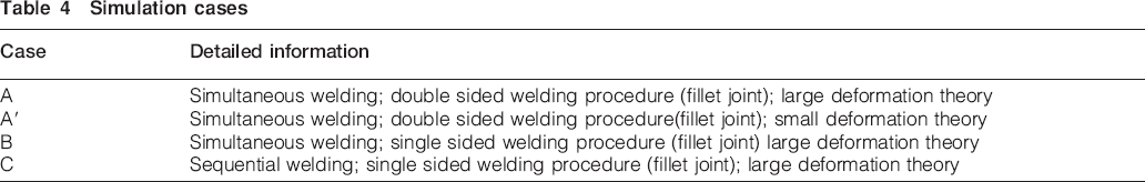
In cases A, A′ and B, it was assumed that all the welding lines were welded at the same time. In these three cases, the parameters of interface element have large values, and the stiffness of interface elements is very strong. In case C, it was assumed that the large structure was assembled by four steps. At the first step, the three longitudinal stiffeners and the skin plate were welded simultaneously. At the second step, the gaps between the transverse stiffeners and the skin plate were corrected through adjusting the parameters of interface elements. At the third step, four transverse stiffeners and the skin plate were joined simultaneously. At the final step, all cross-shaped joints between the longitudinal stiffeners and the transverse stiffeners were welded at the same time.
Results and discussion
Comparison between large deformation theory and small deformation theory
Figure 7 compares the deflection distributions along line 1 between cases A and A′. It is clear that the deflections calculated by large deformation theory (case A) are significantly larger than those computed by small deformation theory (case A′). From Fig. 7, it can be seen that the deflection distribution of case A′ has a symmetric shape. However, the shape of deflection distribution of case A is significantly asymmetric, especially near the two ends. This information suggests that buckling distortion occurred in case A. Figure 8 shows the longitudinal shrinkage distributions of skin plate predicted by cases A and A′. The magnitudes of longitudinal shrinkage are the differences between the x displacements along line 2 and those along line 3. The distribution shape of longitudinal shrinkage predicted by case A is similar to that calculated by case A′, but the magnitudes of the former are larger than that of the latter. Figure 8 also tells that the maximum shrinkage happened at locations with longitudinal stiffener because these locations are the weld zones.
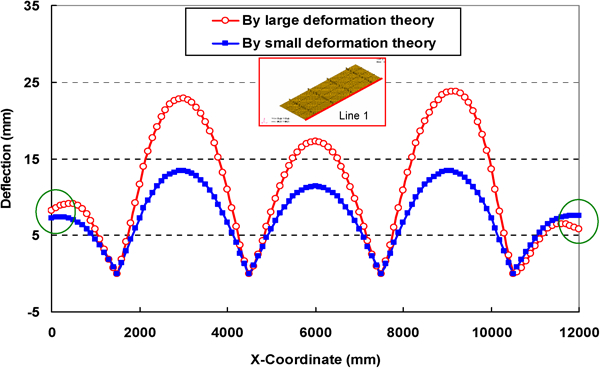
Comparison of deflection along line 1 between cases A and A′
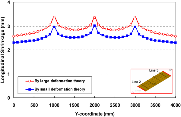
Comparison of longitudinal shrinkage between cases A and A′
Through comparing cases A and A′, we can conclude that the geometrical non-linearity should be considered when we predict welding distortion in thin plate large structures. In such case, if small deformation theory is used, then it will significantly underestimate the welding distortion.
Influence of welding procedure on final distortion
Figure 9 shows the contours of deflection distribution predicted by cases A and B. The fillet joints in case A were performed by double sided welding procedure, while the corresponding joints in case B were joined by single sided welding procedure. Table 3 shows that even though the total heat input used in the fillet joint is not changed, however, the different welding procedure can result in different inherent deformations. For the present fillet joint, the double sided welding procedure produced a larger tendon force and a smaller angular distortion. Because of the different inherent deformation, the final deflection distribution of case A is significantly different from that of case B in both magnitude and shape, as shown in Fig. 9.
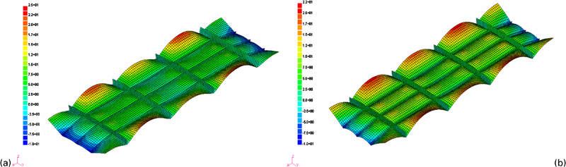
Deflection distributions after welding
Figure 10 shows the deflection distributions along line 1. Within the ranges near two ends, not only the magnitudes of deflection predicted by case B are significantly larger than those simulated by case A but also the deflection distribution shapes of the two cases are different. Here, we pay attention to deflection distributions within the range from x = 0 mm to x = 1500 mm. Figure 10 shows that the deflections monotonously decrease within this range in case B, while the deflection increases within the range from x = 0 mm to x = 400 mm and then decrease in case A. From Fig. 10, we can also find that the magnitudes of deflection near the left end are larger than those near the right ends. This information clearly indicates that buckling distortion occurred in case A. The larger tendon force induced by the double sided welding producer is the reason resulting in buckling distortion in case A.
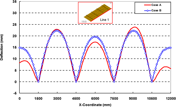
Deflection distributions along line 1 predicted by cases A and B
Within the range between x = 1500 mm and x = 4500 mm, we can see that the deflections of case A are almost the same as those of case B, but only the maximum value is a bit larger than that of case B. Within the range between x = 7500 mm and x = 10500 mm, we can see that the deflections of case A are slightly larger than those of case B on the whole, and the peak value of case A is clearly larger than that of case B. Although the angular distortion of fillet joint in case A is smaller than that in case B, the tendon force is significantly larger than that in case B. In principle, tendon force (or longitudinal shrinkage) is the most important factor resulting in longitudinal bending and buckling distortion. In a welded structure, the total out-of-plane deformation is commonly determined by the longitudinal bending resulting from tendon force and the deflection caused by angular distortion. Based on the above discussion, it is not difficult to understand that even though the inherent deformations in these two cases are markedly different, the final deflections within the above two ranges have no significant difference.
Within the range between x = 4500 mm and x = 7500 mm, the deflections of case A are lower than those of case B. The local restraint intensity of this range is larger than that of the other range, so the longitudinal bending caused by tendon fore is restrained to some extent. In such a situation, the angular distortion seems to have a larger contribution to the magnitude of deflection.
Comparing cases A and B, we can also find that the deflection distribution along line 1 predicted by case B has a symmetrical shape, but that predicted by case A is asymmetric. The simulation results suggest that welding procedure has a significant influence on the final welding deformation.
Influence of assembly sequence on final distortion
In this section, we will discuss the influence of assembly sequence on the final distortion. First, we examine the welding deformations produced during the assembly process in case C. Figure 11 shows the contours of deflection distributions after all the assembly steps in case C. It is clear that very large deflections were produced after the first welding because of the relatively small stiffness and the large angular distortion. From Fig. 11a, we can see that there are large gaps between the transverse stiffeners and the skin plate, and we can also infer that the maximum gap is over 80 mm. In such a situation, if the gaps are not corrected, then it will be impossible to perform the rest welding lines. After correcting the gaps, the deflection distribution sharply changed, as shown in Fig. 11b. Comparing Fig. 11a and b, we can find that gap correction can largely reduce the magnitude of welding deformation. After welding the transverse stiffeners and the skin plate, the deflection distribution changed to some extent in both magnitude and distribution shape, as shown in Fig. 11c. Figure 11d shows the deflection distribution after the final welding. The final welding seems to have no significant contribution on the total deflection, so we can see that the difference between Fig. 11c and d is very small.
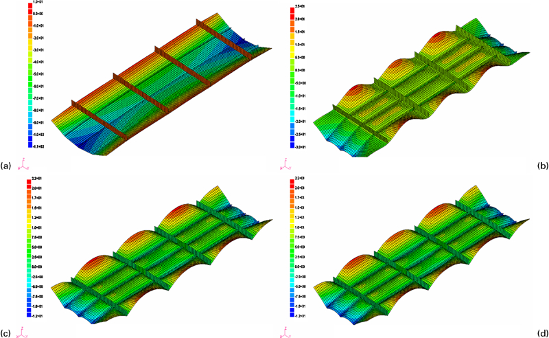
Deflection distribution changes during assembly process
The deflection distributions along line 4 after each assembly step are plotted in Fig. 12. Line 4 is the centreline of the skin plate, and it is located at the place of the middle longitudinal stiffener. This figure clearly shows the changes of deflection distribution during the entire assembly process. The change tendency is similar to that reflected in Fig. 10.
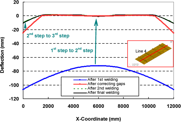
Deflection distributions along line 4 after each assembly step
Through comparing cases B and C, we can examine the influence of assembly sequence on the final distortion. The deflection distributions along lines 2 and 4 are plotted in Figure 13 Figs. 13 and 14 respectively. The deflection distributions along the two compared lines predicted by the two cases have similar shape, but the magnitudes of welding distortion in case C are larger than those in case B on the whole. Because all parts were welded at the same time in case B, the stiffness was a constant during welding, and its value was relatively large. In addition, there was no any gap between parts in this case. On the contrary, the stiffness in case C changed (increased) with assembly proceeding, and it was relatively small at the first assembly step. Moreover, large gaps between the transverse stiffeners and the skin plate were generated after the first welding. Even though the gaps were corrected to a certain extent at the second step, they were not completely closed. Considering the above factors, it is easy to understand that the magnitude of welding deformation in case C is larger than that in case B.
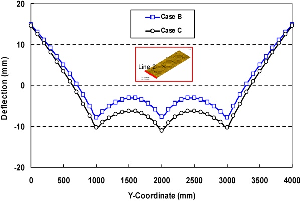
Deflection distribution along line 2 predicted by cases B and C
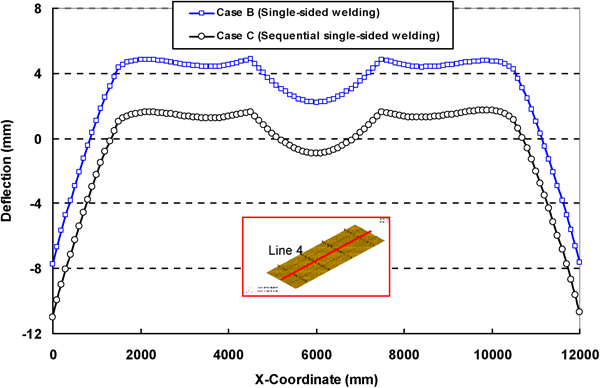
Deflection distribution along line 4 predicted by cases B and C
The comparison between cases B and C indicates that the assembly sequence has a relatively large influence on the final welding distortion.
Conclusions
The welding distortion in a large thin plate panel structure was predicted by means of elastic FEM based on inherent strain theory and interface element formulation. The influence of welding procedure on the final distortion was clarified numerically. In addition, the influence of assembly sequence on the final welding distortion was investigated. Based on the simulation results, the following conclusions can be drawn.
Because the stiffness of a thin plate welded structure is relatively small, geometrical non-linearity is apt to occur during the assembly process. When the elastic FEM is used to predict welding deformation in a thin plate structure, large deformation theory should be involved in the elastic FEM.
The simulation results suggest that welding procedure has a certain influence on the final welding distortion. Double sided welding procedure can produce a larger tendon force, so it can increase the buckling propensity, especially in thin plate structures.
Based on the simulation results, we have known that the assembly sequence has a significant influence on the final distortion. The present work suggests that sequential welding will increase the welding distortion.
The proposed elastic FEM not only may be used to estimate the welding deformation of a large and complex structure in the design stage but also can be employed to optimise the welding procedure during the manufacturing stage.