
Abstract
The feasibility of friction stir welding for joining AA 1100 based metal matrix composites reinforced with B4C particulate is studied for 16 and 30%B4C volume concentrations. For both composites, friction stir welding has a significant influence on the particle size distribution and the matrix grain size. For the 16% composite, the average particle size decreases after welding by ∼20% and the grain size from 15 to 5 μm as measured in the weld nugget. Tensile testing of welded joints showed up to 100% joint efficiency for both annealed AA 1100–16%B4C and AA 1100–30%B4C composite materials. However, if the ultimate tensile strength values of all the studied composites are similar at ∼130 MPa, then the weld ductility is higher for the annealed materials. Furthermore, it was observed that varying the welding speed between 100 and 275 mm min−1 does not influence the tensile properties and the particle size distribution in the nugget.
Keywords
Introduction
The welding of different components has become a necessity for an increased number of Al based metal matrix composite (MMC) applications, as more complex structures are being designed continuously. However, the welding of MMCs is always a challenge. Fusion welding techniques have yielded some success, but problems such as reinforcement segregation, porosity and chemical reactions can readily arise with this welding practice. 1 1,2 Compared with fusion welding techniques, friction stir welding (FSW) shows tremendous advantages, as it eliminates the main typical defects induced by fusion welding. 3 3,4
Previous works have demonstrated that sound friction stir welds without visible defects can be achieved for aluminium based MMCs reinforced with up to 25 vol.-% ceramic particles.4– 8 It is also worth noting that FSW could lead to more uniform particle distribution if any cluster or regular orientation of particles was present in the base material (BM).5– 7 The breakage of ceramic particles was also noted in some investigations. 4 4,8 However, no significant fragmentation of B4C particles was detected in welds in 6 or 10·5 vol.-%B4C composites.5 Concerning the mechanical properties of FSW joints of Al based MMCs, previous works report tensile strengths in the as welded condition as high as 60–84% efficiency. 4 5 4,5,8 An appropriate post-weld artificial aging treatment can further increase this efficiency up to 93% of the parent metal strength.5 However, the elongation of these FSW joints exhibited a significant decrease, which cannot be recovered through post-weld heat treatment.
Al–B4C MMCs have been mainly used in nuclear spent fuel storage and transportation applications owing to their good mechanical properties, stability at elevated temperatures and specific capability of capturing neutrons. 9 9,10 Our previous work focused on the FSW of AA 6063–B4C MMCs, which represents heat treatable materials for structural use.5 The present study is intended to evaluate the feasibility of FSW for joining AA 1100–B4C MMC, which is a non-heat treatable material. The microstructural evolution of the materials before and after FSW is analysed using optical and scanning electron microscopes (OM and SEM). The effects of different initial tempers of the materials and different FSW process parameters on the mechanical properties are studied.
Experimental
The materials used in this work are rolled plates of AA 1100–16 vol.-%B4C composite with a thickness of 4·3 mm and AA 1100–30 vol.-%B4C composite with a thickness of 2·5 mm, provided by Rio Tinto Alcan. The nominal median B4C particle size is ∼17 μm in the 16%B4C composite and 23 μm in the 30%B4C composite respectively. For the 16%B4C composite, the material received from the manufacturer is in as rolled condition. In the study, some plates of the 16%B4C composite were annealed (400°C for 1 h) before FSW to study the effect of the initial temper of the materials on the mechanical properties of the joints. For the 30%B4C composite, only the annealed temper was used.
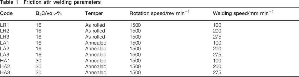
The rolled plates were cut into sections of ∼150 mm (rolling direction)×100 mm. All the plates were butt welded along the rolling direction with an MTS I-Stir PDS machine. Conical unthreaded FSW tools made of WC–15Co were used for the tests. The welding parameters were selected to avoid macrodefects in the weld and excessive flash on the surface, as listed in Table 1. All the tests were conducted in the force control mode of FSW.
Friction stir welding parameters
The micrographic, microhardness and tensile testing samples were prepared along the transverse cross-sections of the joints. They were cut perpendicular to the weld at positions where the FSW process is considered stable based on ultrasonic inspection. For each condition, at least two micrographic and three tensile samples were used. Microstructural characterisation was performed using an OM with an image analyser and an SEM equipped for electron backscatter diffraction. Particle characterisation was conducted in both nugget and BM using the image analyser at ×500 magnification. A total of 64 fields (190×140 μm2/field) uniformly distributed in each of the analysed zones (3 mm wide) were actually measured to increase the statistical accuracy. Vickers hardness of the matrix is also measured at the top and bottom of each joint at intervals of ∼0·5 mm using a 10 g load indent. The tensile tests were carried out according to the ASTM E8-04 standard (rectangular flat samples with a 12·5 mm width reduced section) at a test speed of 1 mm min−1 using a 50 mm gage extensometer centred on the weld position. Tensile samples were prepared according to the standard on as welded samples without any change of sample surface.
Results and discussion
Microstructures
All the FSW joints of AA 1100–B4C materials were inspected from the bottom side by ultrasound in an immersion bath before further analyses to ensure that they were sound and free of macrodefects. The ultrasonic inspections were performed with a focused shape transducer operating at 30 MHz. The inspection results for a defect free weld and for a weld with discontinuous defects are presented in Fig. 1a and b respectively. It should be noted that any non-uniformity in the inspected materials (larger than ∼120 μm) will cause a change in the ultrasonic wave propagation and generate a different colour from the blue background colour. Therefore, some welding defects and particle clusters in the AA 1100–B4C composite materials could behave in a similar way during ultrasonic inspection. Careful analysis of discontinuities has to be made with the inspection software to distinguish between welding defects and particle clusters. According to the analysis, most of the spots (change of colour) outside of the welded zone are due to particle clusters. It is remarkable that the FSW process significantly reduced the number of particle clusters in the stirred zone, as shown in Fig. 1a. The discontinuous defects in the welded zone (Fig. 1b) are usually caused by insufficient forging force and can be avoided by setting the welding parameters accordingly.
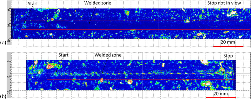
Typical ultrasonic inspection images of FSW joints of AA 1100–16 vol.-%B4C MMCs
A typical macroscopic overview of the sound weld cross-section is shown in Fig. 2. The stirred zone (nugget), the thermomechanically affected zone (TMAZ) and the heat affected zone (HAZ), as well as the BM, can be roughly identified by colour change due to the different thermomechanical histories of the materials. The typical defects found in the fusion welding joints, such as particle segregation, porosity and chemical reaction, are not observed in the FSW joints.
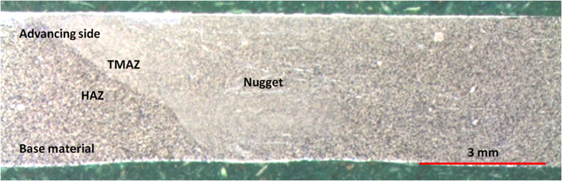
Typical macrograph of FSW joint of AA 1100–16 vol.-%B4C composite: weld zone on retreating side cannot be clearly identified
B4C particle characterisation
Image analyser results show similar average volume concentrations of B4C particles in the nugget zones and BMs. The measured B4C concentrations are 15±1% in the nugget and 16±1% in the BM for Al–16 vol.-%B4C MMCs and 32±1% in the nugget and 33±1% in the BM for Al–30 vol.-%B4C MMCs.
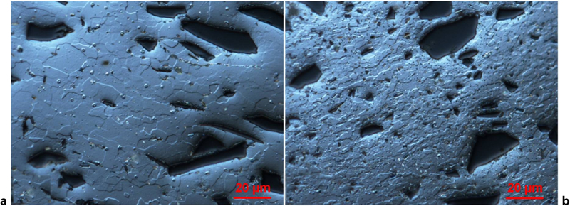
Although the FSW process does not affect the B4C volume concentration, it should be noted that significant particle size and shape changes are observed in the weld zone. As illustrated in Fig. 3, breakage of B4C particles occurs in both materials, and typical micrographs of the base and welded materials clearly show this feature.
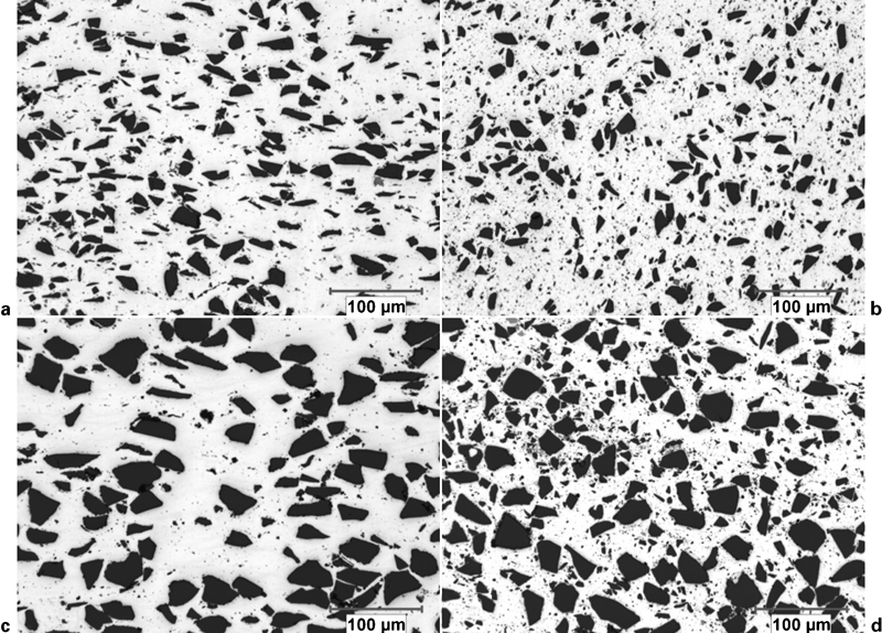
Typical optical micrographs of a base material and b nugget zone of Al–16B4C MMCs (LR3) and c base material and d nugget zone of Al–30B4C MMCs (HA1)
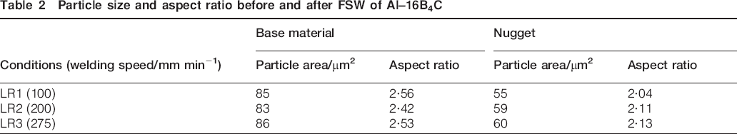
Typical B4C particle size and shape histograms are plotted in Fig. 4 for both materials. Particle size analyses were carried out with great care using the image analysis software to avoid counting intermetallics (fine and grey particles) as B4C particles (black particles). Furthermore, particles for which the cross-sectional area is <2 μm2 are not counted due to measurement uncertainties. Obviously, the amount of finer B4C particles increases significantly in the nugget for both materials. For Al–16B4C MMCs (LR3), the average particle area decreased from 86±5 μm2 (BM) to 60±5 μm2 (nugget), while for Al–30B4C MMCs (HA1), this average value decreased from 186±5 to 109±5 μm2. Similar results were also obtained in the FSW of Al–SiC and Al–Al2O3 MMCs. 4 4,11 On the other hand, the particle aspect ratio is significantly reduced (from 2·53±0·02 to 2·13±0·02) in the Al–16B4C MMCs. This rounding effect may be due to the breaking and possible abrasion of the B4C particles during FSW of this Al composite. However, the particle aspect ratio for Al–30B4C MMCs does not change significantly (constant average value of 1·92±0·02). The reason for this different behaviour is unclear, but the smaller aspect ratio of B4C particles, the difference in the initial particle distribution and the higher viscosity of the material during FSW surely play a role. In our study, the influence of welding speed on particle breakage and aspect ratio was investigated in Al–16B4C MMCs, and the results are given in Table 2. A similar behaviour of the particle breakage was observed in both as rolled and annealed conditions, and the welding speed did not have a significant influence on the particle breakage and roundness.
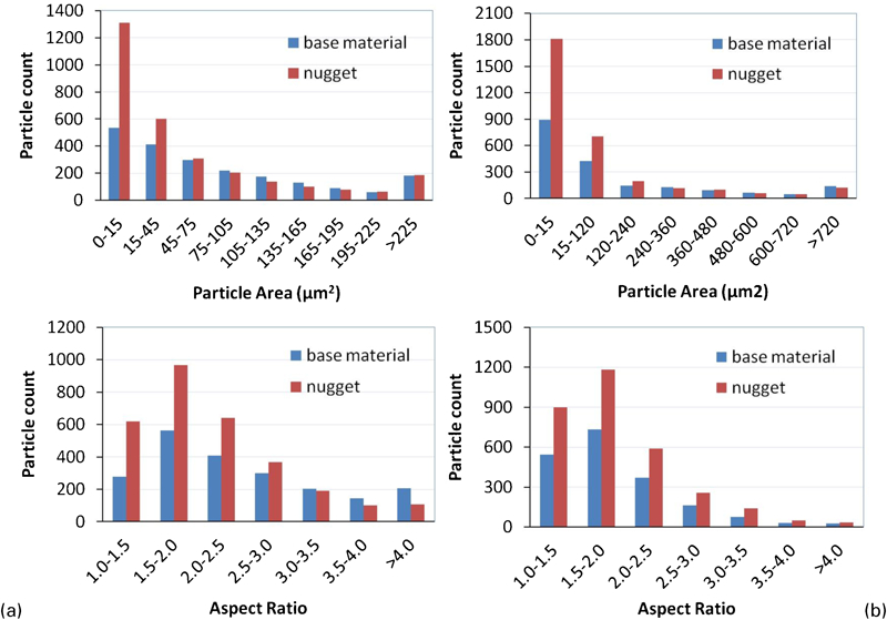
Particle area and aspect ratio histograms measured in base material and FSW nugget of both a Al–16B4C and b Al–30B4C MMCs
Particle size and aspect ratio before and after FSW of Al–16B4C
Optical microscopy showed that the distribution of B4C particles in the stirred zone is more homogeneous than that of the BM. Particle clusters and arrangement along the rolling direction found in the BM have completely disappeared in the stirred zone. A similar phenomenon was also reported in the FSW of Al–SiC6 and Al–B4C MMCs.5 This can be attributed to the physical stirring effect of the FSW tool and is very favourable here since homogeneous B4C particle distribution is of primary importance in nuclear applications.
Grain refinement of aluminium matrix
Significant grain refinement of the aluminium matrix was observed in the stirred zones of both 16 and 30%B4C composite materials. Comparing the BM and nugget zone grain structures in Fig. 5 reveals the grain refinement effect in an example of the 16%B4C composite material. As shown in Fig. 5, the average grain size of the 16%B4C composite material is reduced from ∼15 μm in the BM to ∼5 μm in the nugget zone (estimate based on OM observation after etching). Refinement of the grain structure is mainly attributed to the effects of plastic deformation and thermomechanical cycle during FSW. A similar grain refinement in the nugget has also been reported in the literature for different aluminium alloys. 12 12,13 In the case of MMCs, other authors have confirmed a similar recrystallisation process for FSW of Al–SiC,6 Al–B4C5 and other MMCs.
Grain structure of as rolled AA 1100–16 vol.-%B4C MMCs
Microhardness
The microhardness profiles measured in the FSW joint of as rolled AA 1100–16%B4C MMCs show an increase in hardness in the nugget zone for all welding conditions, as shown in Fig. 6a. This can be related to the much finer grain size in the nugget and the hardening effect of the fine broken particles embedded in the matrix. A softened region can be observed in the weld of the strain hardened monolithic alloys, as previously reported. 14 14,15 However, in this study, the hardening effect of grain refinement and the fine broken particles embedded in the matrix overcome the softening effect. It is important to note that the minimum hardness for the as rolled Al–16B4C is observed in the transition zone of the weld, where there is an annealing effect by the FSW thermal cycle. Such minimum does not exist in the microhardness profiles of the annealed material (Fig. 6b). Moreover, the hardening effect in the stirred zone is also confirmed for the annealed material.
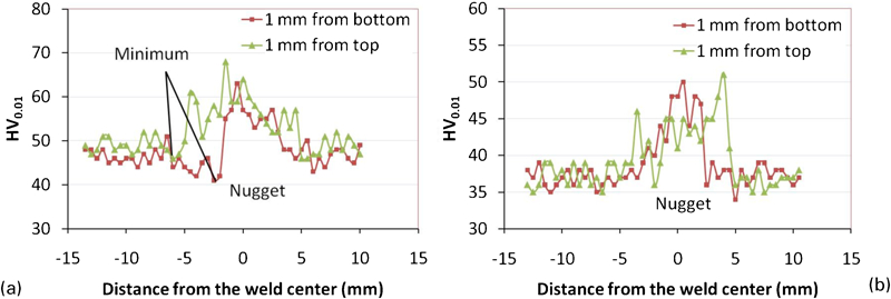
Microhardness profiles across FSW joints of a as rolled AA 1100–16%B4C MMCs (LR3) and b annealed AA 1100–16%B4C MMCs (LA3)
The microhardness in the FSW joints of AA 1100–30%B4C MMCs has not been measured since the interparticle distance is not sufficient to allow the implementation of an effective indent even with 10 gf.
Tensile properties
Transverse tensile tests of all FSW joints were carried out to examine the effects of FSW parameters on the mechanical properties of welded assemblies. For comparison purposes, the BMs in the corresponding temper were also tested perpendicular to the rolling direction. Table 3 lists the tensile properties of BMs and FSW joints of corresponding materials. Generally, the tensile results show high joint efficiency for both composite materials, up to 100% for the joints made from annealed materials.
Tensile tests of base materials and FSW joints for Al–B4C MMCs
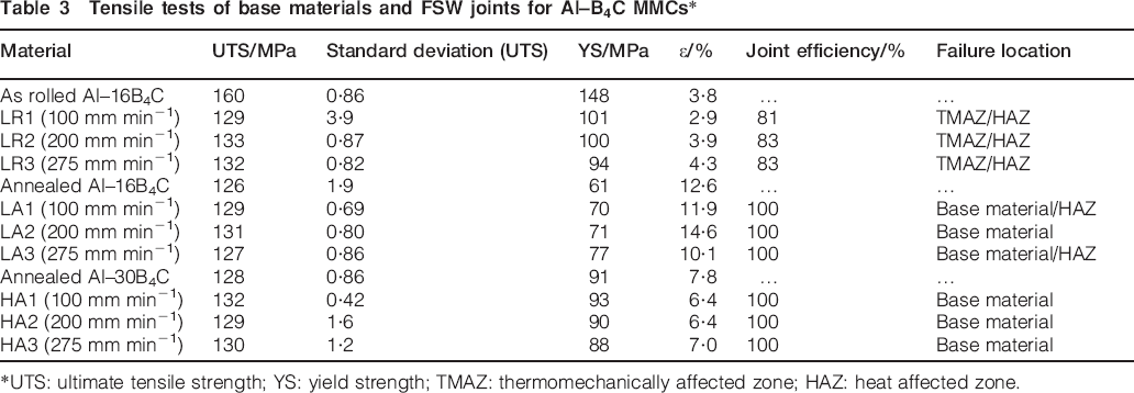
UTS: ultimate tensile strength; YS: yield strength; TMAZ: thermomechanically affected zone; HAZ: heat affected zone.
The decrease in the ultimate tensile strength (UTS) and yield strength (YS) of the as rolled AA 1100–16 vol.-%B4C MMCs is due to the annealing effect induced by the thermal cycle during FSW. As shown in Table 3, the failure location of the joints occurs in the transition zone (TMAZ/HAZ), which is also the position for the minimum value in the microhardness profile. Figure 7 shows the electron backscatter diffraction maps from the BM and HAZ. In the as rolled BM, there are a number of dislocation networks (low angles, 2–5°), while in the HAZ, the heat generated during welding causes the recovery to take place and most dislocation networks to disappear, resulting in a drop in the strength and hardness.
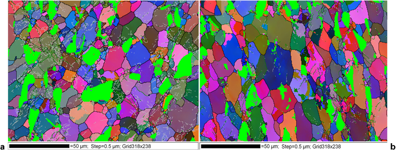
Electron backscatter diffraction maps showing grain structure for a as rolled base material and b corresponding HAZ: green regions are B4C particles while other colour regions represent orientation of Al grains (black lines, >15°; green lines, 5–15°; grey lines, 2–5°)
For this material, the increase in welding speed from 100 to 275 mm min−1 does not have a significant effect on the UTS and YS, which is somewhat unexpected according to the literature on FSW of strain hardened pure aluminium. 15 15,16 The non-effect of welding speed on the mechanical properties of welded as rolled MMC materials compared with monolithic strain hardened aluminium alloys may be attributed to the higher heat generation during the FSW of MMCs. Indeed, a higher heat is expected during the FSW of Al–B4C composites due to their lower thermal conductivity (173 W m−1 K−1 for Al–15B4C and 222 W m−1 K−1 for AA 1100–O). 17 17,18
On the other hand, the FSW joints of the annealed MMC materials, for both B4C concentrations, show UTS, YS and elongation values comparable to those of the corresponding BMs. The variation of welding speed from 100 to 275 mm min−1, as expected, does not show a significant effect. This is understandable as the materials are already in the fully annealed condition, which negates the softening effect of the FSW thermal cycle.
It is worthwhile to highlight the fact that all the tensile samples made of MMCs with 30 vol.-%B4C and most of the tensile samples made of MMCs with 16 vol.-%B4C in the annealed condition failed in the BMs. This indicates that the FSW joints of these MMCs are stronger than the BMs, which is very unusual for aluminium based material welding. This is related to the grain refinement of the matrix resulting from the FSW process. It is interesting to note that the FSW joints of the as rolled samples show a good consistency in terms of tensile properties, as indicated by the low standard deviation values on repeated measurements.
Comparison of the tensile data between the FSW joints of as rolled and annealed AA 1100–16%B4C MMCs indicates that the starting temper of the materials does not have much influence on the final UTS of the joints but has a significant effect on elongation ϵ. The annealed starting temper is recommended as far as tensile property values are concerned; as for similar UTS, the welded samples give higher elongation.
Fractography
After tensile testing, the fracture surfaces of the BM and FSW joints of the AA 1100–16%B4C MMCs were examined by SEM to investigate the effects of FSW on fracture behaviour. The results of typical SEM microimages are shown in Fig. 8. The fracture of particulate reinforced MMCs under tensile loading is controlled by three main mechanisms depending upon the nature of the matrix, reinforcement and interface: 19 19,20
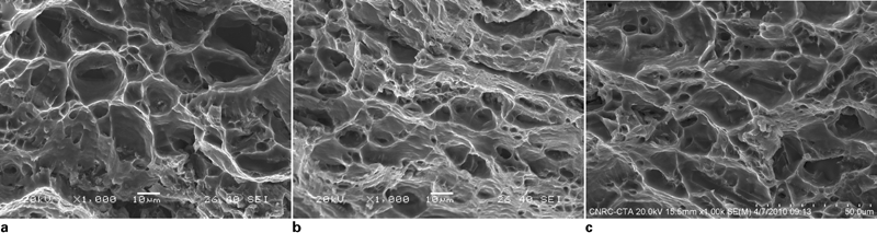
Images (SEM) of tensile fracture surfaces of a as rolled base material, b FSW joint (LA1) and c annealed base material
if the matrix is very strong and the local stress exceeds the fracture stress of the reinforcement particle, then particle fracture will occur
if the local stress is lower than the particle fracture strength but is higher than the interfacial strength, then interfacial decohesion occurs
if both interface and reinforcement are stronger than the matrix, then fracture takes place by void coalescence of the matrix.
In the as rolled materials, large interfacial voids, resulting from decohesion between B4C particles and matrix, are the main characteristics of the fracture (Fig. 8a). Particle fracture was occasionally observed, but a large portion of the fracture consisted of interfacial decohesion. The local stresses were not large enough to fracture the majority of the particles but exceeded the interface strength, which resulted in interfacial voiding.
In the FSW joints of the as rolled material, failure occurs in the transition zone (TMAZ/HAZ). The fractograph (Fig. 8b) shows extensive ductile dimpling in the matrix with occasional small interfacial voids between particles and matrix. As the tensile strength decreased significantly after FSW of the as rolled material, the void coalescence of the matrix became the dominant feature. The rupture surface is due to the finer particles in the TMAZ zone compared with the BMs and easier plastic deformation of the aluminium matrix annealed by FSW.
On the other hand, the fracture surfaces of the annealed BM and the corresponding FSW joints are very similar, and the morphology can be characterised as major ductile dimpling in the matrix with a small fraction of interfacial decohesion (Fig. 8c). The scale of the matrix dimples and interfacial voids is coarser than that found in the FSW joints of the as rolled material, as shown in Fig. 8b. This is because the failures of the FSW joints of the annealed materials are located in the HAZ or BM, where there was no refinement of both particles and matrix. In both cases (annealed BM and its FSW joints), the materials were already fully annealed, and the tensile strengths were low. The annealed AA 1100 matrix is very soft, and therefore, it is understandable that the AA 1100 aluminium matrix tends to fail before the fracture of B4C particles and interfacial decohesion.
Conclusions
Friction stir welding is an excellent welding technique for joining AA 1100 based MMCs reinforced with B4C particles up to 30% volume fraction. Joint efficiencies (UTS) higher than 81% are obtained for the as rolled AA 1100–16 vol.-%B4C composite and up to 100% for both annealed AA 1100–16 vol.-% and AA 1100–30 vol.-%B4C composite materials.
Breakage and fragmentation of ceramic and constituent particles during FSW are noted. While the particle size distribution stays monomodal after FSW, the average particle cross-sectional area decreases from 86 to 60 μm2 for the 16%B4C composite and from 186 to 109 μm2 for the 30%B4C composite respectively. Some rounding has also been observed after welding, with a particle aspect ratio varying from 2·5 to 2·1 after welding of the 16%B4C concentration composite.
The annealed starting temper is generally recommended for AA 1100 based MMCs as their FSW joints have equal UTS at ∼130 MPa and higher elongation compared with those of the as rolled condition.
The grain refinement of the aluminium matrix (from 15 to 5 μm for AA 1100–16%B4C) induced by FSW contributes to the high tensile properties of FSW joints.
Footnotes
Acknowledgements
The authors would like to acknowledge the financial support from the Natural Sciences and Engineering Research Council of Canada (NSERC), Rio Tinto Alcan and NRC Aluminium Technology Centre. They also wish to thank Mr F. Nadeau for the technical support in welding.