
Abstract
The instability of gas metal arc welding in pure Ar shielding gas is associated with the structure of the coaxial multilayer solid (CMS) wire. This wire has a coaxial double structure consisting of a different composition in its inner and outer parts. In this paper, four CMS wires were developed to investigate the influence of the wire structure on the welding behaviour. First, the wire melting behaviour was observed with a high speed video camera system. Then, the relation between the welding instability and the length of the column of liquid molten metal, which causes arc instability, was analysed. Next, a wire melting simulation of the CMS wire was carried out to discuss the effect of the wire structure on the melting behaviour. Finally, the welding stability was investigated at the V groove. An excellent bead shape was obtained, and stable welding was found to be possible using an appropriate wire structure.
Keywords
Introduction
The structure of a coaxial multilayer solid wire (CMS wire) was studied to enable stable gas metal arc (GMA) welding in pure Ar shielding gas (Ar GMA welding). This wire has a coaxial double structure with a different composition in its inner and outer parts. 1 1,2 The two characteristics of this wire are that it can perform stable welding in pure Ar shielding gas under appropriate conditions and that it can improve the characteristics of the weld metal. Generally, the Ar GMA welding becomes unstable using a conventional solid wire by the formation of a column of liquid molten metal (CLM) at the wire tip. However, the formation of CLM can be prevented using CMS wires and stable welding can be achieved. 1 1,2 The mean composition of the CMS wires was the same as that of the solid wire. 2 2,3 The toughness and ductility of the weld metal improved since the oxygen in the weld metal, which deteriorates the toughness and ductility,4 decreased due to the pure Ar shielding gas.
To prevent the formation of CLM in the CMS wire, a design guide for choosing a suitable combination of inner and outer materials was proposed.5 The wire melting behaviour depends on the combination of materials and wire structure, which is the ratio of the inner and outer parts. Therefore, both of these factors are important to enable stable GMA welding in pure Ar shielding gas. In this paper, the influence of the wire structure on the melting behaviour of the CMS wire was investigated and the influence on the welding stability was discussed. First, four CMS wires were developed, which had different ratios of the inner and outer areas. The wire melting behaviour was observed with a high speed video camera and the welding stability was investigated by bead on plate welding. Next, a wire melting model of the CMS wire was used to discuss the influence of the wire structure on the melting behaviour.5 Here, wire temperature and tip shape were investigated. Finally, the welding stability was examined at the V groove. A CMS wire with an appropriate wire structure was able to carry out stable Ar GMA welding at the V groove.
Materials and methods
Wire structure of CMS wire
Four CMS wires expressed as HFIN-4, HFIN-8, HFIN-12 and HFIN-16 were developed to investigate the wire melting behaviour. Inconel was used for the inner part, and steel was used for the outer part, since the difference of the melting temperature was >180 K. The chemical compositions of Inconel and steel are shown in Table 1. The wire structure and the cross-section of the wires are shown in Figs. 1 and 2 respectively. The average inner diameter, average thickness of the outer part, cross-sectional area of the inner part and cross-sectional area of the wire area are expressed as dIN, HOUT, SIN and SALL respectively. The nickel average content of the CMS wire is 6–25%. Therefore, to compare the melting behaviour of a wire, 10% nickel stainless steel wire was used because nickel average content was near CMS wires.
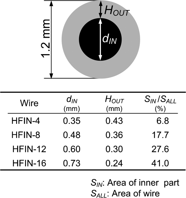
Dimension of developed CMS wire
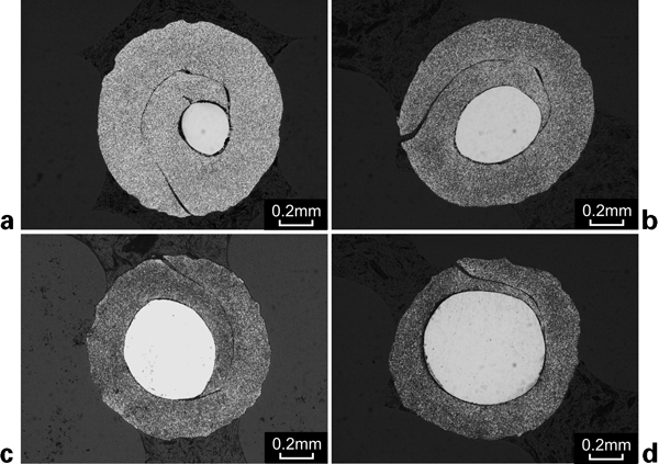
Cross-section of developed CMS wire
Chemical compositions of CMS wire
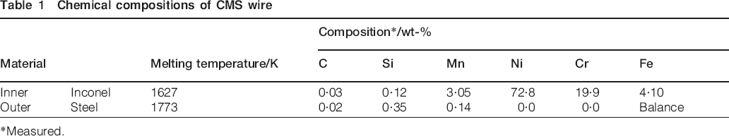
*Measured.
Welding method
We observed the wire melting behaviour in pure Ar shielding gas using a high speed video camera system (frame rate, 9000 frames/s). The purity of the Ar shielding gas was 99·998%. The bead on plate welding and V groove welding were carried out. Plates of low carbon steel (JISZ3136SM490B; 50×250×12 mm, 50×250×19 mm) were used, and the surfaces were machined to remove the mill scale. The constant voltage power source was used, and the welding was operated with electrode positive. The welding conditions were as follows: welding current of 240–300 A, voltage of 35–37 V, welding speed of 5·8 mm s−1, shielding gas flowrate of 25 L min−1 and distance between the contact tip and the specimen of 25 mm.
Results and discussion
Influence of wire structure on column formation
Figure 3 shows the melting behaviour of a conventional solid wire in pure Ar shielding gas. A long thin CLM formed at the wire tip of a stainless solid wire (10Cr–10Ni) and moved irregularly, indicating the welding instability of Ar GMA welding. 1 1,2 Figure 4 shows the wire melting behaviour of CMS wires. A CLM was generated at the tip of HFIN-4 and HFIN-8; however, their lengths were shorter than that of the solid wire. On the other hand, a CLM did not form on HFIN-12 and HFIN-16, and sphere shaped droplets were observed instead. Next, the effect of the wire structure on the length of CLM was investigated. A CLM is defined as the part that is narrower than the wire diameter dwire. Figure 5 shows the change in the length of the CLM. The average length of the CLM for the solid wire is ∼5·5 mm. The CLM length of HFIN-4 (SIN/SALL = 6·8%) and HFIN-8 (SIN/SALL = 17·7%) is ∼3·5 mm and that of HFIN-12 (SIN/SALL = 27·6%) and HFIN-16 (SIN/SALL = 41·0%) is ∼2·0 mm. The fluctuation bands of HFIN-12 and HFIN-16 become narrower than that of HFIN-4, HFIN-8 and the solid wire. This figure shows that the CLM can be shortened by increasing the value of SIN/SALL to >28%.
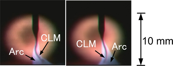
Unstable wire melting behaviour of solid wire in pure Ar shielding gas
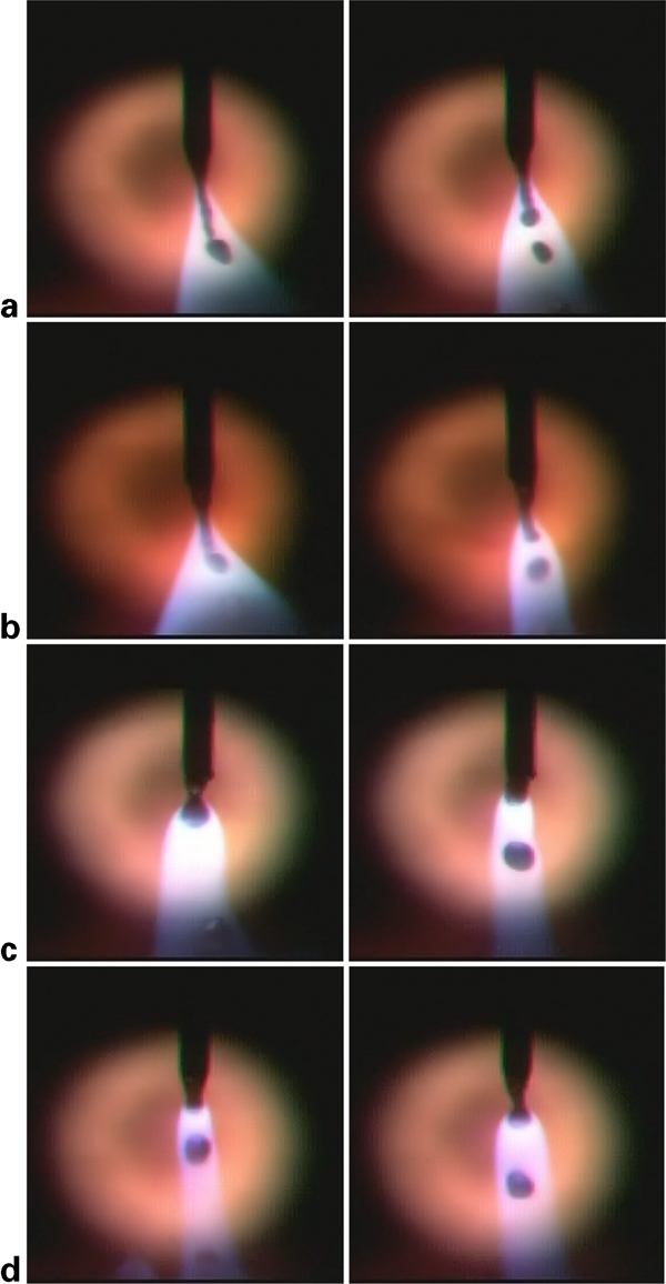
Wire melting behaviour of developed CMS wires
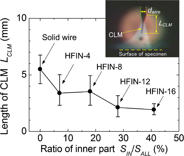
Effect of wire structure on length of CLM in pure Ar shielding gas
The CLM behaviour has an influence on the welding stability. The current–voltage characteristics: the welding current and the voltage between the contact tip and the specimen, were examined to investigate the welding stability using HFIN-4 and HFIN-12 and the results were plotted as shown in Fig. 6. Figure 6a and c shows the average current Iav and the average voltage Vav. The change in the voltage is small due to the constant voltage characteristics of the power source. However, the current varied from 80 to 480 A with a difference of 400 A, as shown in Fig. 6a. The irregular changes in the current indicated by arrows are shown in Fig. 6b. This irregular change in current is caused by the irregular movement of the CLM shown in Fig. 4. This movement produces the irregular change in the arc length, resulting in arc instability. Therefore, the weld behaviour becomes increasingly unstable as the length of CLM increases. In contrast, the change in the current of HFIN-12 is small, and the difference is 140 A, as shown in Fig. 6c. Figure 6d shows that the fluctuation in the current of HFIN-12 is small compared with that of HFIN-4. The welding is stable due to the short CLM.
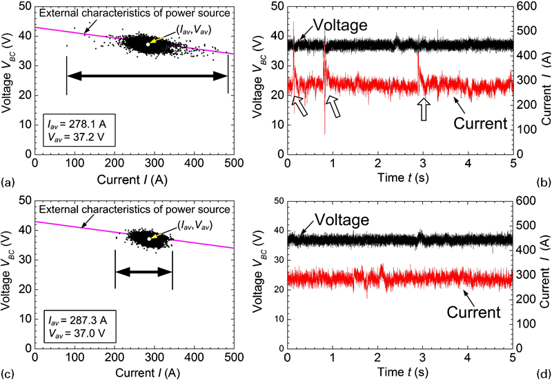
Effect of wire structure on welding current and voltage in bead on welding in pure Ar shielding gas
Wire melting behaviour of CMS wire
A wire melting simulation system of the CMS wire
5
5,6 was carried out using Inconel and steel
for the inner and outer materials respectively to discuss the wire melting
behaviour. Wires with an overall diameter of 1·2 mm and inner part
diameters of 0·3, 0·6 and 0·9 mm led to ratios of SIN/SALL
of 6·3, 25·0 and 56·3% respectively. It was assumed
that if the temperature of the mesh T is satisfied by the
equation

Simulation results of wire melting behaviour of CMS wire
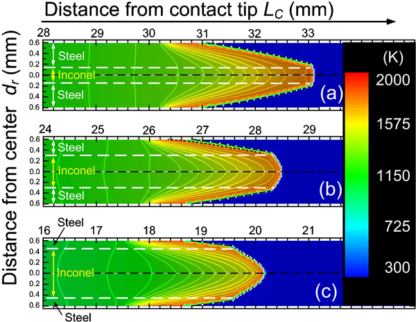
The axial cross-sections after the welding of HFIN-8 and HFIN-16 shown in Fig. 8a and b respectively are used to discuss the melting behaviour of the CMS wire. A cavity was observed in the inner part of Fig. 8a, while that of Fig. 8b displayed a convex shape. To investigate the melting behaviour of the inner and outer parts, the melting temperatures of Inconel (1627 K, dotted line) and steel (1773 K, broken line) were plotted as shown in Fig. 9. The shaded area of the inner and outer parts in Fig. 9a represents a solid state since the temperature there is less than the melting temperature. Area A corresponds to the melted area of Inconel, where the distance from the centre dr is <0·15 mm with a depth of 0·8 mm. The cavity shown in Fig. 8a occurred by the preferential melting and the flowing out of the melted materials from the inner part. Area B is the melted area of steel, which appears outside of the solid steel. The shaded area in the inner part of Fig. 9b and the shape of the melted area A are both convex. The melting behaviour is dominant in the inner part due to the large ratio of the inner area and the effect of the outer area. A similar tendency is shown in the inner part in Fig. 8b, which acquired a convex shape. Therefore, the ratio of the inner part is important for changing the wire melting behaviour. Although the flow of molten metal was not considered in this simulation, the simulation and experiment showed a similar tendency in the melting behaviour. The flow behaviour in the inner and outer parts should be considered for a more detailed discussion of the melting behaviour.
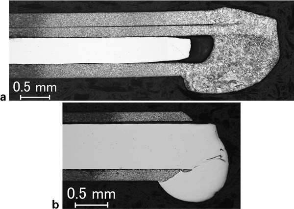
Longitudinal sections after welding
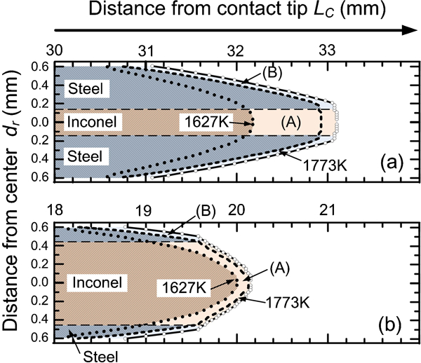
Simulation results of melting and solid areas at wire tip
V groove welding stability
The wire structure provides a large influence on the welding stability in the V groove. First, the welding behaviour of the stainless solid wire (10Cr–10Ni) was investigated. The current–voltage characteristics, the fluctuation in the current and voltage, are shown in Fig. 10. The average current Iav and the average voltage Vav are plotted in Fig. 10a. The current varies from 120 to 480 A with a difference of 360 A. The irregular change in the current, indicated by arrows, is shown in Fig. 10b. This irregular current change causes the wire tip to move up and down irregularly2 and makes it difficult to keep the wire tip at the same position, thus producing many undercuts at the bead.
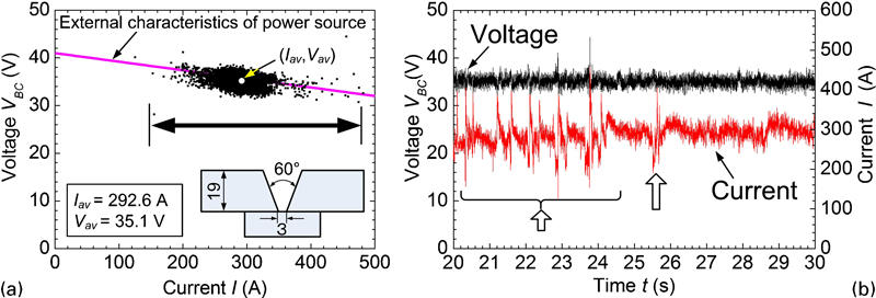
Change in welding current and voltage in V groove welding in pure Ar shielding gas
The current of HFIN-8 has a large variation from 80 to 480 A with a difference of 400 A, as shown in Fig. 11a. The irregular change in current is shown in Fig. 11b. The wire melting behaviour is similar to that of a solid wire due to the formation of a CLM at the wire tip. Therefore, stable welding is difficult, and undercuts occur, as shown in Fig. 12a. In contrast, the variation and fluctuation of the current in HFIN-12 are small, as shown in Fig. 11c and d respectively. This indicates that stable welding is possible at the V groove since the formation of the CLM was prevented. Therefore, a good bead shape was obtained, as shown in Fig. 12b.
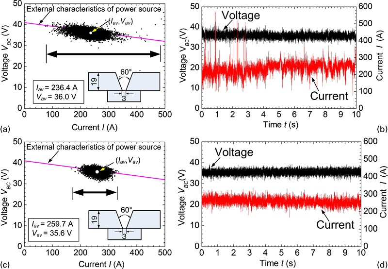
Effect of wire structure on welding current and voltage at V groove welding in pure Ar shielding gas
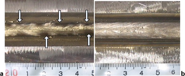
Bead shape at V groove in pure Ar shielding gas
As mentioned above, stable welding can be carried out in pure Ar shielding gas by shortening the CLM that is dependent on the wire structure. The generation of the CLM behaviour also depends on the materials’ properties of the inner and outer parts. 5 5,6 Therefore, a wire structure with an appropriate composition is important for achieving a stable Ar GMA welding.
Conclusions
The influence of the welding stability of GMA welding in pure Ar shielding gas on the structure of wire was investigated. It is indicated that the wire melting behaviour and the formation of a CLM depended on the wire structure, which is the ratio of the inner and outer parts. The results are as follows.
The wire melting behaviour was observed using a high speed video camera system. A CLM formed at the wire tip when the value of SIN/SALL was <18% but did not form when it exceeded 28%, enabling stable welding by bead on plate welding.
The wire melting simulation was used to discuss the melting behaviour of the CMS wire. The melting in the inner part is important for the wire melting behaviour. Although the flow of molten metal was not considered in this simulation, the CMS wire and the simulation showed a similar tendency in the melting behaviour.
The welding stability was investigated at the V groove, and an excellent bead shape was obtained there using an appropriate wire structure.
Footnotes
Acknowledgements
This research was supported by KAKENHI (grant no. 18360358) and was achieved by collaboration with Nippon Welding Rod Co., Ltd, which is supported by the New Energy Industrial Technology Development Organization (NEDO), Japan.