
Abstract
Magnesium AZ31 sheets have been lap welded with magnetic pulse welding using H shaped symmetric coils connected to a Pulsar MPW-25 capacitor bank. The joints displayed an increasing trend in strength with discharge energy. The weld morphology consisted of twin bond zones separated by an unbonded centre zone. Metallographic examination of the unbonded centre zone revealed anisotropic deformation and a lack cleaning from the interface. This zone forms as a result of normal impact in the initial stage of collision. Transmission electron microscopy of the bond zone revealed a continuous interface having an 8–25 μm thick interlayer with dislocation cell structure and distinct boundaries with adjacent material. The interlayer may have formed in a semisolid state at elevated temperature. The interlayer corresponds to a ductile fracture surface and is responsible for the joint's high strength. Nanoscale grains were found beside the interlayer as well as larger, highly elongated grains.
Introduction
Impact welding, in general, is a set of processes that utilise a rapid energy source to accelerate and cause collision between two metal surfaces at high enough velocity to achieve bonding through contaminant and oxide removal. This cleaning takes place via jetting, which occurs as a result of shear strain localisation at the interface.1 Different sources of driving pressure are used in impact welding, such as chemical explosives in explosion welding (EXW) or the repulsive interaction between strong pulsed magnetic fields, as in the case of magnetic pulse welding (MPW). In EXW, after a short initial transient stage, the oblique collision angle β at which the sheet surfaces meet and which affects bonding success remains constant throughout welding.2 As a result, bonding morphology occurred consistently over a large interfacial area. Welds can be successfully produced when the angle β is within an acceptable range. However, the bond morphology in MPW joints is significantly different because β is transient through bonding.
Using MPW, Aizawa3 was the first to successfully weld two flat aluminium sheets in a lap joint configuration. Currently, most MPW research is focused on joining dissimilar metal combinations, with primary interest in the resulting joint mechanical properties in connection to the formation of intermediate phases at the weld interface.4– 7 For example, recently, Song et al. 8 characterised the steel–Ti dissimilar EXW joint hierarchical structure from macro- to nanoscopic level and found the mechanical properties to heavily depend on intermetallic formation. However, there exists limited understanding on the connection between the microstructural features of similar metal MPW welds and the mechanical properties without the formation of intermetallics. Research in MPW between similar metals has been limited to pure aluminium or copper or alloys thereof.9– 12 No fusion-like features were found in similar material welds of these studies. Moreover, transmission electron microscopy (TEM) analysis revealed various peculiarities at the interface, including grain refinement to a submicrometre level in Al and Cu welds,13 indicating severe plastic deformation.
Owing to the increasing wrought Mg used in the automotive industry, there is a need to develop joining processes for Mg sheet metal. At present, there is no report on the joining of magnesium to magnesium alloys using MPW or other forms of impact welding. In the current work, MPW was utilised to join wrought magnesium alloy sheet to itself. Metallurgical analysis was then conducted to characterise the microstructures at various locations within the bonded joint. The observed interface microstructure was then correlated to the mechanical properties of the joint and the β angle parameter. In improving the understanding of the effect of microstructure on strength, an approach can be made to improve the practicality of the joint and process.
Experimental
Twin roll cast sheets of AZ31-H24 magnesium commercial grade alloy from POSCO were used in this study. The chemical composition of the alloy was 3·02 wt-%Al, 0·80 wt-%Zn, 0·3 wt-%Mn, 0·01 wt-%Si and Mg remainder. Welding specimens of 90×40×0·6 mm were cut with the 90 mm edge oriented parallel to the rolling direction. Before welding, all the specimens were degreased by wiping with acetone.
Magnetic pulse welds were produced using custom symmetric H shaped copper alloy 110 coils (Fig. 1) connected to a Pulsar MPW-25 machine, which consists of a capacitor bank, high voltage charging power supply, a spark gap high voltage switch and discharge circuit connected to the coils. Each coil concentrated the current through a 9×7×3 mm section, and the overall length of the concentrator including fillets is 23 mm. The coil geometry is based on the heuristic designs of Aizawa3 and Kore et al. 10 The actual weld was formed on the specimens within the area overlapped by the current concentrator. As indicated in Fig. 1, the welding direction was coincident with the rolling direction.
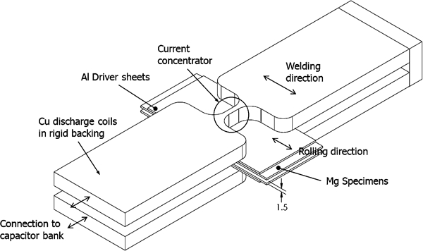
Schematic diagram of H shaped coils used and assembly of welding specimens between coils
To initiate welding, high amplitude, high frequency current was discharged from the 539 μF capacitor bank and travelled through both coils. As this current passed through the coils, a magnetic field surrounding the coils was generated. The generated magnetic field was strongest along the current concentrator section of the coil. The generated magnetic field induces eddy currents in the sheet materials located between the H shaped coils.
Owing to the low electrical conductivity of Mg, 0·8 mm thick commercially pure AA 1100 aluminium sheets were used as driver plates and placed between the magnesium sheets and the coils. The higher conductivity of pure aluminium allowed a larger amount of eddy current to be generated and thus stronger repulsive interaction between it and the coil than in the case of Mg sheet alone. A 1·5 mm standoff gap was set up between the welding specimens, and they were placed in the coil assembly, as shown in Fig. 1.
The induced currents in the aluminium driver sheets generated their own magnetic field having an opposite polarity to the field surrounding the coils. The repulsive interaction between the opposing magnetic fields accelerates the driver and Mg specimens away from the coils towards each other. As a consequence, the welding specimens collide at high velocity.
All the specimens used for metallographic examination were sectioned along the welding direction, cold mounted and mechanically polished to 1 μm finish. The specimens were then chemically polished for 5 s in 10% nital solution and etched for 10 s in a solution of 4·2 g picric acid, 10 mL acetic acid, 70 mL ethanol and 10 mL water. The microstructures of the welds were examined using an optical microscope and a JEOL JSM-6460 scanning electron microscope (SEM) equipped with an Oxford ultrathin window detector energy dispersive spectrometer. To examine the weld interface in detail, focused ion beam milling was used to prepare a thin foil TEM sample. The location from which the sample was cut is shown in Fig. 2, the detailed microstructure of which is discussed in the section on ‘Bond zone’. The welded substructures were observed with a Philips CM12 TEM operated at 120 kV accelerating voltage.
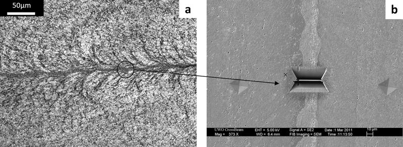
a optical microscope image showing location for TEM sample and b SEM image of focused ion beam cut sample before removal: this weld made using 12·1 kJ discharge energy
Results and discussion
Joint formation
Figure 3 shows a photomicrograph of a typical cross-section of a magnetic pulse weld between two AZ31 magnesium alloy sheets. Overall, the cross-section of the weld is symmetric with respect to a vertical line through the centre of the bonded sample. Within the width of the impacted area, there is one unbonded centre zone, two bond zones and two unbonded outer zones. As illustrated in Fig. 3, bonding clearly did not occur along the 3 mm unbonded centre zone. On each side of the unbonded centre zone, there are ∼1 mm long bond zones. Beyond the bond zones, the specimen sustained impact but did not join. These two outside regions are ∼4 mm long and referred to as the unbonded outer zones.
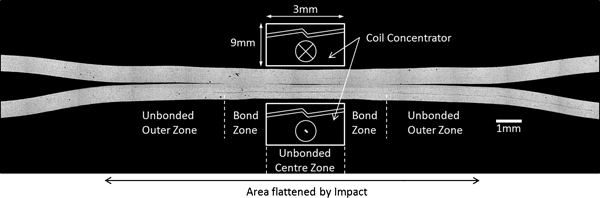
Photomicrograph showing entire cross-section of typical magnetic pulse weld
The formation of an unbonded centre zone, two bond zones and two unbonded outer zones can be explained by the changing of the collision angle β throughout the welding process. Figure 4 illustrates β and schematically represents the deformation taking place during double sided MPW, as carried out in this study. Owing to the repulsive interaction between the two opposing magnetic fields, driving pressure was formed on one side of each Mg sheet. This caused a uniform bulging deformation in each sheet. The initial contact between the sheets was normal, and the angle β was negligibly small. Given the symmetry of the initial contact, each bulge acted as a rigid barrier to the other's forward motion. However, due to the driving pressure behind each sheet, the bulges flattened against one another. As a result, two collision fronts progressed symmetrically outwards from the initial contact area of the bulge peaks. In addition, β at each front increased continuously and its value passed through the suitable range for bonding. Within this range, jetting occurred, forming the bond. Outside of the collision angle's suitable range, surface contaminants and oxides were not removed, as can be seen in the unbonded centre zone.
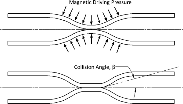
Schematic diagram showing initial impact and flattening of sheets during MPW
Figure 5 is a stitched SEM image showing the unbonded centre zone with transition to the bond zone. In the unbonded centre zone, where normal compressive loading through sheet thickness occurred, the oxide layer is still present. In the oblique collision, the removal of oxide is normally accomplished through jetting. As a result, at the oxide disappearance location, jetting of oxides and contaminates must begin to occur. The morphology of the joint, i.e. from the unbonded centre zone to the bond zone and then to the unbonded outer zone, is similar to the observations of Watanabe and Kumai.12 However, in their work, Al to Al magnetic pulse welds were not symmetric because of the single sided experimental set-up in which only one sheet was driven into the other stationary sheet. Using high speed video, Watanabe and Kumai observed that the bulged region length remained constant throughout the process and thus β continuously increased.
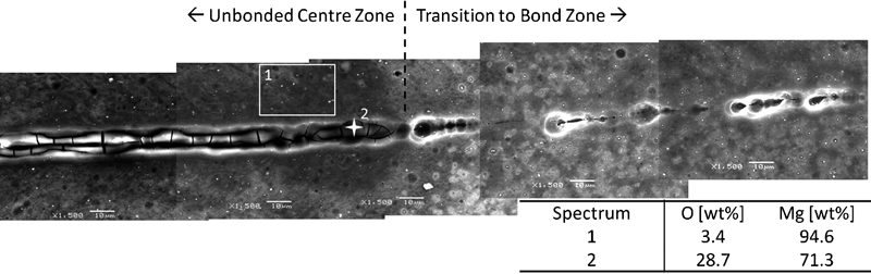
Image (SEM) showing unbonded centre zone and transition towards bond zone including energy dispersive spectrometer of oxide layer
In this study, welds were produced using 9·7–12·1 kJ of capacitor discharge energy. The resulting lap joints were shear tested using an Instron tensile machine. Figure 6 contains the typical tensile shear load–displacement curve of MPW joints and shows that one of the bonds breaks before the other in most cases and not simultaneously. The breaking load was plotted against the discharge energy, as shown in Fig. 7. Although there was considerable scatter in the measured data, the breaking loads generally increased with the discharge energy. In Fig. 7, a transition at ∼11 kJ takes place below which the strength (breaking load over subsequently measured sheared area) of the welds remains relatively constant and afterwards shows an increasing trend. This is shown by the linear trend of the breaking load up to 11 kJ discharge energy and the parabolic curve shape above 11 kJ in Fig. 7.
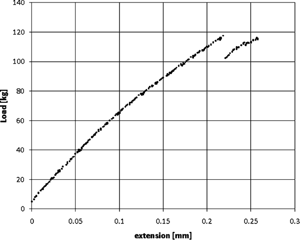
Typical tensile shear load–displacement curve of MPW joints
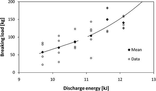
Plot of joint breaking load (kg) versus capacitor discharge energy (kJ)
Figure 8 shows the fracture surface of one bond zone each of weld samples 8 and 22 made with discharge energies of 10·2 and 11·6 kJ respectively. The bonded area of samples 8 and 22 was measured at ∼6·3 and 9·4 mm2, corresponding to joint shear strength of ∼140 and 190 MPa respectively. These numbers are within the typical 100–200 MPa shear strength range of AZ31B-H24 magnesium alloy.14 Interestingly, the thickness of the bond zone for both samples is ∼1 mm, which corresponds to the size of either bond zones shown in Fig. 3. However, the overall lengths of samples 8 and 22 are ∼3·8 and 6·4 mm respectively.
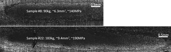
Selected sample fracture surfaces showing size of bonded area
The size of the bond zone along the welding direction is controlled by the suitable range of collision angle β in which the ejection of surface contaminate or oxide is possible. The geometry of the coil, its current concentrator dimension, the initial standoff distance between sheets, the initial gap between the sheet and the coil, the sheet thickness and the mechanical properties of the material determine the suitable range of β. On the other hand, the discharge energy of the MPW process apparently influenced the overall length of the bonded area. As shown in Fig. 8, the bonded area grew in the transverse direction as the discharge energy increased. During welding, the short length of the current concentrator created a spot-like magnetic field with the highest intensity located at the centre of the spot. As the discharge energy increased, the intensity of this field increased outwards from the centre, thus bringing more and more material into the minimum energy required for bonding. As a result, the bonded area is longer in the transverse direction at higher discharge energy.
Interface microstructure
Unbonded centre zone
Magnesium has a hexagonal close packed (hcp) crystal structure whose basal planes are closely packed. Figure 9 contains a photomicrograph showing the as received microstructure of the AZ31 magnesium alloy. During the twin roll casting process, the alloy sheet is produced such that the normal axis to the close packed planes or c axis of the hcp crystal structure in most grains is oriented perpendicular to the rolling direction.15 Since the AZ31B-H24 alloy was heat treated to the strained, partially annealed condition, the as received microstructure consists of mostly equiaxed grains (see Fig. 9).
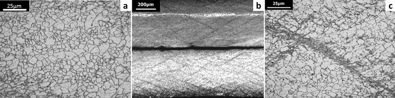
Photomicrographs showing a as received microstructure of AZ31 magnesium alloy, b unbonded centre zone and c close up of shear band
During MPW, the material within this zone experienced compressive loading along the c axis, and a reduction in thickness of approximately 15–20% occurred in the samples. However, since most of the slip systems occur along the basal planes of hcp, the normal compressive loading caused localised shear strain or twinning along the {10–12} family of planes.16 The twinning caused a rotation of the grains into a more favourable basal slip orientation. 17 17,18 Further deformation was then localised within these bands. This formed the 45° (±20°) bands observed in Fig. 10b. As illustrated in Fig. 10c, the twinning was confined within these shear bands, while the adjacent grains remained relatively undeformed. Unlike aluminium or other materials welded with MPW, this microstructural feature of Mg serves to confirm the normal nature of the initial impact and relates it to the lack of bonding.
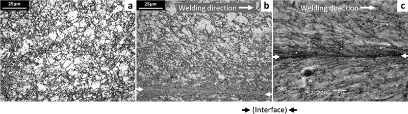
a uniform heavily twinned microstructure beside bond zone and b optical and c SEM images of bond zone: weld made using 9·7 kJ discharge energy
Bond zone
Figure 10 contains optical and SEM images showing the weld interface within the bond zone of the Mg to Mg magnetic pulse weld. The impact direction is perpendicular to the welding direction less the oblique collision angle, the value of which is unknown. Unlike in the unbonded centre zone, the diagonal shear bands were not observed in the bond zone, and the 45° lines appearing in Fig. 10 are rather elongated grains. Heavy twinning can be seen uniformly throughout most of the sheet thickness, as shown in Fig. 10a. As discussed previously, the sheets were deformed to a larger collision angle in the bond zone, and thus, loading was no longer normal through the thickness. Consequently, twinning occurred uniformly throughout with no strain localisation within the shear bands.
Figure 10 shows the relatively flat or straight interface (marked by arrows) of the bond zone of samples produced using <11 kJ discharge energy. Meanwhile, for >11 kJ discharge energy, the bond of these welds is initially flat but gradually developed into a wavy interface, as can be seen in Fig. 2a. These waves are a commonly observed phenomenon in EXW. Since the straight interface occurs only when the collision conditions are at or near the lower limit of jetting and welding,2 the preferred MPW interface would contain a larger portion of wavy than straight interface. In all the samples, within approximately 20–40 μm on each side of the interface, there is a concentration of deformation. The high magnification of the SEM image in Fig. 10b reveals that in this area, the grains were severely elongated and flowed in the welding direction.
An 8–25 μm thick undulating interlayer exists in the wavy part of the bond zone of samples having a wavy interface (Fig. 2). In EXW, both the collision angle β and the driving pressure are critical factors in jetting and interfacial wave formation.2 The interlayer and waves in the MPW welds were found in the latter part of the bond where β is larger. While comparing the bond zone with the fracture surface, the location of the wavy interlayer along the welding direction corresponds to a fine microvoiding, ductile, fracture surface, as shown in Fig. 11b. On the other hand, the straight interface at the beginning of the bond zone, above the dashed line in Fig. 11c (oxide pile-up below the line belongs to the unbonded centre zone), shows a more brittle fracture surface with large platelet-like features. It is also a part of the transition into the bond zone, as shown in Fig. 5. The microvoiding fracture is indicative of the high refinement of the interlayer and represents the increase in strength. The suggested cause for the increase in strength of samples made with higher discharge energy is the generation of a wavy interface.
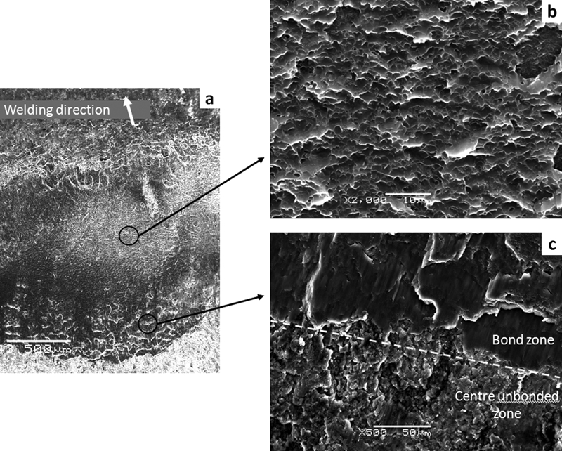
a fracture surface overview, b brittle fracture and c ductile fracture
In Fig. 12, the stitched TEM image of the weld interface, including the interlayer, is shown. The TEM image provides a perpendicular view of the weld interface with the welding direction being into the page. In the SEM image of Fig. 2, the ∼10 μm thick interlayer is clearly visible and apparently separated from the adjacent material by well defined boundary lines and colour change. Figure 13a shows the TEM image of the interlayer at higher magnification. It is found that within the interlayer, grain boundaries are difficult to distinguish, and the main structural feature is that of dispersed dislocation cells that are seemingly flattened. The interlayer is not interpreted as epitaxially solidified material because epitaxial solidification typically has very clear and observable grain boundaries. In the present work, the grain boundary was not observed even at high magnification, and the appearance suggests a highly deformed structure. Some directionality is evident as indicated by the selected area electron diffraction (SAED) pattern. From Fig. 13b, the adjacent material next to the interlayer has similar features as the interlayer in that dislocation cells and flattening are evident. The structure of this region forms a gradient transition between the interlayer and the ultrafine equiaxed grains of Fig. 13c, which were observed ∼10 μm away from the interlayer. The ultrafine grains are <300 nm in diameter and have no particular texture, as indicated by a polycrystalline-like SAED pattern. Such ultrafine grains could be the direct result of severe shear strain19 or dynamic recrystallisation (DRX), as observed in EXW and similar processes. 18 20 18,20,21 Further away from the interlayer, elongated ‘base metal’ grains in the welding direction were eventually observed (see Fig. 10).
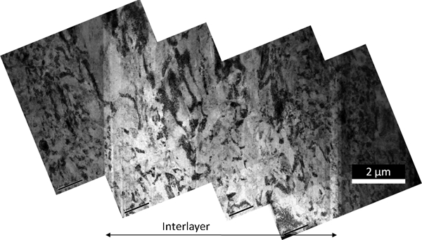
Stitched TEM image of weld interface including interlayer
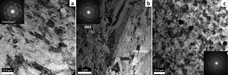
Images (TEM) and respective SAED patterns
Owing to the small number of TEM studies in MPW and EXW, very limited information is available on the character of the interlayer in the literature. The available findings22 suggest that a submicrometre reaction layer forms in dissimilar EXW bonds. However, given the welding conditions and materials, the connection to the present work is limited.
The boundaries of the interlayer and its different colour indicate a critical point, such as a phase change. Since the interface is the area of the highest strain, it should contain DRX grains. However, the interlayer appears to have enlarged grains with poorly defined grain boundaries, which could be the result of excess heat input. The lack of a solidification structure and the sharp boundary mean that the interlayer was in a high temperature plasticised flow, possibly in the ‘mushy zone’ of the phase diagram. As shown in Fig. 14, this is the semisolid state, at approximately 575–625°C for AZ31. Figure 14 demonstrates the possible temperature gradient of the interface, which accounts for the structural difference between the interlayer and the nearby nanoscale DRX grains.
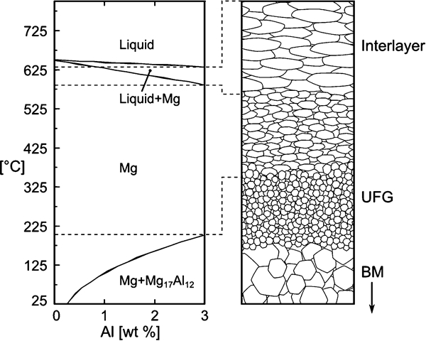
Schematic diagram of temperatures and states in bond zone including interlayer, ultrafine grains and base metal grains
With higher discharge energy, more kinetic energy would be generated in the sheets, and thus, more dissipation will occur at the interface, creating more heat. Higher temperatures will create a longer wavy interface and correspondingly longer interlayer. Welds made with geometry parameters β held constant will have an interlayer length that is proportional to the discharge energy.
Conclusions
In the present study, lap joints of AZ31 Mg alloy sheets were successfully produced using the MPW process. The bond displayed high shear strength approximately equivalent to the base metal shear strength. The resultant joint consisted of an unbonded centre zone and two twin bond zones. Strain localisation in the form of shear bands confirms that bonding did not occur in the unbonded centre zone due to the very low collision angle β. In this zone, because of a small β, jetting of oxides and contaminates did not occur, and no bonding took place. In the bond zones of the joint, oxides and contaminates were successfully removed. Two distinct fracture surfaces were found in the bond zone, one with regular shear platelet-like appearance and another very fine cup cone pattern in the latter part of the bond zone. Shearing deformation created a plastic flow of uncontaminated material that joined to form an interlayer at the weld interface. It is suggested that the interlayer is responsible for the high strength of the joint and its ductile fracture. Ultrafine equiaxed grains (∼300 nm diameter) and severely elongated grains were observed at a distance away from the weld interface, indicative of severe plastic deformation.
Footnotes
Acknowledgements
This research was financially supported by the Natural Sciences and Engineering Research Council (NSERC) of Canada in the Framework of the Magnesium Network (MagNET) Strategic Network programme. Material donations from South Korea's POSCO Company are greatly appreciated. The authors would like to thank L. Xiao for aid in TEM work.